


 Loading...
MIC IP starlight 7000i
MIC-7502-Z30B│MIC-7502-Z30W│MIC-7502-Z30G
en Installation Manual

MIC IP starlight 7000i |
Table of contents | en |
3 |
|
|
|
Table of contents
1 |
Safety |
4 |
1.1 |
About this Manual |
4 |
1.2 |
Legal Information |
4 |
1.3 |
Safety Precautions |
4 |
1.4 |
Important Safety Instructions |
5 |
1.5 |
Important Notices |
6 |
1.6 |
Customer Support and Service |
10 |
2 |
|
|
Unpacking |
11 |
|
2.1 |
Parts List - Camera |
11 |
2.2 |
Additional Tools |
11 |
3 |
Product Description |
12 |
4 |
Installation Overview |
13 |
5 |
Configuration Programming in the Shipping Box |
14 |
6 |
Configuration Programming on a Temporary Table-top Stand |
15 |
7 |
Mounting |
16 |
7.1 |
Mounting Location Options |
16 |
7.2 |
Mounting Orientation Options |
16 |
7.3 |
Mounting Bracket Options and Accessories |
19 |
7.4 |
Canting the Camera |
22 |
8 |
Connections |
27 |
8.1 |
About Camera Power and Control |
27 |
8.2 |
Power Source Options |
27 |
8.3 |
Ethernet Connections |
28 |
8.4 |
Camera Connections |
28 |
8.5 |
Connect the Camera to the Network |
29 |
9 |
|
|
Typical System Configurations |
30 |
|
9.1 |
Typical IP Configuration with High PoE midspan (no I/O connections) |
30 |
9.2 |
Typical Configuration with MIC-ALM-WAS-24 |
31 |
9.3 |
Typical IP Configuration with VJC-7000-90 |
32 |
10 |
|
|
Illumination/Wiper |
33 |
|
11 |
Maintenance |
35 |
12 |
Decommissioning |
36 |
12.1 |
Transfer |
36 |
12.2 |
Disposal |
36 |
13 |
Appendices |
37 |
13.1 |
Best Practices for Outdoor Installation |
37 |
13.2 |
Error Codes |
39 |
13.3 |
AUX Commands |
44 |
Bosch Security Systems |
Installation Manual |
2017.09 | 0.12 | F.01U.xxx.xxx |
4 |
en | Safety |
MIC IP starlight 7000i |
|
|
|
1 Safety
1.1About this Manual
This manual has been compiled with great care and the information it contains has been thoroughly verified. The text was complete and correct at the time of printing. Because of the ongoing development of products, the content of the manual may change without notice. Bosch Security Systems accepts no liability for damage resulting directly or indirectly from faults, incompleteness, or discrepancies between the manual and the product described.
1.2Legal Information
Copyright
This manual is the intellectual property of Bosch Security Systems, Inc. and is protected by copyright. All rights reserved.
Trademarks
All hardware and software product names used in this document are likely to be registered trademarks and must be treated accordingly.
1.3Safety Precautions
In this manual, the following symbols and notations are used to draw attention to special situations:
Danger!
High risk: This symbol indicates an imminently hazardous situation such as “Dangerous Voltage” inside the product. If not avoided, this will result in an electrical shock, serious bodily injury, or death.
Warning!
!Medium risk: Indicates a potentially hazardous situation. If not avoided, this may result in minor or moderate injury.
Caution!
!Low risk: Indicates a potentially hazardous situation. If not avoided, this may result in property damage or risk of damage to the unit.
Notice!
This symbol indicates information or a company policy that relates directly or indirectly to the safety of personnel or protection of property.
2017.09 | 0.12 | F.01U.xxx.xxx |
Installation Manual |
Bosch Security Systems |

MIC IP starlight 7000i |
Safety | en |
5 |
|
|
|
1.4Important Safety Instructions
Read, follow, and retain all of the following safety instructions. Heed all warnings on the unit
and in the operating instructions before operation.
Caution!
!TO REDUCE THE RISK OF ELECTRIC SHOCK, DISCONNECT THE POWER SOURCE WHILE INSTALLING THE DEVICE.
Caution!
Installation must be made by qualified personnel and conform to ANSI/NFPA 70 (the National
!Electrical Code® (NEC)), Canadian Electrical Code, Part I (also called CE Code or CSA C22.1), and all applicable local codes. Bosch Security Systems, Inc. accepts no liability for any
damages or losses caused by incorrect or improper installation.
Warning!
INSTALL EXTERNAL INTERCONNECTING CABLES IN ACCORDANCE TO NEC, ANSI/NFPA70
(FOR US APPLICATION) AND CANADIAN ELECTRICAL CODE, PART I, CSA C22.1 (FOR CAN
!COUNTRIES. BRANCH CIRCUIT PROTECTION INCORPORATING A 20 A, 2-POLE LISTED CIRCUIT BREAKER OR BRANCH RATED FUSES ARE REQUIRED AS PART OF THE BUILDING
INSTALLATION. A READILY ACCESSIBLE 2-POLE DISCONNECT DEVICE WITH A CONTACT SEPARATION OF AT LEAST 3 mm MUST BE INCORPORATED.APPLICATION) AND IN ACCORDANCE TO LOCAL COUNTRY CODES FOR ALL OTHER
Warning!
!ROUTING OF EXTERNAL WIRING MUST BE DONE THROUGH A PERMANENTLY EARTHED METAL CONDUIT.
Warning!
!THE CAMERA MUST BE MOUNTED DIRECTLY AND PERMANENTLY TO A NON-COMBUSTIBLE SURFACE.
–Do not place a canted (45°) camera upright; it can fall over easily. Place the canted camera on its side.
–Do not open the camera unit. Doing so will invalidate the warranty.
Use common-sense safety precautions, especially in situations where there could be risk of injury if any part of the assembly becomes detached and falls. Bosch recommends using the hinged DCA, which allows installers to “hang” the MIC camera temporarily on the DCA to make electrical connections, before bolting the camera to the DCA.
–Ensure that the unit case is properly earthed. If the product is at risk of being struck by lightning, ensure that earth bonding connections are made correctly to the mounting of the base of the unit.
–Do not point the camera at the sun. Bosch Security Systems will not be liable for any damage to cameras that have been pointed directly at the sun.
–Before transporting, supply power to the camera and rotate the ball so that the window points toward the base. This will help to protect the wiper and the window during transit.
Bosch Security Systems |
Installation Manual |
2017.09 | 0.12 | F.01U.xxx.xxx |
6 |
en | Safety |
MIC IP starlight 7000i |
|
|
|
|
|
|
Warning!
Do not manually back drive the camera
The motor/gear head combinations used in the MIC cameras were designed to provide smooth pan/tilt movement of the camera during powered operation. The gear heads were not
!Although it might be possible to do so on unpowered units, there is no guarantee that “backdriving” will be possible on every unit. Some units may even enter a “locked-up” mechanical state.
If the camera becomes “locked-up,” simply apply power to the camera. The pan/tilt functions of the camera should now operate properly.specifically designed to be manually “back-driven” under any circumstance.
Warning!
!Moving parts may result in risk of injury, therefore, the device should be mounted so that it is accessible only to the technician/installer.
Notice!
Always use a shielded twisted pair (STP) connection cable and a shielded RJ45 network cable connector where the camera is used outdoors or the network cable is routed outdoors. Always use shielded cables/connectors in demanding indoor electrical environments where the network cable is located in parallel with electrical mains supply cables, or where large inductive loads such as motors or contactors are near the camera or its cable.
Notice!
Bosch recommends the use of surge/lightning protection devices (sourced locally) to protect network and power cables and the camera installation site. Refer to NFPA 780, Class 1 & 2, UL96A, or the equivalent code appropriate for your country/region, and to local building codes. Refer also to the installation instructions of each device (surge protector where the cable enters the building, midspan, and camera).
1.5Important NoticesMoving parts!
For use in China: CHINA ROHS DISCLOSURE TABLE
Moving cameras
Hazardous substance table according to SJ/T 11364-2014
|
Pb |
Hg |
Cd |
Cr 6+ |
PBB |
PBDE |
|
(Pb) |
(Hg) |
(Cd) |
(Cr 6+) |
(PBB) |
(PBDE) |
|
|
|
|
|
|
|
Housing & enclosures |
X |
O |
O |
O |
O |
O |
PCBA with connectors |
X |
O |
X |
O |
O |
O |
Cable assemblies |
O |
O |
O |
O |
O |
O |
Image sensor assembly |
X |
O |
X |
O |
O |
O |
Lens assembly |
X |
O |
X |
O |
O |
O |
PT Motor control assembly |
X |
O |
X |
O |
O |
O |
Fan assembly |
X |
O |
X |
O |
O |
O |
2017.09 | 0.12 | F.01U.xxx.xxx |
Installation Manual |
Bosch Security Systems |
MIC IP starlight 7000i |
Safety | en |
7 |
|
|
|
Hazardous substance table according to SJ/T 11364-2014
This table was created according to the provisions of SJ/T 11364
O: The content of such hazardous substance in all homogeneous materials of such component is below the limit defined in GB/T 26572
X: The content of such hazardous substance in a certain homogeneous material is above the limit defined in GB/T 26572
The manufacturing datecodes of the products are explained in:
http://www.boschsecurity.com/datecodes/
Notice!
This device is intended for use in public areas only.
U.S. federal law strictly prohibits surreptitious recording of oral communications.
Accessories - Do not place this unit on an unstable stand, tripod, bracket, or mount. The unit may fall, causing serious injury and/or serious damage to the unit. Use only with mounting solutions specified by the manufacturer. When a cart is used, use caution and care when moving the cart/unit combination to avoid injury from tip-over. Quick stops, excessive force, or uneven surfaces may cause the cart/unit combination to overturn. Mount the unit per the installation instructions.
Adjustment of controls - Adjust only those controls specified in the operating instructions. Improper adjustment of other controls may cause damage to the unit.
All-pole power switch - Incorporate an all-pole power switch, with a contact separation of at least 3 mm, into the electrical installation of the building. If the camera requires service, use this all-pole switch as the main disconnect device for switching off the voltage to the unit.
Camera signal - Protect the cable with a primary protector if the camera signal is beyond 140 feet, in accordance with NEC800 (CEC Section 60).
Environmental statement - Bosch has a strong commitment towards the environment. This unit has been designed to respect the environment as much as possible.
Electrostatic-sensitive device - Use proper ESD safety precautions when handling the camera to avoid electrostatic discharge.
Fuse rating - For security protection of the device, the branch circuit protection must be secured with a maximum fuse rating of 16A. This must be in accordance with NEC800 (CEC Section 60).
Grounding:
-Connect outdoor equipment to the unit's inputs only after this unit has had its ground terminal connected properly to a ground source.
-Disconnect the unit's input connectors from outdoor equipment before disconnecting the grounding terminal.
-Follow proper safety precautions such as grounding for any outdoor device connected to this unit.
U.S.A. models only - Section 810 of the National Electrical Code, ANSI/NFPA No.70, provides information regarding proper grounding of the mount and supporting structure, size of grounding conductors, location of discharge unit, connection to grounding electrodes, and requirements for the grounding electrode.
Bosch Security Systems |
Installation Manual |
2017.09 | 0.12 | F.01U.xxx.xxx |
8 |
en | Safety |
MIC IP starlight 7000i |
|
|
|
Heat sources - Do not install unit near any heat sources such as radiators, heaters, or other equipment (including amplifiers) that produce heat.
Moving - Before moving the unit, disconnect both the 24 VAC connection and the Ethernet cable connection (if using PoE).
Outdoor signals - The installation for outdoor signals, especially regarding clearance from power and lightning conductors and transient protection, must be in accordance with NEC725 and NEC800 (CEC Rule 16-224 and CEC Section 60).
Refer to the ”Best Practices for Outdoor Installation, page 37” section of the manual for more information on outdoor installations.
Permanently connected equipment - Incorporate a readily accessible disconnect device in the building installation wiring.
Power lines - Do not locate the camera near overhead power lines, power circuits, or electrical lights, nor where it may contact such power lines, circuits, or lights.
Damage requiring service – Unplug the devices from the main AC power source and refer servicing to qualified service personnel whenever any damage to the device has occurred, such as:
-the power supply cable is damaged;
-an object has fallen on the device;
-the device has been dropped, or its enclosure has been damaged;
-the device does not operate normally when the user follows the operating instructions correctly.
Servicing - Do not attempt to service this device yourself. Refer all servicing to qualified service personnel.
This device has no user-serviceable parts.
Notice!
This is a class A product. In a domestic environment this product may cause radio interference, in which case the user may be required to take adequate measures.
Notice!
Ce produit est un appareil de Classe A. Son utilisation dans une zone résidentielle risque de provoquer des interférences. Le cas échéant, l’utilisateur devra prendre les mesures nécessaires pour y remédier.
FCC & ICES Information
(U.S.A. and Canadian Models Only)
This device complies with part 15 of the FCC Rules. Operation is subject to the following conditions:
–this device may not cause harmful interference, and
–this device must accept any interference received, including interference that may cause
undesired operation.
NOTE: This equipment has been tested and found to comply with the limits for a Class A digital device, pursuant to Part 15 of the FCC Rules and ICES-003 of Industry Canada. These limits are designed to provide reasonable protection against harmful interference when the equipment is operated in a commercial environment. This equipment generates, uses, and radiates radio frequency energy and, if not installed and used in accordance with the
2017.09 | 0.12 | F.01U.xxx.xxx |
Installation Manual |
Bosch Security Systems |

MIC IP starlight 7000i |
Safety | en |
9 |
|
|
|
instruction manual, may cause harmful interference to radio communications. Operation of this equipment in a residential area is likely to cause harmful interference, in which case the user will be required to correct the interference at his expense.
Intentional or unintentional modifications, not expressly approved by the party responsible for compliance, shall not be made. Any such modifications could void the user's authority to operate the equipment. If necessary, the user should consult the dealer or an experienced radio/television technician for corrective action.
The user may find the following booklet, prepared by the Federal Communications Commission, helpful: How to Identify and Resolve Radio-TV Interference Problems. This booklet is available from the U.S. Government Printing Office, Washington, DC 20402, Stock No. 004-000-00345-4.
Informations FCC et ICES
(modèles utilisés aux États-Unis et au Canada uniquement)
Ce produit est conforme aux normes FCC partie 15. la mise en service est soumises aux deux conditions suivantes :
–cet appareil ne peut pas provoquer d'interférence nuisible et
–cet appareil doit pouvoir tolérer toutes les interférences auxquelles il est soumit, y compris les interférences qui pourraient influer sur son bon fonctionnement.
AVERTISSEMENT: Suite à différents tests, cet appareil s’est révélé conforme aux exigences imposées aux appareils numériques de Classe A en vertu de la section 15 du règlement de la Commission fédérale des communications des États-Unis (FCC). Ces contraintes sont destinées à fournir une protection raisonnable contre les interférences nuisibles quand l'appareil est utilisé dans une installation commerciale. Cette appareil génère, utilise et émet de l'energie de fréquence radio, et peut, en cas d'installation ou d'utilisation non conforme aux instructions, générer des interférences nuisibles aux communications radio. L’utilisation de ce produit dans une zone résidentielle peut provoquer des interférences nuisibles. Le cas échéant, l’utilisateur devra remédier à ces interférences à ses propres frais.
Au besoin, l’utilisateur consultera son revendeur ou un technicien qualifié en radio/télévision, qui procédera à une opération corrective. La brochure suivante, publiée par la Commission fédérale des communications (FCC), peut s’avérer utile : How to Identify and Resolve Radio-TV Interference Problems (Comment identifier et résoudre les problèmes d’interférences de radio et de télévision). Cette brochure est disponible auprès du U.S. Government Printing Office, Washington, DC 20402, États-Unis, sous la référence n° 004-000-00345-4.
Bosch Security Systems |
Installation Manual |
2017.09 | 0.12 | F.01U.xxx.xxx |

10 en | Safety |
MIC IP starlight 7000i |
|
|
1.6Customer Support and Service
If this unit needs service, contact the nearest Bosch Security Systems Service Center for authorization to return and shipping instructions.
Service Centers
USA
Telephone: 800-366-2283 or 585-340-4162
Fax: 800-366-1329
Email: cctv.repair@us.bosch.com
Customer Service
Telephone: 888-289-0096
Fax: 585-223-9180
Email: security.sales@us.bosch.com
Technical Support
Telephone: 800-326-1450
Fax: 585-223-3508 or 717-735-6560
Email: technical.support@us.bosch.com
Repair Center
Telephone: 585-421-4220
Fax: 585-223-9180 or 717-735-6561
Email: security.repair@us.bosch.com
Canada
Telephone: 514-738-2434
Fax: 514-738-8480
Europe, Middle East & Africa Region
Please contact your local distributor or Bosch sales office. Use this link:
http://www.boschsecurity.com/startpage/html/europe.htm
Asia Pacific Region
Please contact your local distributor or Bosch sales office. Use this link:
http://www.boschsecurity.com/startpage/html/asia_pacific.htm
More Information
For more information please contact the nearest Bosch Security Systems location or visit www.boschsecurity.com
2017.09 | 0.12 | F.01U.xxx.xxx |
Installation Manual |
Bosch Security Systems |
MIC IP starlight 7000i |
Unpacking | en 11 |
|
|
2 Unpacking
–This equipment should be unpacked and handled with care. Check the exterior of the packaging for visible damage. If an item appears to have been damaged in shipment, notify the shipper immediately.
–Verify that all the parts listed in the Parts List below are included. If any items are missing, notify your Bosch Security Systems Sales or Customer Service Representative.
–Do not use this product if any component appears to be damaged. Please contact Bosch Security Systems in the event of damaged goods.
–The original packing carton is the safest container in which to transport the unit and must be used if returning the unit for service. Save it for possible future use.
Caution!
!Take extra care lifting or moving MIC cameras because of their weight.
The MIC packaging is designed:
–to allow installers to configure the camera inside the shipping box.
–to provide a temporary table-top or desk-top stand.
2.1Parts List - Camera
Quantity |
Component |
|
|
1 |
MIC IP starlight 7000i camera |
|
|
1 |
Safety and Unpacking Guide document |
|
|
1 |
Spanner wrench [to remove and to attach the yoke caps in order to cant the |
|
camera if desired, and to remove the access plug from the camera head when |
|
installing the optional illuminator accessory (sold separately) |
|
|
1 |
Quick Installation Guide |
|
|
1 |
base gasket |
|
|
1 |
RJ45 coupler (attached to the RJ-45 connector of the camera) |
|
|
4 |
MAC address labels |
|
|
1 |
Ground screw |
|
|
2.2Additional Tools
The following table lists additional tools (not supplied by Bosch) that may be required to install a MIC camera or its accessories:
1 Phillips-head screwdriver to secure the ground lug of the camera
1 Adjustable wrench or socket set to secure the base of the camera to mounting accessories
For canting cameras:
1 Torque wrench with a 5 mm Hex bit (or T30 Torx bit) to remove/install bolts in the yoke arms
Bosch Security Systems |
Installation Manual |
2017.09 | 0.12 | F.01U.xxx.xxx |

12 en | Product Description MIC IP starlight 7000i
3 Product Description
The MIC IP starlight 7000i camera is an advanced PTZ surveillance platform designed to provide early detection in mission-critical applications. With starlight imaging technology and excellent low-light sensitivity, the MIC IP starlight 7000i camera is the perfect solution for robust and high-quality imaging needs.
The camera also has a 30x optical zoom (12x digital) and flexible, field-selectable mounting orientations (upright, inverted, or canted) to achieve the perfect field of view.
A long-life silicone wiper blade mounted on a spring-loaded arm is standard on all MIC cameras.
The following table identifies the optional accessories for MIC cameras. Refer to the datasheets of each accessory for details. Some accessories may not be available in all regions.
Accessories |
Description |
|
Accessories |
Description |
|
|
|
|
|
MIC-DCA-H |
Hinged Deep Conduit Adapter in |
|
MIC-SCA |
Shallow Conduit Adapter in |
- MIC-DCA-HB |
Black |
|
- MIC-SCA-BD |
Black |
- MIC-DCA-HW |
White |
|
- MIC-SCA-WD |
White |
- MIC-DCA-HG |
Grey |
|
- MIC-SCA-MG |
Grey |
- MIC-DCA-HBA |
Black with M25 to ¾” adapter |
|
|
|
- MIC-DCA-HWA |
White with M25 to ¾” adapter |
|
|
|
- MIC-DCA-HGA |
Grey with M25 to ¾” adapter |
|
|
|
|
|
|
|
|
MIC-CMB |
Corner Mount Bracket in |
|
MIC-SPR |
Spreader Plate in |
- MIC-CMB-BD |
Black |
|
- MIC-SPR-BD |
Black |
- MIC-CMB-WD |
White |
|
- MIC-SPR-WD |
White |
- MIC-CMB-MG |
Grey |
|
- MIC-SPR-MG |
Grey |
|
|
|
|
|
MIC-WMB |
Wall Mount Bracket in |
|
MIC-PMB |
Pole Mount Bracket (stainless steel |
- MIC-WMB-BD |
Black |
|
|
only) |
- MIC-WMB-WD |
White |
|
|
|
- MIC-WMB-MG |
Grey |
|
|
|
|
|
|
|
|
NPD-9501A |
95 W midspan |
|
MIC-WKT-IR |
Washer Kit |
|
|
|
|
|
VG4-A-PSU1 |
24 VAC (96 VA) power supply |
|
MIC-ALM-WAS-24 |
Alarm and washer interface accessory |
VG4-A-PSU2 |
|
|
|
unit |
|
|
|
|
|
|
|
|
|
|
NPD-6001A |
60 W midspan [Not for use with |
|
VJC-7000-90 |
VIDEOJET connect (Full-featured |
|
the illuminator accessory.] |
|
|
network interface unit/power supply) |
|
|
|
|
|
MICIP67-5PK |
MIC7000 IP67 Connector Kit |
|
MIC-67SUNSHLD |
Sunshield (white only) |
|
|
|
|
|
MIC-ILx-300 |
User-installable illuminator |
|
MVS-FCOM-PRCL |
Serial protocol license for IP cameras |
|
accessory specifically for MIC IP |
|
|
|
|
starlight 7000i cameras, in |
|
|
|
- MIC-ILB-300 |
Black |
|
|
|
- MIC-ILW-300 |
White |
|
|
|
- MIC-ILG-300 |
Grey |
|
|
|
|
|
|
|
|
2017.09 | 0.12 | F.01U.xxx.xxx |
Installation Manual |
Bosch Security Systems |
MIC IP starlight 7000i Installation Overview | en 13
4 Installation Overview
Caution!
Installation must be made by qualified personnel and conform to ANSI/NFPA 70 (the National
!Electrical Code® (NEC)), Canadian Electrical Code, Part I (also called CE Code or CSA C22.1), and all applicable local codes. Bosch Security Systems, Inc. accepts no liability for any
damages or losses caused by incorrect or improper installation.
Caution!
ELECTRIC SHOCK HAZARD
!To reduce the risk of electric shock, disconnect power to the camera and/or to the power supply unit before moving the camera, before installing any accessories, and before mounting
the camera.
Notice!
To maintain the NEMA 6P rating when the camera is mounted to a MIC-DCA, installers must ensure that the user-supplied cable glands or conduit connections have NEMA 6P ratings.
Notice!
Outdoor installation
For details about the proper configuration for installing your camera outdoors with surge and lightning protection, refer to Best Practices for Outdoor Installation, page 37.
Bosch Security Systems |
Installation Manual |
2017.09 | 0.12 | F.01U.xxx.xxx |
14 en | Configuration Programming in the Shipping Box MIC IP starlight 7000i
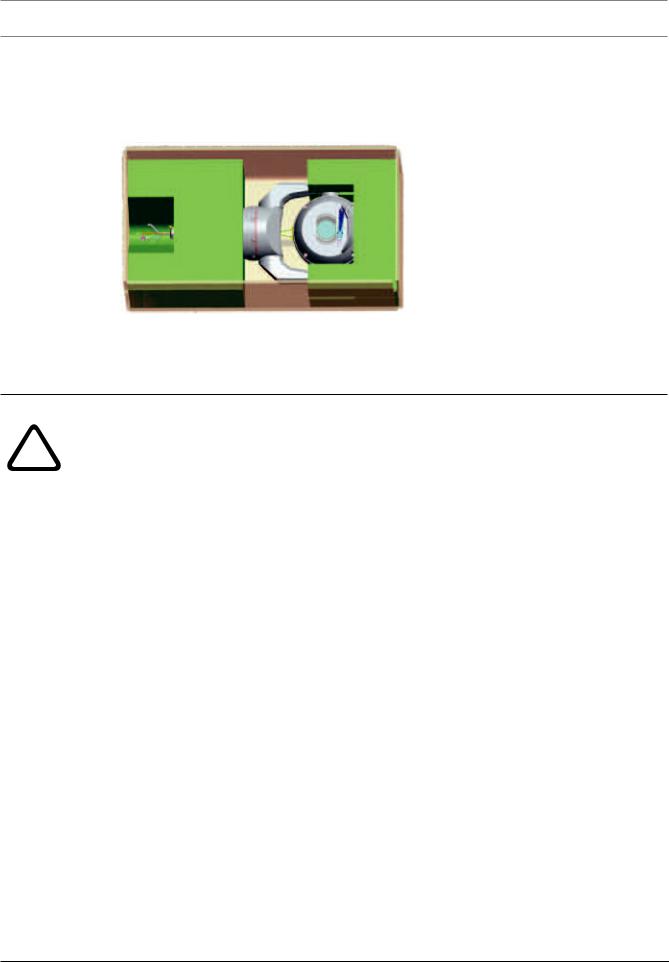
5 Configuration Programming in the Shipping Box
The camera packaging allows installers to connect the camera to the network and configure
the camera still in the box.
1. Remove the accessories box from the top, middle section of the box.
2. Supply power to the camera and Connect the Camera to the Network, page 29. Note that the wiper moves one to three times across the camera window, and then returns to parked position.
3. Configure the camera. Refer to Configuration for details.
|
Caution! |
|
|
Risk of damage to camera |
|
! |
Do not change the camera orientation to “Inverted” while the camera is still in the box. The |
|
camera head must be free to rotate. If you must change the camera’s orientation to |
||
|
||
|
“Inverted,” remove the camera from the box and configure it by following the steps in |
|
|
Configuration Programming on a Temporary Table-top Stand, page 15. |
|
|
|
|
|
4. Disconnect the wires/cables from the connectors in the base of the camera. |
2017.09 | 0.12 | F.01U.xxx.xxx |
Installation Manual |
Bosch Security Systems |
MIC IP starlight 7000i Configuration Programming on a Temporary Table-top Stand | en 15
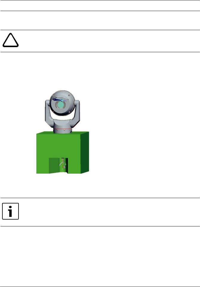
6 |
Configuration Programming on a Temporary Table-top |
|
Stand |
Caution!
!Take extra care lifting or moving MIC cameras because of their weight.
The camera (still in the foam) can stand temporarily on a flat, horizontal surface such as a desk or a table during initial network connection and configuration.
1.Remove the accessories box from the top, middle section of the box.
2.Remove the foam covering the head of the camera.
3.Remove the camera, still in the foam, from the box. Place the camera upright on a flat, horizontal surface.
4.Supply power to the camera and Connect the Camera to the Network, page 29. Note that the wiper moves one to three times across the camera window, and then returns to parked position.
5.Configure the camera. Refer to Configuration for details.
Notice!
If you change the camera orientation to “Inverted” (from the page Configuration of the web browser: Camera > Installer Menu > Orientation), then the camera head will rotate automatically into inverted position (180°). Note that the visor will now be near the body of the camera.
6. Disconnect the wires/cables from the connectors in the base of the camera.
Bosch Security Systems |
Installation Manual |
2017.09 | 0.12 | F.01U.xxx.xxx |
Loading...