


MIC IP PSU
Bosch MIC IP PSU, MIC-IP-PS-115, MIC-IP-PS-230, MIC-IP-PS-24, MIC-IPIR-PS-115 User Manual
...
MIC Series IP Power Supply
MIC IP PSU
en User Manual


MIC Series IP Power Supply Table of Contents | en 3
Bosch Security Systems, Inc. User Manual F.01U.265.804 | 1.6 | 2012.08
Table of Contents
1Safety 6
1.1 About this Manual 6
1.2 Conventions in this Manual 6
1.3 Legal Information 6
1.4 Important safety instructions/notices 7
2 Product Description 10
2.1 Overview of Functions 10
2.2 Summary of Functions 11
3 Installation 12
3.1 Parts List 12
3.1.1 User-Supplied Parts 12
3.1.2 User-Supplied Tools 12
3.2 Dimensions and Layout of MIC IP Power Supplies 13
3.3 MIC Power Supply Units (PSUs) for Non-IR MIC Cameras 14
3.4 MIC Power Supply Units (PSUs) for IR MIC Cameras 15
3.5 Earth Link on the PCB 15
3.6 Fuse Ratings 16
3.7 Installation Instructions 17
3.8 Commissioning the Camera with Heater Option Fitted 25
3.9 Simultaneous IP and Analog Video/Control ("Hybrid" Operation) 26
3.10 Assign an IP Address 26
3.11 Hardware connections between video servers 27
4 Configuration using a Web browser 28
4.1 Connecting 28
4.1.1 System Requirements 28
4.1.2 Additional Operational Requirements 28
4.1.3 Installing MPEG ActiveX 28
4.1.4 Establishing the Connection 28
4.2 Configuration menu 30
4.3 Basic Mode: Device Access 31
4.4 Basic Mode: Date/Time 32
4.5 Basic Mode: Network 33
4.6 Basic Mode: Encoder 34
4.7 Basic Mode: System Overview 35
4.8 Advanced Mode: General 36
4.9 Identification 36
4.10 Password 37
4.11 Date/Time 38
4.12 Display Stamping 39
4.13 Advanced Mode: Web Interface 40
4.14 Appearance 40
4.15 LIVEPAGE Functions 41
4.16 Logging 42

4 en | Table of Contents MIC Series IP Power Supply
F.01U.265.804 | 1.6 | 2012.08 User Manual Bosch Security Systems, Inc.
4.17 Video Input 43
4.18 Advanced Mode: Encoder 43
4.19 Picture Settings 43
4.20 Encoder Profile 44
4.21 Encoder Streams 47
4.22 Pixel Counter 48
4.23 Advanced Mode: Camera 48
4.24 Camera Options 48
4.25 Lens 50
4.26 PTZ 52
4.27 Display 52
4.28 Alarm 54
4.28.1 Input Options 54
4.28.2 Output Options 54
4.28.3 Alarm Rules 55
4.28.4 Alarm States 56
4.29 Miscellaneous 56
4.30 Logs 57
4.31 Advanced Mode: Recording 57
4.32 Storage Management 57
4.33 Recording Profiles 60
4.34 Retention Time 62
4.35 Recording Scheduler 63
4.36 Recording Status 64
4.37 Advanced Mode: Alarm 65
4.38 Alarm Connections 65
4.39 VCA 67
4.40 Alarm E-Mail 71
4.41 Alarm Task Editor 72
4.42 Advanced Mode: Network 73
4.43 Network Access 73
4.44 Advanced 75
4.45 Multicast 77
4.46 FTP Posting 79
4.47 IPv4 Filter 80
4.48 Encryption 80
4.49 Advanced Mode: Service 81
4.50 Maintenance 81
4.51 Licenses 83
4.52 System Overview 83
4.53 Function test 84
5Operation 85
5.1 Function test 85
5.2 The LIVEPAGE 85
5.3 Saving snapshots 87
5.4 Recording video sequences 87
5.5 Running recording program 87
5.6 Processor load 87

MIC Series IP Power Supply Table of Contents | en 5
Bosch Security Systems, Inc. User Manual F.01U.265.804 | 1.6 | 2012.08
5.7 Network connection 88
5.8 The RECORDINGS page 88
5.9 Operation using software decoders 90
6 Maintenance and upgrades 91
6.1 Testing the network connection 91
6.2 Unit reset 91
6.3 Troubleshooting 91
6.4 General malfunctions 92
6.5 Fiber Optic Module 93
6.6 Malfunctions with iSCSI connections 94
6.7 LEDs 94
6.8 Processor load 94
6.9 Network connection 94
6.10 Terminal block 95
6.11 Communication with terminal program 95
6.12 Transfer and disposal 97
6.13 Repairs 97
6.14 Copyrights 97
6 en | Safety MIC Series IP Power Supply
F.01U.265.804 | 1.6 | 2012.08 User Manual Bosch Security Systems, Inc.
1Safety
1.1 About this Manual
This manual has been compiled with great care and the information it contains has been
thoroughly verified. The text was complete and correct at the time of printing. Because of the
ongoing development of products, the content of the manual may change without notice.
Bosch Security Systems accepts no liability for damage resulting directly or indirectly from
faults, incompleteness, or discrepancies between the manual and the product described.
1.2 Conventions in this Manual
The following symbols and notations are used to draw attention to special situations:
1.3 Legal Information
Copyright - This manual is the intellectual property of Bosch Security Systems, Inc. and is
protected by copyright. All rights reserved.
Trademarks - All hardware and software product names used in this document are likely to be
registered trademarks and must be treated accordingly.
Notice of Regulatory Compliance
This product complies with the following EC directives:
– EMC Directive (89/336/EC as amended)
– LV Directive (73/23/EC)
– RoHS (Restriction of Hazardous Substances) 2002/95/ECEMC, CISPRA-B and CTIC
DANGER!
This symbol indicates an imminently hazardous situation such as “Dangerous Voltage” inside
the product. If not avoided, this will result in an electrical shock, serious bodily injury, or
death.
WARNING!
Indicates a potentially hazardous situation. If not avoided, this could result in serious bodily
injury or death.
CAUTION!
Medium Risk
Indicates a potentially hazardous situation. If not avoided, this may result in minor or
moderate injury. Alerts the user to important instructions accompanying the unit.
CAUTION!
Indicates a potentially hazardous situation. If not avoided, this may result in property damage
or risk of damage to the unit.
NOTICE!
This symbol indicates information or a company policy that relates directly or indirectly to the
safety of personnel or protection of property.

MIC Series IP Power Supply Safety | en 7
Bosch Security Systems, Inc. User Manual F.01U.265.804 | 1.6 | 2012.08
1.4 Important safety instructions/notices
Read, follow, and retain for future reference all of the following safety instructions. Heed all
warnings on the unit and in the operating instructions before operating the unit.
Installation - Do not install the unit:
– Near any heat sources such as radiators, heaters, stoves, or other equipment (including
amplifiers) that produce heat
– Near overhead power lines or power circuits, or where it may contact such power lines or
circuits
– In a built-in installation or rack without proper ventilation or adhering to the
manufacturer's instructions.
The equipment must not exceed its maximum operating temperature requirements.
Mount the unit properly in a rack to prevent a hazardous condition due to uneven
mechanical loading.
Power - Units have power supplied to the unit whenever the power cord is inserted into the
power source. The power cord is the main power disconnect device for switching off the
voltage to the unit. Disconnect the power before moving the unit or when leaving the unit
unattended and unused for long periods.
Protect the power supply cord and plug from foot traffic, from being pinched by items placed
on or against them at electrical outlets and at its exit from the unit. For units operating at
230 VAC, 50 Hz, the power cord must comply with the latest versions of IEC 60227. For units
operating at 120 VAC, 60 Hz, the power cord must comply with the latest versions of UL 62
and CSA 22.2 No.49.
Servicing - Do not attempt to service this unit yourself. Opening or removing covers may
expose you to dangerous voltage or other hazards. Refer all servicing to qualified service
personnel. If any of the following conditions occur, unplug the unit from the main AC power
source and refer servicing to qualified service personnel:
– the power supply cord or plug is damaged;
– exposure to moisture, water, and/or inclement weather (rain, snow, etc.);
– liquid has been spilled in or on the equipment;
– an object has been pushed or has fallen into the unit;
– the unit has been dropped or the unit cabinet is damaged;
– the unit exhibits a distinct change in performance;
– the unit does not operate normally when the user correctly follows the operating
instructions.
Ensure that service personnel use replacement parts specified by the manufacturer, or that
have the same characteristics as the original parts. Unauthorized substitutions may cause fire,
electrical shock, or other hazards. Service personnel should perform safety checks after
completion of service or repairs to the unit to ensure proper operating condition.
Modifications - Any change or modification of the equipment, not expressly approved by
Bosch, could void the warranty or, in the case of an authorization agreement, authority to
operate the equipment.
Electrostatic-sensitive device - Use proper CMOS/MOS-FET handling precautions to avoid
electrostatic discharge. Wear required grounded wrist straps and observe proper ESD safety
precautions when handling electrostatic-sensitive printed circuit boards.
Fuse rating - For security protection of the device, the branch circuit protection is required.
This must be in accordance with NEC800 (CEC Section 60) or other local codes.
Coax grounding:
– Ground the cable system if connecting an outside cable system to the unit.
8 en | Safety MIC Series IP Power Supply
F.01U.265.804 | 1.6 | 2012.08 User Manual Bosch Security Systems, Inc.
– Connect outdoor equipment to the unit's inputs only after connecting the grounding plug
to a grounded outlet, or its ground terminal is properly connected to a ground source.
– Disconnect the unit's input connectors from outdoor equipment before disconnecting
the grounding plug or grounding terminal.
– Follow proper safety precautions such as grounding for any outdoor device connected to
this unit.
U.S.A. models only - Section 810 of the National Electrical Code, ANSI/NFPA No.70, provides
information regarding proper grounding of the mount and supporting structure, grounding of
the coax to a discharge unit, size of grounding conductors, location of discharge unit,
connection to grounding electrodes, and requirements for the grounding electrode.
Outdoor signals - The installation for outdoor signals, especially regarding clearance from
power and lightning conductors and transient protection, must be in accordance with NEC725
and NEC800 (CEC Rule 16-224 and CEC Section 60).
Power resupply - If the unit is forced to power down due to exceeding the specified operating
temperatures, disconnect the power cord, wait for at least 30 seconds, and then reconnect
the power cord.
FCC & ICES Information
(U.S.A. and Canadian Models Only)
This equipment has been tested and found to comply with the limits for a Class B digital
device, pursuant to part 15 of the FCC Rules. These limits are designed to provide reasonable
protection against harmful interference in a residential installation. This equipment
generates, uses, and can radiate radio frequency energy and, if not installed and used in
accordance with the instructions, may cause harmful interference to radio communications.
However, there is no guarantee that interference will not occur in a particular installation. If
this equipment does cause harmful interference to radio or television reception, which can be
determined by turning the equipment off and on, the user is encouraged to try to correct the
interference by one or more of the following measures:
– reorient or relocate the receiving antenna;
– increase the separation between the equipment and receiver;
– connect the equipment into an outlet on a circuit different from that to which the
receiver is connected;
– consult the dealer or an experienced radio/TV technician for help.
Intentional or unintentional modifications, not expressly approved by the party responsible
for compliance, shall not be made. Any such modifications could void the user's authority to
operate the equipment. If necessary, the user should consult the dealer or an experienced
radio/television technician for corrective action.
The user may find the following booklet, prepared by the Federal Communications
Commission, helpful: How to Identify and Resolve Radio-TV Interference Problems. This booklet
is available from the U.S. Government Printing Office, Washington, DC 20402, Stock No. 004000-00345-4.
CAUTION!
Connecting System ground to Safety ground may result in ground loops that can disrupt the
CCTV system.
NOTICE!
This is a class B product. In a domestic environment this product may cause radio
interference, in which case the user may be required to take adequate measures.

MIC Series IP Power Supply Safety | en 9
Bosch Security Systems, Inc. User Manual F.01U.265.804 | 1.6 | 2012.08
INFORMATIONS FCC ET ICES
(modèles utilisés aux États-Unis et au Canada uniquement)
Suite à différents tests, cet appareil s'est révélé conforme aux exigences imposées aux
appareils numériques de classe B, en vertu de la section 15 du règlement de la Commission
fédérale des communications des États-Unis (FCC), et en vertu de la norme ICES-003 d'Industrie
Canada. Ces exigences visent à fournir une protection raisonnable contre les interférences
nuisibles lorsque l'appareil est utilisé dans le cadre d'une installation résidentielle. Cet
appareil génère, utilise et émet de l'énergie de radiofréquences et peut, en cas d'installation
ou d'utilisation non conforme aux instructions, engendrer des interférences nuisibles au
niveau des radiocommunications. Toutefois, rien ne garantit l'absence d'interférences dans
une installation particulière. Il est possible de déterminer la production d'interférences en
mettant l'appareil successivement hors et sous tension, tout en contrôlant la réception radio
ou télévision. L'utilisateur peut parvenir à éliminer les interférences éventuelles en prenant
une ou plusieurs des mesures suivantes:
– Modifier l'orientation ou l'emplacement de l'antenne réceptrice;
– Éloigner l'appareil du récepteur;
– Brancher l'appareil sur une prise située sur un circuit différent de celui du récepteur;
– Consulter le revendeur ou un technicien qualifié en radio/télévision pour obtenir de
l'aide.
Toute modification apportée au produit, non expressément approuvée par la partie
responsable de l'appareil, est strictement interdite. Une telle modification est susceptible
d'entraîner la révocation du droit d'utilisation de l'appareil.
La brochure suivante, publiée par la Commission fédérale des communications (FCC), peut
s'avérer utile : How to Identify and Resolve Radio-TV Interference Problems (Comment identifier
et résoudre les problèmes d’interférences de radio et de télévision). Cette brochure est
disponible auprès du U.S. Government Printing Office, Washington, DC 20402, États-Unis,
sous la référence n° 004-000-00345-4.
Dislaimer
Underwriter Laboratories Inc. (“UL”) has not tested the performance or reliability of the
security or signaling aspects of this product. UL has only tested fire, shock and/or casualty
hazards as outlined in UL's Standard(s) for Safety for Closed Circuit Television Equipment, UL
2044 and in Standard(s) for Safety for Information Technology Equipment, UL 60950-1. UL
Certification does not cover the performance or reliability of the security or signaling aspects
of this product.
UL MAKES NO REPRESENTATIONS, WARRANTIES, OR CERTIFICATIONS WHATSOEVER
REGARDING THE PERFORMANCE OR RELIABILITY OF ANY SECURITY OR SIGNALING RELATED
FUNCTIONS OF THIS PRODUCT.

10 en | Product Description MIC Series IP Power Supply
F.01U.265.804 | 1.6 | 2012.08 User Manual Bosch Security Systems, Inc.
2 Product Description
2.1 Overview of Functions
Network video server
The encoder is a compact network video server for a connected video source. It is primarily
designed for encoding video, audio, and control data for transfer over an IP network. With its
encoding in the H.264 format, the encoder is ideally suited for making existing analog CCTV
cameras IP-compatible and for remote access to digital VCRs and multiplexers. The use of
existing networks means that integration with CCTV systems or local networks can be
achieved quickly and easily. Two units, for example an encoder as a sender and a VIP XD as a
receiver, can create a standalone system for data transfer without a PC. Video images from a
single sender can be received simultaneously on multiple receivers. Audio signals can also be
transmitted from and to compatible units.
Receiver
Compatible H.264 enabled hardware decoders (for example the VIP XD) can be used as
receivers. Computers with decoding software such as VIDOS or computers with the Microsoft
Internet Explorer Web browser can also be used as receivers.
Video encoding
The encoder uses the H.264 video compression standard. Thanks to efficient encoding, the
data rate remains low even with high image quality and can also be adapted to local
conditions within wide limits.
Audio encoding
The encoder uses the G.711 and L16 audio compression standards. G.711 is the default
setting both for live transmission and recording. When configuring with a Web browser, you
can select L16 for recording. Using video management systems, L16 is also available for live
audio.
Dual Streaming
Dual Streaming allows the incoming data stream to be encoded simultaneously according to
two different, individually customized profiles. This feature creates two data streams that can
serve different purposes, for example one for recording and one optimized for live
transmission over the LAN.
Multicast
In suitably configured networks, the multicast function enables simultaneous real-time video
transmission to multiple receivers. The UDP and IGMP V2 protocols must be implemented on
the network for this function.
Encryption
The encoder offers a variety of options for protection against unauthorized reading. Web
browser connections can be protected using HTTPS. You can protect the control channels via
the SSL encryption protocol. With an additional license, the user data itself can be encrypted.
Remote control
For remote control of external units such as pan or tilt heads for cameras or motorized zoom
lenses, control data is transmitted via the encoder's bidirectional serial interface. This
interface can also be used to transmit transparent data.

MIC Series IP Power Supply Product Description | en 11
Bosch Security Systems, Inc. User Manual F.01U.265.804 | 1.6 | 2012.08
Video content analysis and tamper detection
The encoder offers a wide range of configuration options for alarm signaling in the event of
tampering with the connected camera. An algorithm for detecting movement in the video
image is also part of the scope of delivery. The standard version optionally can be extended to
include special video analysis algorithms.
Snapshots
Individual video frames (snapshots) from the encoder can be called up as JPEG images,
stored on the computer's hard drive or displayed in a separate browser window.
Recordings
Various local memory options enable the encoder to be used as a digital VCR. A connection to
an appropriately configured iSCSI system enables long-term recordings with high image
quality over the network.
Backup
A function for storing the video images displayed on the hard drive of your computer is
available on the LIVEPAGE as well as on the RECORDINGS page. Video sequences can be
stored by means of a mouse click and can be redisplayed using the Player program supplied
as part of the scope of delivery.
2.2 Summary of Functions
The encoder provides the following main functions:
– Video and data transmission over IP data networks
– Dual Streaming function for the encoder for simultaneous encoding with two individually
definable profiles
– Multicast function for simultaneous image transmission to multiple receivers
– One analog BNC composite video input (PAL/NTSC, 75 ohm)
– Video encoding to international standard H.264
– Integrated Ethernet port (10/100 Base-T)
– SD slot that supports local storage on SD cards (user-supplied) [ideal for shorter storage
times and temporary recordings, for example alarm recordings or local buffering in the
event of network interruptions]
– Transparent, bidirectional data channel via RS-232/RS-422/RS-485 serial interface
– Configuration and remote control of all internal functions via TCP/IP, also secured via
HTTPS
– Password protection to prevent unauthorized connection or configuration changes
– Extensive, flexible storage options
– Support for two alarm inputs and two relay outputs
– Built-in video sensor for motion and tamper alarms
– Event-controlled automatic connection
– Convenient maintenance via uploads
– Flexible encryption of control and data channels
– Authentication according to international standard 802.1x
– Bidirectional audio (mono) for line connections; transmitted in sync with the video signal
– Audio encoding to international standards G.711 or L16
12 en | Installation MIC Series IP Power Supply
F.01U.265.804 | 1.6 | 2012.08 User Manual Bosch Security Systems, Inc.
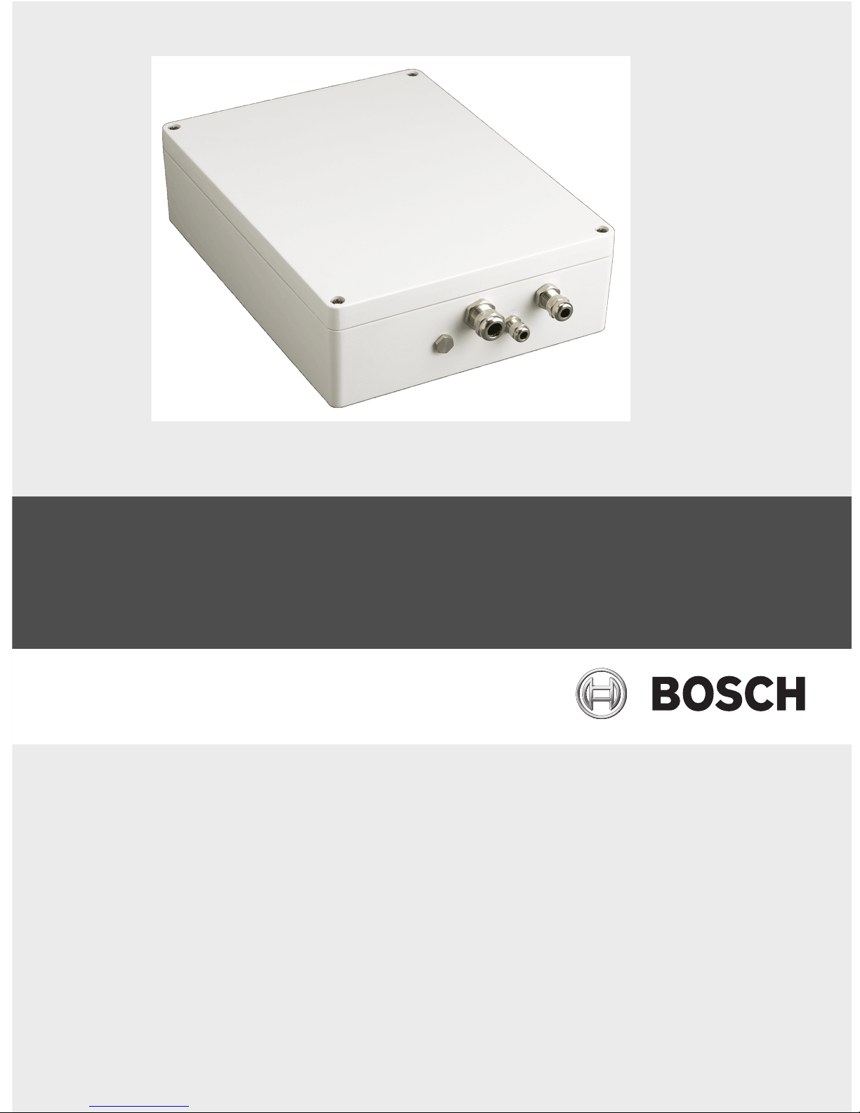
3 Installation
Each MIC power supply unit (PSU) provides all of the connections needed for power, video,
and telemetry for a single MIC camera. Each MIC PSU has CE and FCC approval and has an
aluminum enclosure that is weather-resistant (rated IP67). Features include:
– A built-in encoder for video and data transmission over an IP (standard 10/100 Base-T)
network
– A provision for driving various optional interface cards mounted internally to the MIC
power supply enclosure (for example, an 8-input alarm card (MIC-ALM))
– A provision for a signal interface card (MIC-BP4) to connect telemetry to Bosch Biphase
equipment
– Screw termination of all cables (composite, telemetry, and ancillary) into and out of the
enclosure
– Earth isolation and termination within the unit to control video earthing correctly and
thus prevent earth loops
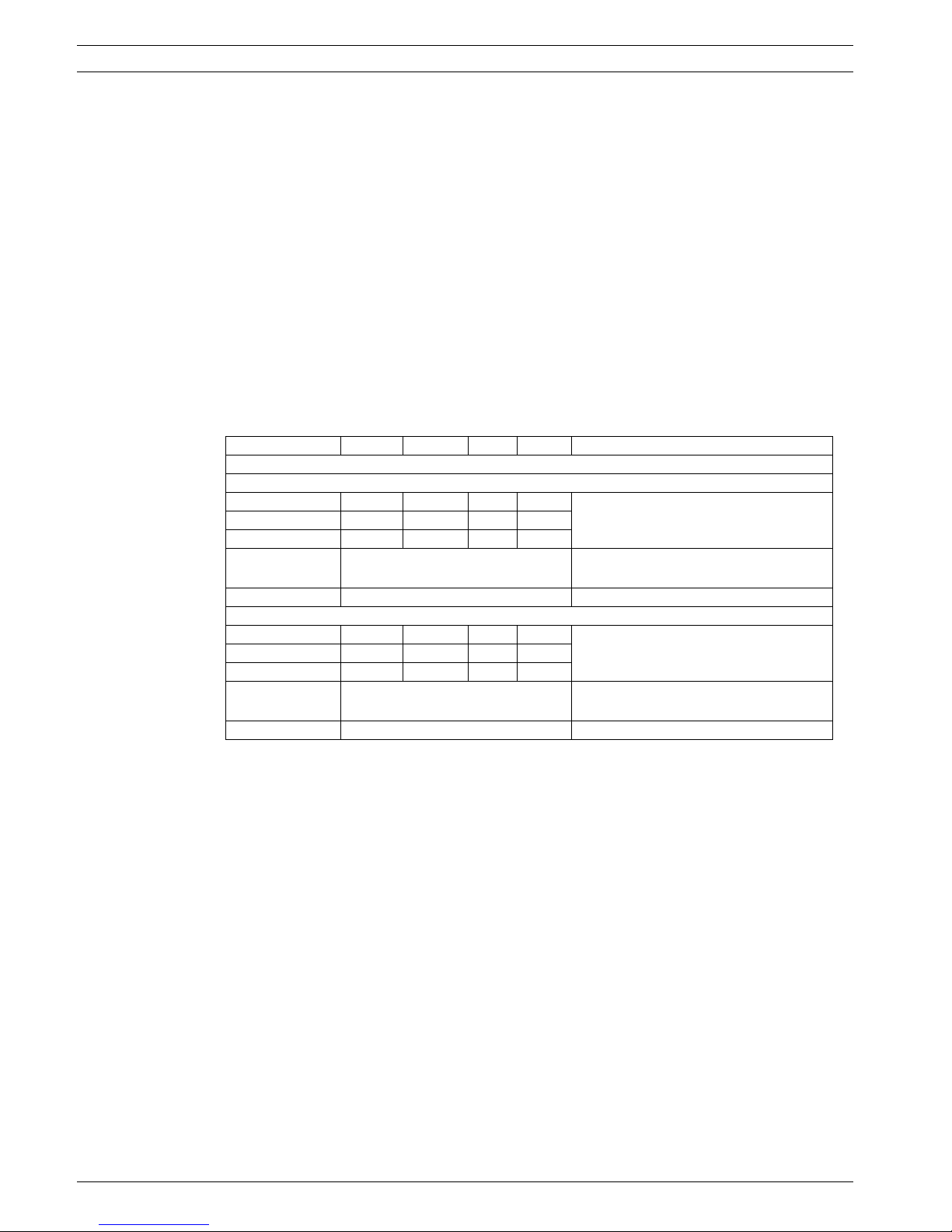
The table below summarizes the MIC power supplies and their specifications:
3.1 Parts List
Each MIC IP PSU ships with the following parts:
– Two (2) M12 cable glands for telemetry and ancillary equipment
– One (1) M16 gland for connection of RJ45 or Fiber cable
– One (1) 1/2 in. NPT cable gland for connection of the shielded composite cable to the
MIC camera
– One (1) 1/2 in. NPT cable gland for the power cable connection
– One (1) 1/2 in. NPT and one (1) M12 blanking plug
3.1.1 User-Supplied Parts
Installers must provide the following parts to complete installation of a MIC PSU:
– Power cable in the appropriate length
– Four (4) M6 stainless steel screws and washers
– Metal conduit suitable for containing power cables external to the PSU enclosure
– Ethernet cable (terminated as needed)
3.1.2 User-Supplied Tools
– Ring crimp tool (Davico type DHCR15 or equivalent)
– Phillips-head screwdriver
MIC PSU Voltage Hz Power Output Applicable MIC Cameras
IP Power Supply Units (Non-IR)
MIC-IP-PS-115 115 VAC 50/60 Hz 40 VA 18 VAC
MIC550, MIC612
MIC-IP-PS-230 230 VAC 50/60 Hz 40 VA 18 VAC
MIC-IP-PS-24 24 VAC 50/60 Hz 40 VA 18 VAC
Dimensions
(H x W x D)
330 x 250 x 90.75 mm
13 x 9.8 x 3.6 in.)
Weight 7.21 kg (15.9 lb)
IP IR Power Supply Units
MIC-IPIR-PS-115 115 VAC 50/60 Hz 60 VA 18 VAC
MIC550IR
MIC-IPIR-PS-230 230 VAC 50/60 Hz 60 VA 18 VAC
MIC-IPIR-PS-24 24 VAC 50/60 Hz 60 VA 18 VAC
Dimensions
(H x W x D)
330 x 250 x 90.75 mm
(13 x 9.8 x 3.6 in.)
Weight 7.3 kg (16.09 lb)
MIC Series IP Power Supply Installation | en 13
Bosch Security Systems, Inc. User Manual F.01U.265.804 | 1.6 | 2012.08
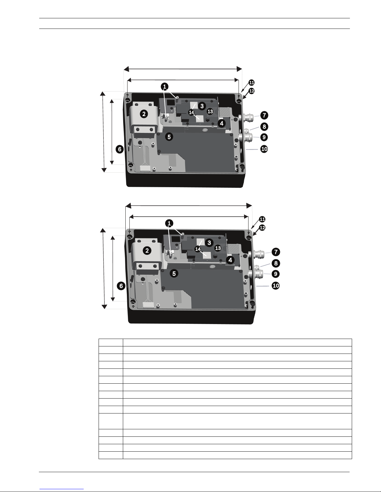
3.2 Dimensions and Layout of MIC IP Power Supplies
The figures below display the dimensions and the layout of the enclosures of the MIC IP PSUs.
Figure 3.1 Layout of MIC IP PSU (Model numbers: MIC-IP-PS-115, MIC-IP-PS-230, MIC-IP-PS-24)
Figure 3.2 Layout of MIC IP IR PSU (Model numbers: MIC-IPIR-PS-115, MIC-IPIR-PS-230, MIC-IPIR-PS-24)
Number Description
1 Two (2) metal stand-offs for fiber optic module (module sold separately)
2 Transformer
3Encoder
4 Power board for encoder
5 Main PCB (Different configuration for IR and non-IR models)
6 Blanking plug over hole in enclosure for power cable
7 Cable gland for RJ45 / Fiber cable
8 Cable gland for optional washer drive
9 Cable gland for composite cable (analog connection)
10 For non-thermal cameras: Blanking plug over hole for optional cable gland for alarms
For thermal cameras: Blanking plug over hole for output for optional switch video
11 Hole for lid screw
12 Hole for mounting screw
13 Slot for SD card (card is user-supplied)
14 Thermal pads between encoder and inside of lid of enclosure
(13 in.)
330 mm
(7.87 in.)
200 mm
(9.84 in.)
250 mm
(12.2 in.)
310 mm
(13 in.)
330 mm
(7.87 in.)
200 mm
(9.84 in.)
250 mm
(12.2 in.)
310 mm
14 en | Installation MIC Series IP Power Supply
F.01U.265.804 | 1.6 | 2012.08 User Manual Bosch Security Systems, Inc.
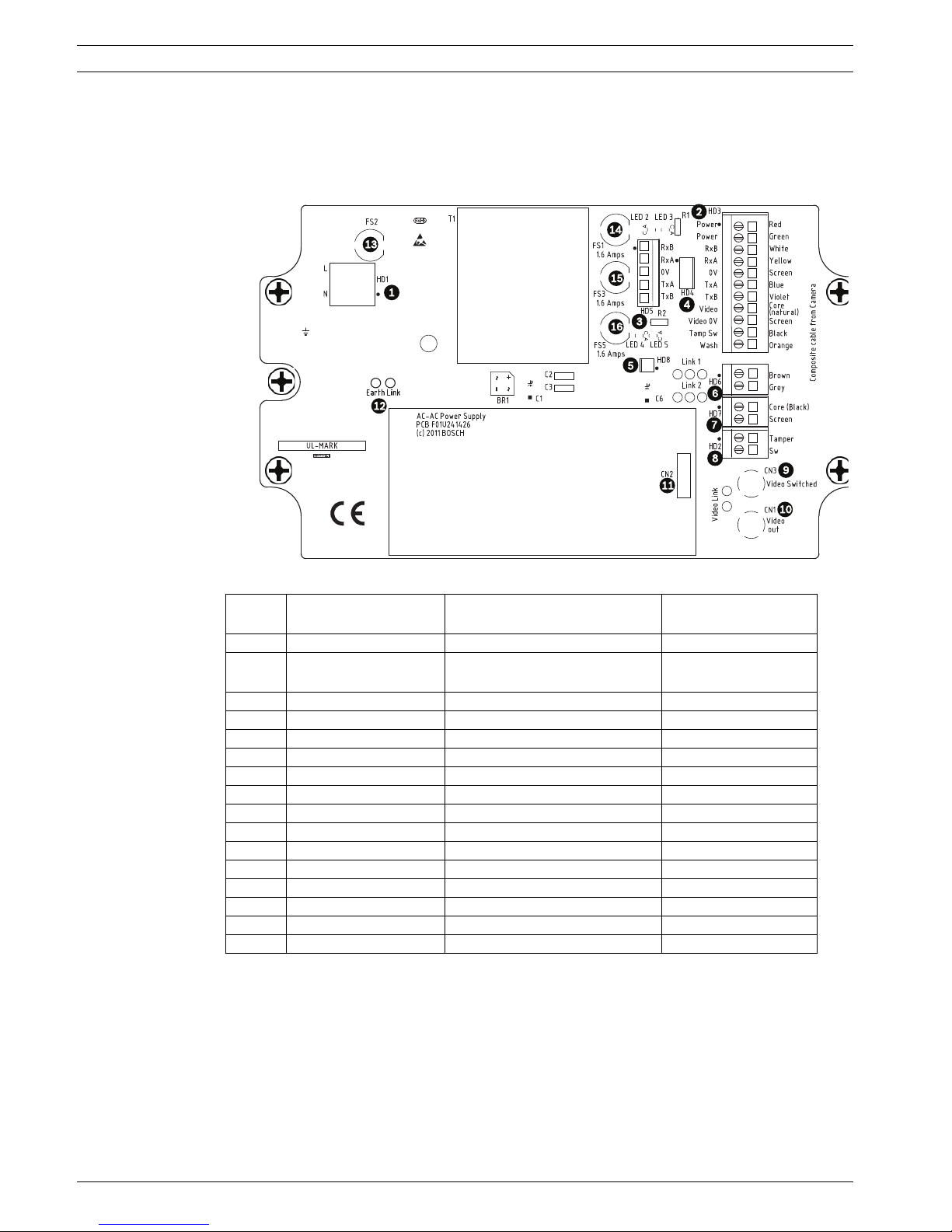
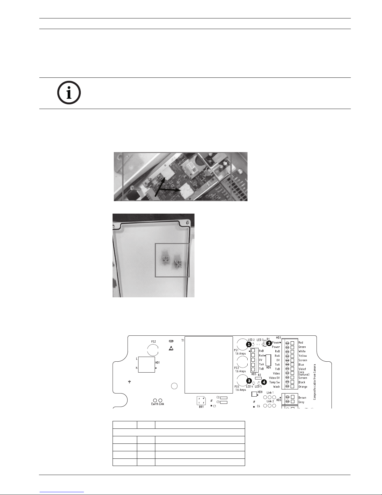
3.3 MIC Power Supply Units (PSUs) for Non-IR MIC Cameras
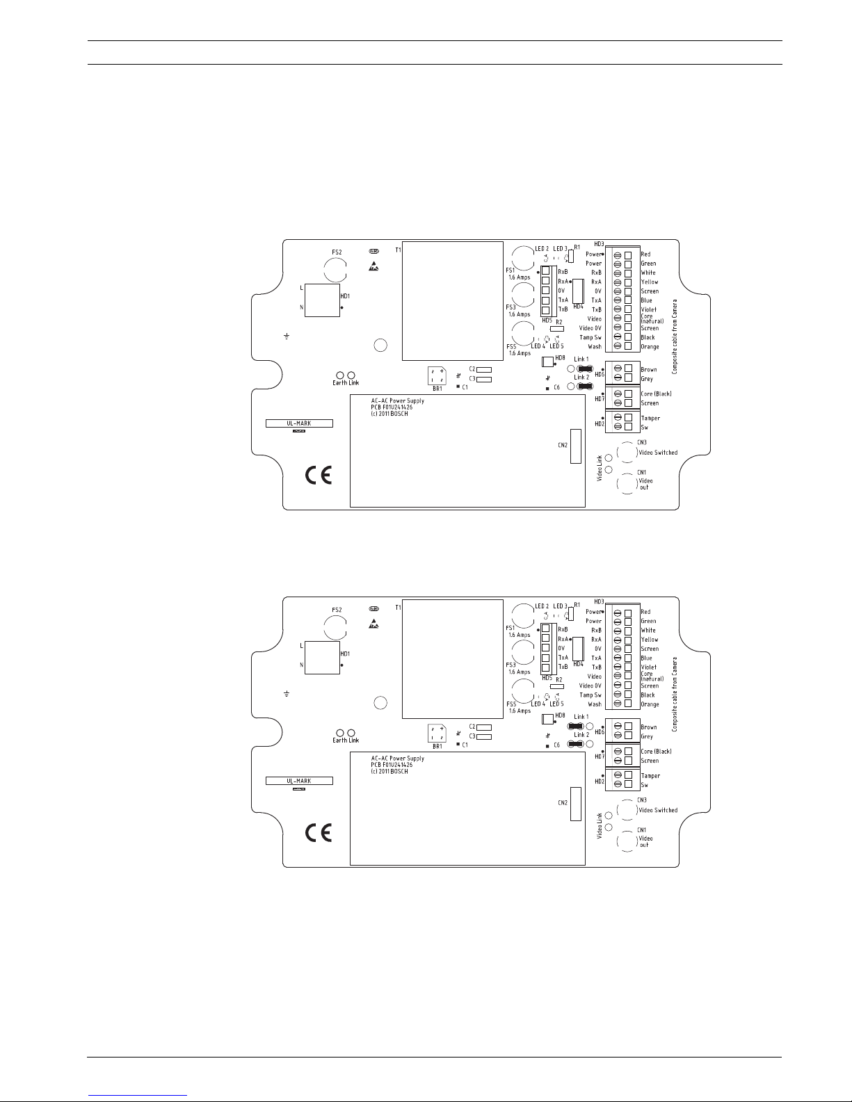
The figure below displays the layout of the PCB in the MIC PSUs for non-IR cameras, with callout numbers to the side of or below the connection/terminal ID or the terminal, and ’on’ the
fuses. The table below the figure identifies the connections.
Figure 3.3 Layout of PCB in enclosure of PSU for non-IR MIC cameras
Number Connection /
Terminal ID on PCB
Description/Function of
Connection / Terminal
Type of Connection /
Terminal
1 HD1 AC Power input Screw terminal
2 HD3 Shielded composite cable
(analog connections to camera)
Screw terminal
3 HD5 RS-485 control Screw terminal
4 HD4 USB to RS-485 converter Molex connector
5 HD8 **NOT USED** Molex connector
6 HD6 [Optional] Auxiliary, heater Screw terminal
7 HD7 Video (composite cable) Screw terminal
8 HD2 Tamper switch Screw terminal
9 CN3 (Video Switched) Coax connection BNC socket
10 CN1 (Video Out) Coax connection BNC socket
11 CN2 Auxiliary card header Plug in
12 Earth Link Earth Link -13 FS2 Fuse 2 - Primary protection -14 FS1 Fuse 1 - MIC camera protection -15 FS3 Fuse 3 - Heater protection 1 -16 FS5 Fuse 5 - Heater protection 2 --
MIC Series IP Power Supply Installation | en 15
Bosch Security Systems, Inc. User Manual F.01U.265.804 | 1.6 | 2012.08
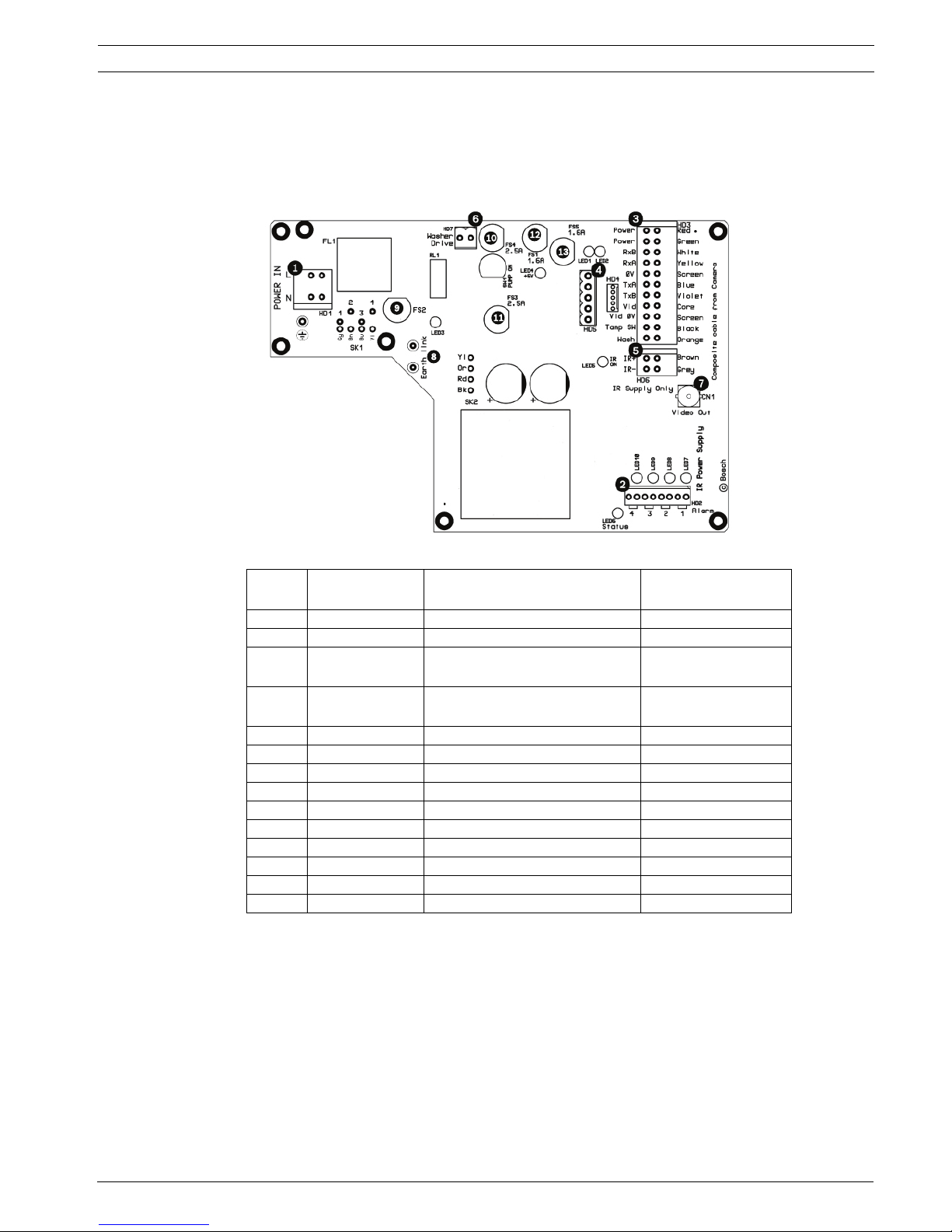
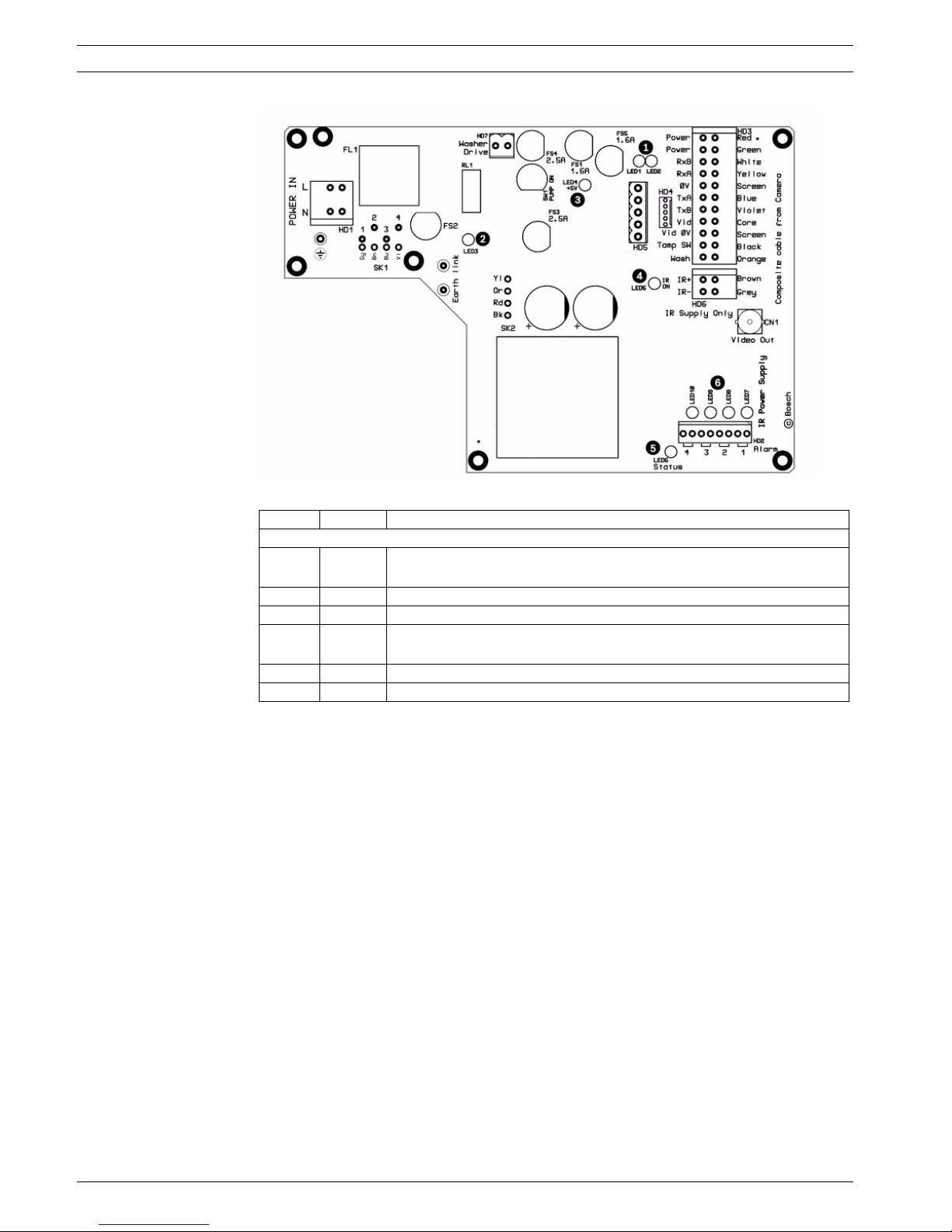
3.4 MIC Power Supply Units (PSUs) for IR MIC Cameras
The figure below displays the layout of the PCB in the MIC PSUs for IR cameras, with call-out
numbers to the side of or below the connection/terminal ID or the terminal, and ’on’ the
fuses. The table below the figure identifies the connections.
Figure 3.4 Layout of PCB in enclosure of PSU for MIC IR cameras
3.5 Earth Link on the PCB
The printed circuit board (PCB) of each MIC PSU (IR and non-IR) has one Earth Link option,
near terminal block HD1, to allow the PSU to be set up for different earthing schemes:
– If there is a separate connection between video screen and earth, the Earth Link should
be broken. This usually occurs on copper-connected systems where all of the copper
video coaxes are taken back to the control room to be connected to a central earth point.
– If fiber optics or other indirect connections are used to get data and video to and from
the control room, then the Earth Link should be left intact, as long as it is the only
camera-end earth reference point.
Number Connection /
Terminal ID
Description/Function of
Connection / Terminal
Type of Connection /
Terminal
1 HD1 AC Power input Screw terminal
2 HD2 4-input alarm Screw terminal
3 HD3 Shielded composite cable
(analog connections to camera)
Screw terminal
4 HD4 USB to RS-485 converter Screw terminal or
Molex connector
4 HD5 RS-485 control
5 HD6 [Optional] Auxiliary, IR lamps Screw terminal
6 HD7 Washer drive Screw terminal
7 CN1 (Video Out) Coax connection BNC socket
8 Earth Link Earth Link -9 FS2 Fuse 2 - Primary protection -10 FS4 Fuse 4 - washer drive -11 FS3 Fuse 3 - IR lamps -12 FS1 Fuse 1 - MIC camera protection -13 FS5 Fuse 5 - MIC camera protection --
16 en | Installation MIC Series IP Power Supply
F.01U.265.804 | 1.6 | 2012.08 User Manual Bosch Security Systems, Inc.
3.6 Fuse Ratings
Non-IR MIC power supplies have four (4) off 20 mm fuses (numbers 13 - 16 in Figure 3.3) in
fuse holders. The ratings for these fuses are fixed on the low voltage secondary side but
change with input voltage on the high voltage primary side. The following table shows the fuse
values that should be fitted to provide proper protection for the power supplies. Note: Fuse
FS4 does not exist.
MIC IR power supplies have five (5) 20 mm fuses (see Figure 3.4). The following table shows
the fuse values that should be fitted to provide proper protection for the power supplies.
Fuse IDFuse Function Type Ratings for 240 V
Primary
Ratings for 115 V
Primary
Ratings for 24 V
Primary
FS1 MIC camera protection Glass 1.6 A
anti-surge (T)
1.6 A glass
anti-surge (T)
1.6 A glass
anti-surge (T)
FS2 Primary protection Glass normal 250V 0.5A
5x20mm
normal 250V 0.8A
5x20mm
2.5 A quick blow
FS3 Heater protection 1 Glass 1.6 A
anti-surge (T)
1.6 A glass
anti-surge (T)
1.6 A glass
anti-surge (T)
FS5 Heater protection 2 Glass 1.6 A
anti-surge (T)
1.6 A glass
anti-surge (T)
1.6 A glass
anti-surge (T)
Fuse
ID
Fuse Function Type Ratings for 240 V
Primary
Ratings for 115 V
Primary
Ratings for 24 V
Primary
FS1 MIC camera protection Glass 1.6 A quick blow 1.6 A quick blow 1.6 A quick blow
FS2 Primary protection Glass 600 mA quick blow 1.0 A quick blow 2.5 A quick blow
FS3 IR lamps Glass 2.5 A quick blow 2.5 A quick blow 2.5 A quick blow
FS4 washer drive Glass 2.5 A quick blow 2.5 A quick blow 2.5 A quick blow
FS5 MIC camera protection Glass 1.6 A quick blow 1.6 A quick blow 1.6 A quick blow
CAUTION!
Replace only with the same type and rating of fuse for continued protection against the risk of
fire, damage or injury. Fitting fuses other than those described above invalidates the product
warranty and may result in damage to the product or injury to the installer.
MIC Series IP Power Supply Installation | en 17
Bosch Security Systems, Inc. User Manual F.01U.265.804 | 1.6 | 2012.08
3.7 Installation Instructions
To install the power supply, follow these steps:
1. Select the mounting position of the MIC PSU so that the PSU cannot be interfered with
either intentionally or accidentally. Bosch recommends using a lockable cabinet.
2. Loosen the four (4) captive Phillips head screws on the top of the lid of the power supply
enclosure (item 11, Figure 3.1). Lift the lid and set it upside down next to the enclosure.
CAUTION!
Installation must be made by qualified personnel and conform to ANSI/NFPA 70 (the National
Electrical Code
®
(NEC)), Canadian Electrical Code, Part I (also called CE Code or CSA C22.1),
and all applicable local codes. Bosch Security Systems, Inc. accepts no liability for any
damages or losses caused by incorrect or improper installation.
DANGER!
– ELECTRICAL SHOCK HAZARD
To reduce the risk of electrical shock, disconnect power before opening or working on
any power supply unit. Power must be disconnected before replacing any fuse in the MIC
PSU. Power supply units have power supplied whenever the power cord is inserted into
the power source.
– MIC PSUs have a separate internal shield covering the power cable input terminal block
(HD1). Only suitably qualified persons should remove this shield and connect the mains
power cable. The shield MUST be re-installed and fully secured before connecting the
power.
– The power supply cable shall have conductors of a maximum size of 12 AWG.
– Branch circuit protection is required. A readily accessible 2-pole disconnect device with a
contact separation of at least 3mm must be incorporated externally to the equipment.
WARNING!
To meet UL standards and ratings, all external wires for installation applications must be
routed through a permanently earthed metal conduit.
CAUTION!
– Do not connect MIC IR units to a MIC PSU with the heater option enabled as this can
result in damage to the cameras. Ensure that an IR power supply is used with a MIC IR
camera unit. Heaters are available for MIC612 cameras only.
– Except for the Earth Link, heater links (MIC612), and applicable fuse, the MIC PSUs have
no user-adjustable parts. MIC cameras have no user-serviceable parts.
– Bosch recommends using an uninterruptible power supply (UPS) in connection with a
MIC camera/PSU installation.
– MIC PSU enclosures are not EXD rated and must be replaced with a certified enclosure if
installed within a hazardous area.
NOTICE!
To maintain the IP (protection) rating of the power supply enclosure, install only listed or
recognized conduit hubs or fittings with the same environmental rating as the enclosure in
compliance with the installation instruction of the hub or fitting.
18 en | Installation MIC Series IP Power Supply
F.01U.265.804 | 1.6 | 2012.08 User Manual Bosch Security Systems, Inc.
3. Locate the four (4) mounting holes of the PSU (see Figure 3.5). The dimensions shown
are for the mounting holes only. The other four (4) holes shown are for securing the lid.
Figure 3.5 MIC IP PSU Mounting Dimensions
4. Drill four (4) holes in the mounting surface for the mounting anchors appropriate for M6
screws (not supplied).
5. Secure the PSU to the mounting surface using four (4) M6 stainless steel screws and
washers (not supplied).
6. Undo the two (2) M3 screws on the internal high voltage input head-end shield (marked
with "Danger") covering the power cable terminal HD1; retain the screws.
7. Remove the internal shield and set it nearby, outside of the PSU enclosure.
8. Remove the blanking plug covering the hole for the power cable (item 6, Figure 3.1).
Install suitable (metal) conduit (not supplied) in the hole. Secure the conduit as
recommended by the conduit manufacturer.
NOTICE!
– Do not stretch or cut, or otherwise disturb, the earth core cable to the inside of the lid
and to the earth termination post . (See Figure 3.6.)
– Note the position of the thermal pads. They should be sticking onto either the built-in
stand-offs on the inside of the lid of the enclosure, or onto designated spots on the
encoder. If the pads are not positioned correctly, they can cause the encoder to stop
functioning properly. See Figure 3.9 and Figure 3.10 for details.
NOTICE!
If you are securing the power supply enclosure in a vertical position (for example, on a wall),
one person should hold the enclosure lid while another secures the enclosure body in place,
to avoid damage to any part of the enclosure, and/or injury to the installer(s).
CAUTION!
Only installations with conduit meet UL standards. If you choose to use a power cord without
conduit (not recommended), fit the 1/2 in. NPT cable gland (supplied) in place of the blanking
plug. It is easier to fit the power cord through the cable gland outside of the enclosure, and
then attach the gland to the enclosure. Ensure that the cable gland has sufficient room to
allow for the cable to enter (approximately 60 mm on either side of the enclosure).
MIC Series IP Power Supply Installation | en 19
Bosch Security Systems, Inc. User Manual F.01U.265.804 | 1.6 | 2012.08
9. Prepare the power cable as needed, and then feed the cable into the enclosure.
10. Connect the Live and Neutral cores to the correct screw terminals on terminal block HD1
as identified in the table below and printed on the PCB. Observe polarity and voltage.
11. Remove the brass nut and copper washer from the earth termination post (item 3,
Figure 3.6); set these aside.
Figure 3.6 Power (mains) input with shield removed, showing terminal block HD1 before wiring
12. Remove the ring terminal (supplied).
13. Insert the earth core from the mains cord (item 2, Figure 3.6) into the crimp portion (size
M6, UL-certified) of the ring terminal and crimp it in place.
Note: The graphic in the figure referenced below is representative of the connections;
the layout of the MIC IP PSU differs slightly from that depicted below.
14. Place the ring terminal onto the earth termination post.
15. Replace the copper washer. Secure with the brass nut.
16. Replace the internal shield, taking care to avoid pinching the cables. Tighten the screws.
* If connecting a heater [MIC612 only], see Section 3.8 Commissioning the Camera with Heater
Option Fitted.
17. On non-IR models only: If necessary, connect a tamper switch to terminal block HD2.
18. If simultaneous video (IP and analog (PAL or NTSC)) is desired, follow these steps:
a. Disconnect the coax cable between the BNC socket (marked "VIDEO IN") on the
encoder and the BNC socket CN1 on the PCB.
b. Attach a BNC "T" connector (75 ohm, user-supplied) to the BNC socket CN1 on the
PCB.
c. Re-attach the coax cable from the encoder to one end of the "T" connector.
PCB Marking Description
LLive
N Neutral
Earth / Ground
Number Description
1 Earth core cable to enclosure lid
2 Earth core cable to power supply PCB
3 Earth termination post
NOTICE!
For MIC612 cameras only: You must connect the overall shield drain wire of the composite
cable to the power supply chassis in order to ground the chassis. Crimp the drain wire to the
ring terminal lug attached to the mounting screw of the PCB located to the right of BNC
socket CN3 (Video Switched). See Figure 3.3 for location of the screw.
20 en | Installation MIC Series IP Power Supply
F.01U.265.804 | 1.6 | 2012.08 User Manual Bosch Security Systems, Inc.
d. Feed your coax cable coming from Bilinx-compatible head-end control system through
the top-left M12 cable gland (item 1, Figure 3.7).
e. Attach your coax cable to the other end of the "T" connector.
f. After the PSU is operational, you must access the menu for Encoder settings and
disable the video termination option. See Section 4.17 Video Input of the User Manual.
Figure 3.7 Enclosure of MIC IP PSU, with cable glands identified
19. On non-IR power supplies for non-thermal cameras: If connecting to additional add-on
cards (for example, a card for 8-input alarms plus washer pump drive (MIC-ALM)),
remove the blanking plug that covers the hole for the bottom-left M12 cable gland (item
3, Figure 3.7). Attach the supplied M12 gland. Make the appropriate connections to plugin terminal CN2.
20. Through the top right hole (item 2, Figure 3.7) of the enclosure, install conduit necessary
to protect standard UTP category 5 cable.
Note: You may need to remove the cable gland first.
21. Feed the category 5 cable through the conduit and into the enclosure.
22. Connect the RJ45 plug of the cable to the ETH socket on the encoder to connect the
encoder to the network.
Note: If installing a fiber optic module, see the Fiber Optic Media Converter Installation
Guide for instructions for installing the module in the MIC IP PSU.
Number Description Cable Gland Size
1 Composite cable (used for analog connections) 1/2 in.
2 RJ45 / Fiber cable M16
3 For non-thermal cameras: Optional cable gland for alarms
For thermal cameras: optional switched video output
M12
4 Cable gland for optional washer drive M12
MIC Series IP Power Supply Installation | en 21
Bosch Security Systems, Inc. User Manual F.01U.265.804 | 1.6 | 2012.08
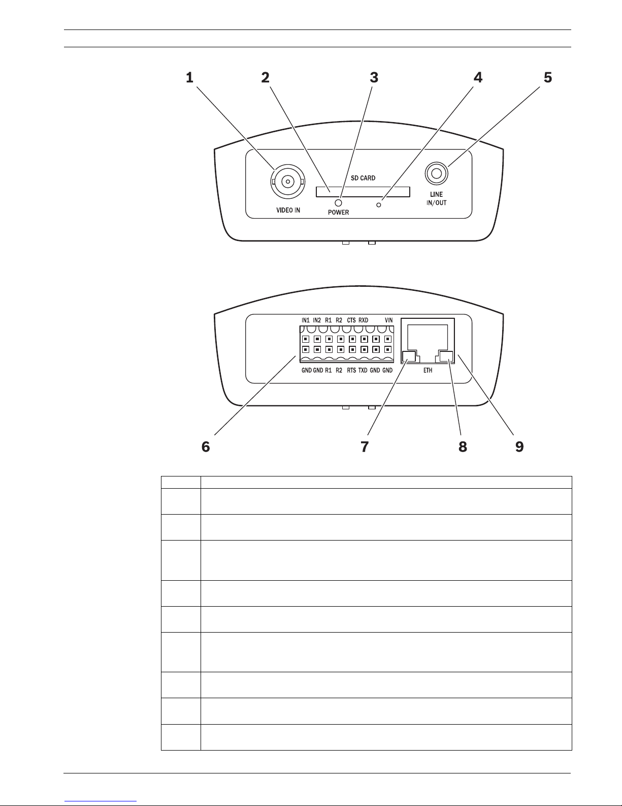
Figure 3.8 Encoder connections front (top half of graphic) and back (bottom half of graphic)
Number Description
1 VIDEO IN video input
BNC socket (75 ohm) for connecting the video source
2 SD CARD slot
(The release letter of the current firmware version has a list of compatible cards.)
3 POWER LED
lights up green when ready for operation
(See "LEDs" in the User Manual for more information about the LEDs.)
4 Factory reset button
to restore factory default settings
5 LINE IN/OUT
For audio connection (not applicable to MIC cameras)
6 Terminal Block
for alarm inputs, relay outputs, serial interface and power supply
(See "Terminal block" in the Appendix of the User Manual for details.)
7 Green LED
lights up when the unit is connected to the network
8 Orange LED
lights up during data transmission
9 ETH RJ45 socket
for connecting to an Ethernet LAN (local network), 10/100 MBit Base-T
22 en | Installation MIC Series IP Power Supply
F.01U.265.804 | 1.6 | 2012.08 User Manual Bosch Security Systems, Inc.
23. Make the connections for Alarm inputs as needed.
- For IP connections, connect the lines for the alarm inputs (for external devices such as
door contacts or sensors) to terminals IN1 and IN2 on the orange terminal block (see the
section "Terminal block" in the Appendix of the User Manual) of the encoder, and check
that the connection is secure. Connect each alarm input to a ground contact (GND). With
the appropriate configuration, an alarm sensor can automatically connect the encoder to
a remote location, for example.
Note: You can use a zero potential closing contact or switch as the actuator.
If possible, use a bounce-free contact system as the actuator.
- For physical alarm connections on MIC IR power supplies, connect alarm input cables to
terminal block HD2, as indicated in the table below:
24. Make the connections for Relay outputs as needed. Connect the lines for the relay
outputs (for switching external units such as lamps or alarm sirens) to terminals R1 and
R2 on the orange terminal block of the encoder, and check that the connection is secure.
You can operate these relay outputs manually while there is an active connection to the
encoder. The outputs can also be configured to activate sirens or other alarm units
automatically in response to an alarm signal.
25. To save recordings locally, insert an SD card into the slot SD CARD of the encoder by
carefully sliding the card into the slot as far as it will go, until it locks into place.
(To remove the card, push carefully in the direction of insertion until the mechanical
catch releases, and then remove the card.)
26. On MIC IR power supplies, a washer drive is standard. A 24 VAC rated relay is fitted via the
onboard fuse FS4 (rated at 2.5 Amps). Make the following washer pump connections to
terminal block HD7 (marked Washer Drive on the PCB):
Signal Pin Number
Alarm 1 1
0 V 2
Alarm 2 3
0 V 4
Alarm 3 5
0 V 6
Alarm 4 7
0 V 8
CAUTION!
A maximum load of 30 V
p-p
and 200 mA (SELV) may be applied to the relay contacts.
CAUTION!
If the card is formatted already, all existing data will be deleted from the card! Before
inserting the card, check whether the SD card contains any data that must be backed up.
Signal Pin Number
Washer Pump 1
Washer Pump 2
WARNING!
The washer pump terminal is rated only to 24 VAC or VDC maximum voltage and is not
suitable for Mains-operated pumps.
MIC Series IP Power Supply Installation | en 23
Bosch Security Systems, Inc. User Manual F.01U.265.804 | 1.6 | 2012.08
27. Test the washer by pressing the red button marked SW1 PUMP ON on the PCB.
LED 3 illuminates in response to telemetry commands from the control room to turn on
the washer. Note that the software in the camera prevents the washer from running more
than 10 seconds continuously to prevent emptying the washer bottle.
28. Verify that the thermal pads are in the correct position on the encoder or on the built-in
stand-offs on the inside of the lid of the enclosure. Correct positioning of the thermal
pads is imperative, or the encoder may not function. See the photos below for the
correct positioning.
Figure 3.9 Thermal pads in correct position on the encoder
Figure 3.10 Location of correct position for thermal pads on the inside of the lid of the enclosure
29. After all wiring and connections are complete, connect the power supply to the power
source. The PSU should now have power and be operational.
30. Verify that the following LEDs are lit on the PCB (depending on the model of MIC PSU):
Figure 3.11 MIC Series power supply LED position (at the "top right" of the PCB)
NOTICE!
For installation of the MIC Washer Kit (MIC-WKT), MIC 8-input Alarm Card (MIC-ALM) or
Biphase converters (MIC-BP3 or MIC-BP4), please see their respective manuals.
Number LED Description
MIC Non-IR models
1 LED 2 18 VAC power on to camera
2 LED 4 Power on for optional heater
3 LED 3 18 VAC power on camera
4 LED 5 Power on for optional heater
24 en | Installation MIC Series IP Power Supply
F.01U.265.804 | 1.6 | 2012.08 User Manual Bosch Security Systems, Inc.
Figure 3.12 MIC Series IR power supply LED positions
31. Re-attach the enclosure lid and tighten the four (4) captive screws on the lid to ensure
that the enclosure is watertight.
Number LED Description
MIC IR models
1LED 1
LED 2
Indicates that 18 VAC is available from the power supply and that
the supply fuses are intact.
2 LED 3 Illuminates when the washer drive is on.
3 LED 4 Monitors the internally generate +5 V.
4 LED 5 Illuminates when the IR lamp supply is turned on by the camera
telemetry.
5 LED 6 Status LED. Pulses On/Off when Multi Alarm is selected.
6 LED 7-10 Illuminate when the associated alarm is active.
MIC Series IP Power Supply Installation | en 25
Bosch Security Systems, Inc. User Manual F.01U.265.804 | 1.6 | 2012.08
3.8 Commissioning the Camera with Heater Option Fitted
To enable the heaters for MIC612, you must change two links on the PCB of the power supply.
Follow these steps:
1. Disconnect the power supply from the power source.
2. Open the power supply enclosure.
3. Locate Link 1 and Link 2 on the PCB, next to terminal block HD6. The default setting is
0V.
Figure 3.13 PCB links set to 0V
4. Break the two solder links. Remove any excess solder.
5. Solder the links, using TCW link wire, from the left hand pads to the middle pads. The
power supply will now deliver 18 VAC to terminal block HD6.
Figure 3.14 PBC links set to 18V
6. Locate the Brown and Grey wires from the composite cable.
7. Connect the heater wires Brown and Grey to terminal block HD6 as labelled on the PCB.
The heaters are thermostatically controlled and will automatically turn on at +5 °C (+41
°F) and turn off at +15 °C (+59 °F).
8. Check all connections.
9. Close the PSU enclosure.
10. Reconnect the power supply to the power source.
26 en | Installation MIC Series IP Power Supply
F.01U.265.804 | 1.6 | 2012.08 User Manual Bosch Security Systems, Inc.
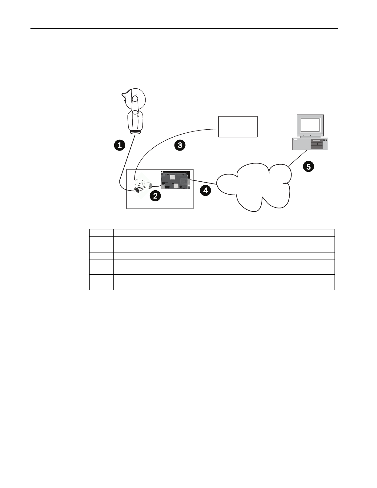
3.9 Simultaneous IP and Analog Video/Control ("Hybrid"
Operation)
The figure below illustrates how to configure your system to achieve simultaneous video and
control over both IP and analog connections.
Figure 3.15 System configuration for simultaneous video/control
3.10 Assign an IP Address
Assign an IP address to the encoder. The encoder must have a valid IP address for your
network and a compatible subnet mask before you can operate it within your network.
1. If you have not already done so, install the Configuration Manager program from the
product CD.
2. Start Configuration Manager. The system automatically searches the network for
compatible units.
3. If the encoder is displayed in the list, right-click the entry, then select Device Network
Settings... from the popup menu that appears.
4. In the Device IP address field, enter the required IP address (for example 192.168.0.100)
and click OK. The encoder reboots and the IP address is valid.
Number Description
1 Connection between MIC camera and BNC T-connector in BNC socket on PCB in
MIC IP PSU
2 Connection between BNC T-connector and encoder in MIC IP PSU
3 Connection between BNC T-connector and Bilinx-based control (head-end) system
4 Connection between encoder and Local Area Network (LAN) (or the "cloud")
5 Connection between the Local Area Network (LAN) (or the "cloud") and PC
connected to video monitor
Bilinx

MIC Series IP Power Supply Installation | en 27
Bosch Security Systems, Inc. User Manual F.01U.265.804 | 1.6 | 2012.08
3.11 Hardware connections between video servers
An encoder with a camera connected to it can be used as a sender and a compatible hardware
decoder (such as the VIP XD) with a connected monitor as a receiver using an Ethernet
network connection. In this way it is possible to cover long distances without the need for
major installation or cabling work.
Installation
Compatible video servers are designed to connect to one another automatically, provided
they are correctly configured. They only need to be part of a closed network. Proceed as
follows to install the units:
1. Connect the units to the closed network using Ethernet cables.
2. Connect them to the power supply.
Connecting
There are three options for establishing a connection between a sender and a compatible
receiver in a closed network: an alarm, a terminal program, or Internet Explorer.
Connecting on alarm
With the appropriate configuration, a connection between a sender and a receiver is made
automatically when an alarm is triggered (see Section 4.38 Alarm Connections, page 65). After
a short time the live video image from the sender appears on the connected monitor. This
option can also be used to connect a sender and a compatible receiver using a switch
connected to the alarm input. You do not need a computer to make the connection in this
case.
Connecting with a terminal program
Various requirements must be met in order to operate with a terminal program (see
Section 6.11 Communication with terminal program, page 95).
1. Start the terminal program and enter the command 4 in the main menu to switch to the
Rcp+ menu.
2. Enter the command c in the Rcp+ menu to change the remote IP address, then enter the
IP address of the unit you wish to connect to.
3. In the Rcp+ menu, enter command 1 to activate automatic connection.
Closing the connection with a terminal program
1. Start the terminal program and enter the command 4 in the main menu to switch to the
Rcp+ menu.
2. In the Rcp+ menu, enter command 3 to deactivate automatic connection.
NOTICE!
The sender and receiver must be located in the same subnet to establish a hardware
connection.
NOTICE!
Make sure that the units are configured for the network environment and that the correct IP
address for the remote location to be contacted in the event of an alarm is set on the Alarm
Connections configuration page (see Section 4.38 Alarm Connections, page 65).
NOTICE!
Connecting with a Web browser is described in the manual of the relevant unit that is to be
used as the receiver, for example VIP XD.

28 en | Configuration using a Web browser MIC Series IP Power Supply
F.01U.265.804 | 1.6 | 2012.08 User Manual Bosch Security Systems, Inc.
4 Configuration using a Web browser
4.1 Connecting
A computer with Microsoft Internet Explorer (version 7.0 or higher) can receive live images
from the encoder, control cameras or other peripherals and replay stored video sequences.
Before you can operate the camera via the encoder, you must configure the camera.
The integrated HTTP server in the encoder provides you with the option to configure the unit
over the network with a Web browser. This option is an alternative to configuration using the
Configuration Manager application (version 4.21 or higher) and is considerably richer in
function and more convenient than configuration using the terminal program.
4.1.1 System Requirements
– Computer with Windows XP or Windows 7 operating system
– Network access (Intranet or Internet)
– Microsoft Internet Explorer (version 7.0 or higher)
– Screen resolution at least 1,024 × 768 pixels
– 16- or 32-bit color depth
– Installed Java Virtual Machine (JVM)
4.1.2 Additional Operational Requirements
– Instead of Microsoft Internet Explorer:
Receiver software (such as Bosch Video Management System (version 3.0 or higher)) OR
H.264-compatible hardware decoder from Bosch Security Systems (such as VIP XD HD)
as a receiver and connected video monitor
– For playing back recordings: connection to storage medium [a different encoder from the
one built-in to the power supply enclosure]
4.1.3 Installing MPEG ActiveX
Suitable MPEG ActiveX software must be installed on the computer to allow the live video
images to be played back. If necessary, you can install the program from the product CD
supplied.
1. Insert the product CD into the computer's CD-ROM drive. If the CD does not start
automatically, open the root directory of the CD in Windows Explorer and double-click
MPEGAx.exe.
2. Follow the on-screen instructions.
4.1.4 Establishing the Connection
Before you can operate the encoder within your network, it must have a valid IP address for
your network and a compatible subnet mask.
The following default address is preset at the factory: 192.168.0.1
1. Start the Web browser.
2. Enter the IP address of the encoder as the URL.
NOTICE!
Also note the information in the System Requirements document on the product CD
supplied. If necessary, you can install the required programs and controls from the product
CD supplied.
The Web browser must be configured to enable Cookies to be set from the IP address of the
unit.
In Windows 7, deactivate protected mode on the Security tab under Internet Options.
You can find notes on using Microsoft Internet Explorer in the online Help in Internet Explorer.

MIC Series IP Power Supply Configuration using a Web browser | en 29
Bosch Security Systems, Inc. User Manual F.01U.265.804 | 1.6 | 2012.08
3. During initial installation, confirm the security questions that appear. The connection is
established and after a short time you will see the LIVEPAGE with the video image.
Maximum number of connections
If you do not connect, the unit may have reached its maximum number of connections.
Depending on the unit and network configuration, each encoder can have up to 25 Web
browser connections or up to 50 connections via Bosch Video Management System.
Protected Encoder
If the encoder is password protected against unauthorized access, the Web browser displays
a corresponding message and prompts you to enter the password when you attempt to
access protected areas.
1. Enter the user name and associated password in the corresponding text fields.
2. Click OK. If the password is entered correctly, the Web browser displays the page that
was called up.
Protected network
If a RADIUS server is employed in the network for managing access rights (802.1x
authentication), the encoder must be configured accordingly, otherwise no communication is
possible.
To configure the unit, you must connect the encoder directly to a computer using a network
cable. This is because communication via the network is not enabled until the Identity and
Password parameters have been set and successfully authenticated (see
Section Authentication, page 76).
NOTICE!
The encoder offers the option to limit the extent of access using various authorization levels
(see Section 4.10 Password, page 37).
30 en | Configuration using a Web browser MIC Series IP Power Supply
F.01U.265.804 | 1.6 | 2012.08 User Manual Bosch Security Systems, Inc.
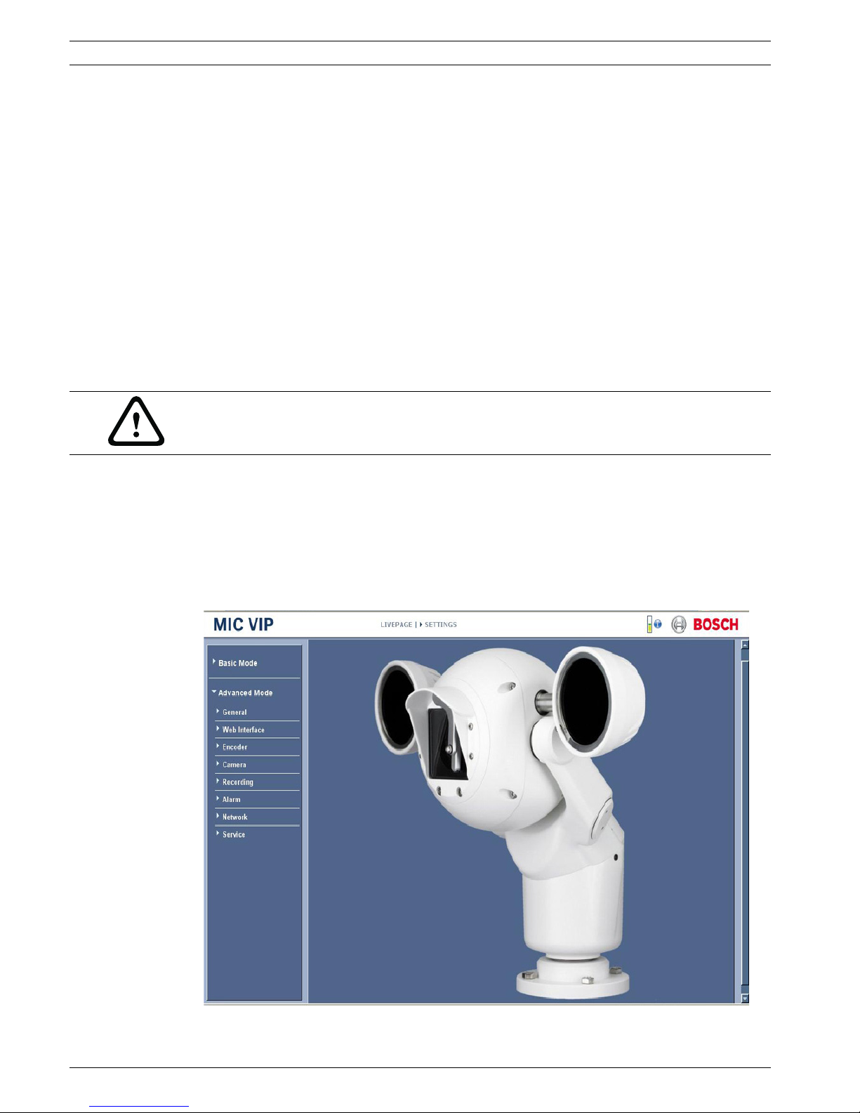
4.2 Configuration menu
The SETTINGS page provides access to the configuration menu, which contains all the unit's
parameters arranged in groups. You can view the current settings by opening one of the
configuration screens. You can change the settings by entering new values or by selecting a
predefined value from a list field.
There are two options for configuring the unit or checking the current settings:
– Basic Mode
– Advanced Mode
In Basic Mode the most important parameters are arranged in seven groups. This allows you
to change the basic settings with just a few entries and then put the device into operation.
Advanced Mode is recommended for expert users or system support personnel. You can
access all device parameters in this mode. Settings that affect the fundamental functionality
of the device (such as firmware updates) can only be altered in Advanced Mode.
All parameter groups are described in this chapter in the order in which they are listed in the
configuration menu, from the top of the screen to the bottom.
All settings are backed up in the encoder memory so they are not lost even if the power fails.
The exception is the time settings, which are lost after 72 hours without power if no central
time server is selected (see Section 4.4 Basic Mode: Date/Time, page 32).
Starting configuration
Click the SETTINGS link in the upper section of the window. The Web browser opens a
new page with the configuration menu.
CAUTION!
The settings in the Advanced Mode should only be processed or modified by expert users or
system support personnel.
 Loading...