


Bosch MIC440AXWUW14636N, MIC440AXWUW14618N, MIC440AXWUP14618N, MIC440AXWUL14636N, MIC440AXWUA14636N User Manual
...MIC440 Explosion Protected
CCTV Camera System
Bosch Security Systems
EN Installation and Operation Manual
MIC440 Explosion Protected CCTV
Camera System
Installation and Operation Manual
For the MIC440 Camera System
Chapters
1.Introduction
2.Hardware Installation
3.Power Supply Installation & Setup
4.Configuring the MIC440 Camera
5.Technical Specifications

MIC440 Explosion Protected CCTV Camera System| Installation and Operation Manual |
EN | 3 |
Introduction............................................................... |
1-6 |
MIC440 Camera Options..................................................................... |
1-7 |
MIC440 Power Supply Versions……………………………………….... 1-7 |
|
Unpacking............................................................................................ |
1-8 |
Package Contents............................................................................... |
1-8 |
Installation Accessories....................................................................... |
1-9 |
Hardware Installation................................................ |
2-10 |
Preinstallation Preparation in the Workshop……………………..…….. 2-11 Cable Gland and Cable Mounting Instructions………..……………….. 2-11
Camera Installation Instructions........................................................... |
2-11 |
Electrical Connections to the MIC440.................................................. |
2-12 |
Earthing Instructions............................................................................ |
2-13 |
Lightning Protection............................................................................. |
2-13 |
Maintenance….……………..……………………………………….…….. 2-13 |
|
Onsite Inspection..…………………….................................................. |
2-13 |
Power Supply Installation and Setup…..................... 3-14
Hazardous Area Power Supply Installation………..…………………… 3-14 Diagrams of example Hazardous Area Installations…………………... 3-15
Non Hazardous area Power Supply Installation........................……… |
3-16 |
Connecting the MIC-240, MIC-24 and MIC115PSU….……………….. |
3-17 |
Power Supply Layout and Connections............................................... |
3-18 |
PCB Earth Link………......................................................................... |
3-18 |
Fuse Ratings………………………………………….............................. |
3-18 |
MIC-12PSU….…………………………................................................. 3-19 |
|
MIC-12PSU Power Supply Layout and Connections........................... |
3-19 |
Optional Cards and Kits for the MIC440………………………………... 3-20
Configuring the MIC440 Camera……………………. 4-20
Connecting the MIC440 to a PC.......................................................... |
4-20 |
Connecting the Greenwich adaptor……………………………………... 4-20 Connecting the K2-ADE Adaptor………………………………………... 4-21 Connecting the MIC-USB485 Converter……………………………….. 4-22 MIC-USB485 Converter and Universal Camset Software Installation. 4-22 Commissioning the MIC440 camera with Universal Camset………… 4-23
Standard Controls.………………………………………………………… 4-23 Boot Messaging…………………………………………………………… 4-24
MIC Settings……………………………………………………………….. 4-24
Camset Settings…………………………………………………………… 4-25
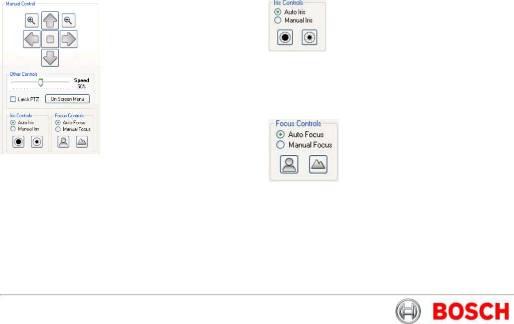
Manual Control.…………………………………………………………… 4-26
Pan, Tilt and Zoom Controls…………………………………………….... 4-26
Iris Controls………………………………………………………………… 4-26
Focus Controls…………………………………………………………….. 4-26
Auxiliaries………………………………………………………………….. 4-27
Preset Positions…………………………………………………………… 4-27
Tour Controls………………………………………………………………. 4-28
Softstops and No Dwell Zones…………………………………………… 4-28
MIC Setups………………………………………………………………… 4-29
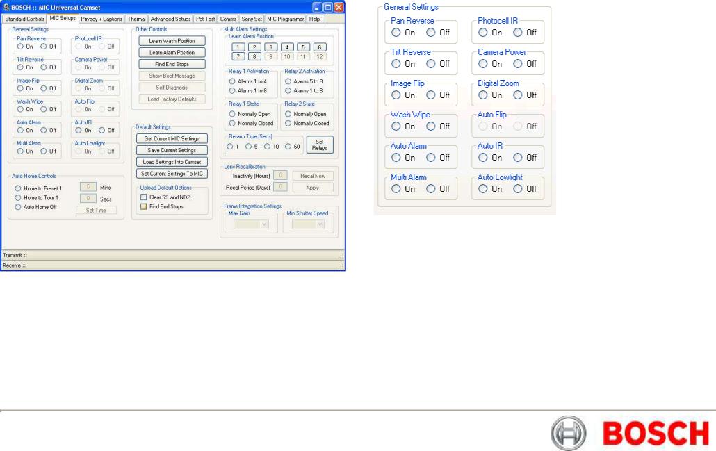
General Settings…………………………………………………………… 4-29
AutoHome Controls……………………………………………………….. 4-30
Other Controls……………………………………………………………… 4-31
Default Settings……………………………………………………………. 4-31
MultiAlarm Settings……………………………………………………….. 4-32
Lens Recalibration and Frame Integration……………………………… 4-33
Privacy and Captions……………………………………………………… 4-33
Privacy Controls…………………………………………………………… 4-34
Captions……………………………………………………………………. 4-35
Thermal…………………………………………………………………….. 4-36
Advanced Settings………………………………………………………… 4-37
MIC Serial Number………………………………………………………… 4-37
EEPROM Copier…………………………………………………………… 4-38
Re-Map Auxiliary (Pelco Protocol Only)…………………………………. 4-38
Menu Control (Panasonic Protocol Only)……………………………….. 4-39
Matrix Controls……………………………………………………………… 4-39
POT Test……………………………………………………………………. 4-39
POT Test Controls…………………………………………………………. 4-40
POT Test Results…………………………………………………………. 4-41
Comms…………………………………………………………………….. 4-41
Send Direct Command…………………………………………………… 4-42
Communications Testing…………………………………………………. 4-42
SonySet…………………………………………………………………….. 4-43
SonySet Controls………………………………………………………….. 4-44
The SonySet Table………………………………………………………... 4-45
MIC Programmer…………………………………………………………... 4-46
Technical Specifications.......................................... 5-47
Technical Specifications…………………………………………………. 5-47
Bosch Security Systems |
Issue 6 |
MIC440 Explosion Protected CCTV Camera System| Installation and Operation Manual |
EN | 4 |
Safety Precautions
The following symbols are used throughout this manual please pay careful attention to their meaning.
The lightning flash with an arrowhead symbol within a triangle is intended to alert the user to the presence of non-insulated “dangerous voltage” within the product’s enclosure that may be of sufficient magnitude to constitute a risk of electric shock to persons.
The exclamation point within a triangle is intended to alert the user to the presence of important safety, operating and maintenance (servicing) instructions in the literature accompanying the appliance.
Important Safety Instructions
CAUTION
TO REDUCE THE RISK OF ELECTRICAL SHOCK,
DISCONNECT POWER SUPPLY BEFORE OPENING THE
POWER SUPPLY UNIT.
POWER DISCONNECT: POWER SUPPLY UNITS HAVE
POWER SUPPLIED WHENEVER THE POWER CORD IS
INSERTED INTO THE POWER SOURCE
WARNING
INSTALLATION SHOULD BE CARRIED OUT BY QUALIFIED
PERSONNEL ONLY IN ACCORDANCE WITH THE
APPLICABLE LOCAL CODES.
BOSCH SECURITY SYSTEMS ACCEPT NO LIABILITY FOR
ANY DAMAGES OR LOSSES CAUSED DUE TO
INCORRECT OR IMPROPER INSTALLATION
Bosch Security Systems |
Issue 6 |
MIC440 Explosion Protected CCTV Camera System| Installation and Operation Manual EN | 5
|
IMPORTANT SAFETY INSTRUCTIONS |
|
|
WARNING |
|
||
1. |
Read and keep these instructions |
|
|
NO REPAIRS REQUIRING OPENING THE PRODUCT |
|
||
2. |
Heed all warnings and Follow all instructions |
|
|
CASING WHILST IN A HAZARDOUS AREA ARE |
|
||
3. |
Do not install near any strong heat sources such as furnaces |
|
|
ALLOWED. |
|
||
4. |
Do not back-drive the pan or tilt axis of the camera. To do so will damage |
|
|
FAILURE TO OBSERVE THIS PRECAUTION WILL VOID |
|
||
|
the motor drive gear chain and will invalidate the warranty |
|
|
THE CERTIFICATION AND WARRANTY. |
|
||
5. |
Do not use caustic or abrasive cleaning products on the unit |
|
|
BOSCH SECURITY SYSTEMS ACCEPTS NO LIABILITY |
|
||
|
|||||||
6. |
Do not point the MIC440 camera at the sun. BOSCH Group will not be liable |
|
|
FOR LOSSES CAUSED BY INCORRECT INSTALLATION |
|
||
|
for any damages to cameras which have been directly pointed at the sun |
|
|
OR MISUSE OF THE PRODUCT |
|
||
7. |
In situations where there could be a risk of injury should any part of the |
|
|
|
|
|
|
|
assembly become detached for any reason and fall, normal common sense |
Please contact BOSCH Security Systems for details of approved repair centres. |
|||||
|
safety precautions should be employed; a strong safety chain between the |
|
|
|
|
|
|
8. |
camera pan shaft and the mounting surface is recommended |
This product complies with the following EC directives:- |
|||||
For transportation please rotate the ball so the window points towards the |
|
|
|
|
|
||
|
base, this helps to protect the wiper & windows during transit |
EMC Directive (89/336/EC as amended) |
|||||
9. |
Ensure that the product case is properly earthed. If the product is likely to |
||||||
Machinery Directive (98/37/EC) |
|||||||
|
be struck by lightning, ensure that earth-bonding connections are made |
||||||
|
correctly to the mounting base of the unit |
LV Directive (73/23/EC) |
|||||
10. |
Use only the power sources indicated in this user guide and ensure that the |
|
|
|
|
|
|
|
current rating of supply cables, fuses and overload protection devices are |
RoHS (Restriction of Hazardous Substances) 2002/95/EC |
|||||
|
adequate for the product. |
|
|
|
|
|
|
11. |
The product is certified for use within the ambient temperature range of |
WEEE (Waste Electrical & Electronic Equipment) 2002/96/EC |
|||||
|
-20C to +60º C and must not be used outside this range. |
||||||
12. |
This product must only be installed by suitably trained personnel in |
|
|
|
|
|
|
|
accordance with the relevant code of practice (e.g. EN60079-14:1997). |
|
|
|
|
|
|
|
|
|
|
This equipment contains electrical or electronic |
|||
|
These instructions are intended for their sole use. |
|
|
|
|||
13. |
All installation work should be carried out in accordance with the relevant |
|
|
|
components that must be recycled properly to comply with |
||
|
|
|
Directive 2002/96/EC of the European Union regarding the |
||||
|
local and national standards.The unit shall only be installed and brought into |
|
|
|
|||
|
|
|
|
disposal of waste electrical and electronic equipment |
|||
|
service using the operating parameters defined in these instructions and in |
|
|
|
|||
|
the technical specifications. |
|
|
|
(WEEE). Contact your local supplier for procedures for |
||
|
|
|
|
recycling this equipment. |
|||
14. |
There are no user serviceable parts and on line maintenance is not required |
|
|
|
|||
|
for this product. |
|
|
|
|
|
|
|
This product is designed for use with flammable gases and vapors |
||||||
15. |
Inspection and maintenance of this equipment must be carried out by |
||||||
covered by apparatus groups IIA, IIB and IIC and with temperature |
|||||||
|
suitably trained personnel in accordance with the applicable code of |
||||||
|
practice e.g. EN 60079-17. |
classes T1 to T6. |
|||||
16.Repair of this equipment must be carried out by suitably trained personnel in accordance with the applicable code of practice e.g. EN 60079-19.
17.Units must carry the following certification marking.
SIRA05ATEX1300X Exd IIC T6 Ta –20ºC to +60ºC Gb
Bosch Security Systems |
Issue 6 |

MIC440 Explosion Protected CCTV Camera System| Installation and Operation Manual EN | 6
|
|
|
Reference |
CHAPTER 1 |
|
Introduction |
Glossary of Terms |
|
|
The MIC440 is a complete PTZ camera head system specifically designed for use |
|||
|
|
|
|
in hazardous areas and is rated up to IIC T6 classification. The robust construction |
||
PTZ |
- |
Pan/Tilt/Zoom |
in aluminium makes it ideally suitable for the petrochemicals industry and other |
|||
Bi-phase |
- |
Bosch Bi-phase telemetry protocol |
demanding environments. |
|||
PSU |
- |
Power Supply Unit |
|
|
|
|
IR |
- |
Infra Red |
The unit is designed to be plug and play making it easy to install, giving |
|||
BP 4 |
- |
Bi-phase converter cards for MIC400 cameras |
considerable reductions in installation and maintenance costs. |
|||
STP |
- |
Shielded Twisted Pair cable |
|
|
|
|
|
|
|
|
To bring the unit into service, use only assembling, and adjustment equipment as |
||
Glossary of Tables |
|
|
described in the text and diagrams contained in this instruction manual. |
|||
Table A (Pg7) |
- |
Flamepath Tolerance table |
The certification of this equipment depends upon the maintenance of the |
|||
Table B (Pg12) |
- |
MIC composite cable pin table |
flamepaths (see note and table) and the use of the following materials in the |
|||
Table C (Pg18) |
- |
Power connection to Header HD1 |
construction. |
|
|
|
Table D (Pg18) |
- |
Composite cable to Power Supply HD-3 |
|
|
|
|
Table E (Pg18) |
- |
Telemetry Connections to HD3, HD4 and HD5 |
The maximum constructional gaps (Ic) of the cylindrical flamepaths are less than |
|||
Table F (Pg18) |
- |
Fuse ratings for MIC-240PSU, MIC-24PSU, MIC-115PSU |
that required by Table A of EN 60079-1:2007 are as detailed below: |
|||
Table G(Pg19) |
- |
Power Input wiring connections for MIC-12PSU - HD1 |
|
|
|
|
Table H (Pg20) - |
Connecting the Greenwich Adaptor |
The pan body to pan body top are to be secured with cap head M5 - 0.8 x 10 mm |
||||
Table I (Pg21) |
- |
DIP Switch Settings for K2-ADE 2 wire mode |
long S316 stainless steel grade A4/70 special fasteners. |
|||
Table J (Pg 21) - |
K2-ADE Adaptor Connection |
|
|
|
||
Table K (Pg21) - |
Camera Interface Control Settings |
All exposed parts: |
Aluminium (BS-EN755 1997 6082T6) |
|||
Table L (Pg22) |
- |
MIC-USB485CVTR Connection table and Diagram |
|
Stainless Steel (BS-EN10088 No.1.4404) |
||
Table M (Pg45) - |
Sony Set Commands |
|
|
|
||
|
|
|
|
If the equipment is likely to come into contact with aggressive substances, then it is |
||
|
|
|
|
the responsibility of the user to take suitable precautions that prevent it from being |
||
|
|
|
|
adversely affected, thus ensuring that the type of protection provided by the |
||
|
|
|
|
equipment is not compromised. |
||
|
|
|
|
Aggressive substances: e.g. acidic liquids or gases that may attack metals, or |
||
|
|
|
|
|
|
solvents that may affect polymeric materials. |
Appendices |
|
|
|
Suitable precautions: |
e.g. regular checks as part of routine inspections |
|
|
|
|
|
|||
Appendix A (Pg49) |
- |
Protocol Preset Commands |
|
|
or establishing from the material’s data sheets |
|
|
|
|
|
|
|
that it is resistant to specific chemicals. |
Units must carry the following certification marking.
SIRA05ATEX1300X Exd IIC T6 Ta –20ºC to +60ºC Gb
Bosch Security Systems |
Issue 6 |

MIC440 Explosion Protected CCTV Camera System| Installation and Operation Manual |
EN | 7 |
Table A – Constructional Flamepath Tolerances
Flamepath |
Maximum |
|
Gap (mm) |
|
|
|
|
Between the tilt centre bore and tilt bearing housing shaft (2 off) |
0.089 |
|
|
|
|
Between the yoke arm bore and tilt resolver shaft. |
0.061 |
|
|
|
|
Between the yoke arm bore and yoke arm blanking cap shaft. |
0.061 |
|
|
|
|
Between the yoke arm bore and yoke spigot shaft |
0.061 |
|
|
|
|
Between the pan body top bore and yoke spigot shaft (2 off) |
0.061 |
|
|
|
|
Between the upper cover bore and wiper motor mount shaft. |
0.060 |
|
|
|
|
Between the wiper motor mount bore and base flange shaft. |
0.100 |
|
|
|
|
MIC440 Camera Options
The MIC440 Camera has available the following optional extras:-
MIC-ALM |
- |
8 input Alarm card (Fits in PSU). |
MIC-WKT |
- |
Washer pump drive card (fits in MIC-PSU), washer |
|
|
nozzle and bracket. |
MIC-BP4 |
- |
Bosch Bi-phase converter card for power supplies with an |
|
|
expansion slot available. |
MIC440 Power Supply Unit Versions
CAUTION: The PSU enclosures are not Exd rated and must be replaced with a certified enclosure if installed within a hazardous area.
Bosch Security Systems has designed a range of power supplies for the MIC440 camera to cater for a variety of common voltages and provide all the connections needed for power, telemetry and video. The power supply units and options are detailed below.
MIC-240PSU |
- |
240Vac input Power Supply Unit |
MIC-115PSU |
- |
115Vac input Power Supply Unit |
MIC-24PSU |
- |
24Vac Input Power Supply Unit |
MIC-12PSU |
- |
12 to 24Vdc Input Power Supply Unit |
Bosch Security Systems |
Issue 6 |

MIC440 Explosion Protected CCTV Camera System| Installation and Operation Manual |
|
EN | 8 |
||||||
Unpacking |
|
|
|
Package Contents |
|
|||
|
|
|
|
|
Please check for the following contents |
|
||
|
|
|
CAUTION: Take extra care lifting or moving MIC440 units |
|
|
MIC440 Installation & Operation manual (this guide) |
|
|
|
|
|
due to their weight. |
|
• |
|
||
|
|
|
|
• Installation & Configuration CD |
|
|||
|
|
|
|
|
|
|||
|
|
|
|
|
• Quick start reference sheet |
|
||
|
|
|
|
|
|
|||
•Check the exterior of the packaging for visible damage. If any items appear to have been damaged in transit please inform the shipping company.
•Unpack the power supply unit carefully; although ruggedized this is electronic equipment & should be handled with care.
•Do not use if any component appears to be damaged. Please contact Bosch Security Systems in the event of damaged goods.
•The shipping cartoon is the best way to transport the unit, save it & all other packaging materials for future use. If the unit must be returned, use the original packing materials.
Bosch Security Systems |
Issue 6 |
MIC440 Explosion Protected CCTV Camera System| Installation and Operation Manual |
EN | 9 |
Installation Accessories
CAUTION: Ensure all local safety codes are observed when installing this product; ensure a strong safety chain is used to secure the MIC440 camera to prevent any danger of dropping the product during installation. Particular care should be taken with MIC440 models due to the additional weight.
The MIC440 Camera has been designed to be easily installed on a variety of common fittings. The MIC440 comes with an integrated Deep Conduit Adaptor with an M20 threaded hole for a suitable Exd cable gland (Not supplied).
The MIC440 cameras can be mounted on lamp post column/scaffolding pole or similar using the Pole Mount Bracket (MIC-PMB) however users should be aware that lamp posts can often be subject to movement and are not suitable platforms in all conditions or for all applications.
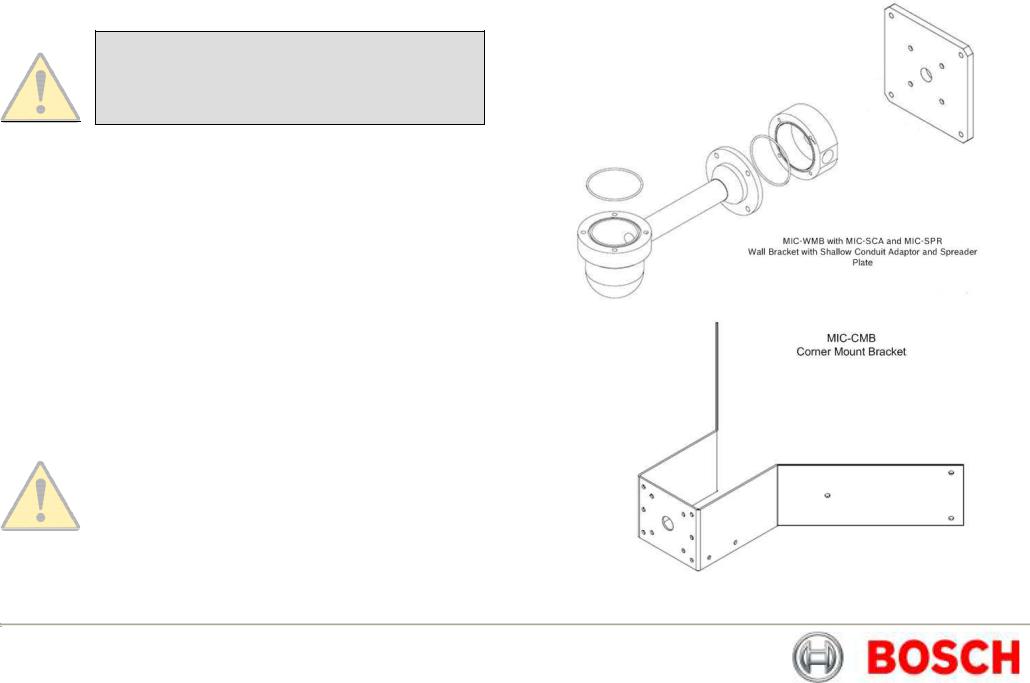
For mounting directly onto buildings Bosch Security Systems manufacture a range of brackets suitable for all typical building installations for upright (90°) or Inverted camera positions, examples are shown below.
MIC-CMB |
- |
Corner Mount Bracket |
MIC-WMB |
- |
Wall Mount Bracket |
MIC-SCA |
- |
Shallow Conduit Adaptor |
MIC-DCA |
- |
Deep Conduit Adaptor (Included) |
MIC-PMB |
- |
Pole Mount Bracket |
|
|
|
|
|
CAUTION: For additional protection in hazardous area |
|
|
installations suitable flexible conduit can be used externally for |
|
|
the composite cable run to connect the power supply to the |
|
|
Exd Cable Gland (Not supplied) in the MIC440 Deep Conduit |
|
|
Adaptor |
|
|
|
Bosch Security Systems |
Issue 6 |
MIC440 Explosion Protected CCTV Camera System| Installation and Operation Manual |
EN | 10 |
CHAPTER 2 Hardware Installation
CAUTION: Ensure all local safety codes are observed when installing this product; ensure a strong safety chain is used to secure the MIC440 camera to prevent any danger of dropping the product during installation.
This product is designed for use with flammable gases and vapors covered by apparatus groups IIA, IIB and IIC and with temperature classes T1 to T6.
The product is certified for use within the ambient temperature range of -20C to +60º C and must not be used outside this range.
This product must only be installed by suitably trained personnel in accordance with the relevant code of practice (e.g. EN6007914:1997). These instructions are intended for their sole use.
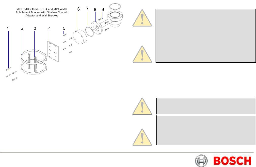
Key to MIC-PMB drawing
1.Securing bolts for MIC-SCA
2.90mm stainless steel pole banding
3.Pole mount bracket blocks
4.Pole mount bracket plate
5.Pole mount block securing securing bolts
6.Shallow conduit adaptor
7.“O”-ring
8.Wall mount bracket
9.Wall mount bracket securing bolts
The MIC440 uses a composite cable to carry all power & telemetry between the camera head and the MIC power supply unit this cable can be a maximum of 25m long, for installations which require the camera head to be more than 25m from the power supply then it is recommended that a 2m cable be connected to an Exd rated junction box from which telemetry; video and power can be broken out into separate cables with appropriate wiring to extend the distance to suit.
CAUTION: Any junction box or enclosure used for mounting the power supply or separating cable cores must be Exd rated to the appropriate rating for the installation.
CAUTION: If the camera is mounted ball down it is essential that the connector and base area of the camera are completely sealed from water ingress.
CAUTION: Any water getting into the connector is liable to cause corrosion to the connector pins leading to unreliable operation of the camera unit.
Bosch Security Systems |
Issue 6 |
MIC440 Explosion Protected CCTV Camera System| Installation and Operation Manual |
EN | 11 |
Pre installation Preparation in the Workshop
The unit is NOT supplied with a external Exd cable gland. A suitable sized Exd barrier gland to match the composite cable diameter is required. For the Bosch composite cable (8mm); use a Hawke cable gland type 501/421 Size 0.
The composite cable is required to connect the MIC440 to its power supply it consists of two pairs (24AWG) plus 4 cores of (22 AWG), 2 cores of (24 AWG) and one coax core for the video signal to a maximum distance of 25m as per Table B.
CAUTION: It is recommended that the cable and connector should be made up, connected to the unit and sealed with the Exd barrier gland in a workshop before taking the unit for mounting on site.
All connections to the unit are made via the single 12 way connector mounted on the base of the camera unit and accessible through the base conduit adaptor.
Cable Gland and Cable Mounting instructions
1.Remove the 4 x M8 Hexagon bolts holding the base conduit adaptor to the MIC440 unit and remove the base conduit adaptor.
2.Fit the composite cable through the Exd barrier gland.
3.Fit the composite cable through the 20mm threaded gland hole in the base conduit adaptor and allow approx 100mm of free cable on the inside to connect to the 12 way cable connector.
4.Screw the Exd barrier gland into the base conduit adaptor maintaining approx 100mm of cable on the inside of the adaptor to enable the cable connector to be freely inserted into the MIC unit base connector.
5.Connect the 12 way cable connector into the matching connector in the base of the MIC unit.
6.Make sure the connector is fitted home properly in the camera integral plug (requires approx. two and a half turns of the socket threaded ring to fasten the two halves of the connectors together properly).
7.Fit the base conduit adaptor back to the MIC440 unit and fasten using the 4 x M8 hexagon bolts.
8.Ensure that there are no trapped cables.
9.Ensure there is some slack cable in the base conduit adaptor then tighten up and seal the Exd barrier gland as per the instructions included with the gland.
10.The unit with the cable tail is now ready for on site installation
Camera Installation Instructions
1.Locate the mounting position of the camera so that it cannot be interfered with either intentionally or accidentally.
2.Ensure the mounting surface is capable of supporting the combined weight of the camera and mounting hardware under all expected conditions of load, vibration and temperature.
3.Fit the mounting brackets (if used) securely, observing all appropriate safety precautions & local building regulations.
4.Earth the camera using one of the securing bolts. Only earth the camera at a single point to prevent earth loops & hum bars.
5.M8 x20mm Stainless steel nuts, bolts and washers should be used to secure the camera’s base conduit adaptor to the mounting point.
6.Secure all cabling & conduit.
Bosch Security Systems |
Issue 6 |

MIC440 Explosion Protected CCTV Camera System| Installation and Operation Manual |
|
|
|
|
|
|
EN | 12 |
||
|
L |
|
Power input |
|
Low volt AC or DC power |
|
22 AWG core |
|
|
Electrical Connections to the MIC440 |
|
|
1 |
|
|
input 15 Volts AC or DC |
|
- Red |
|
|
|
|
|
|
|
|
|
||
The MIC440 base connector pin allocations are as follows: |
M |
|
Power input |
|
Low volt AC or DC power |
|
22 AWG core |
|
|
|
|
2 |
|
|
input 15 Volts AC or DC |
|
- Green |
|
|
|
|
|
|
|
|
|
|
|
|
Table B – MIC Connector Pin Table
Connector Pin |
Signal |
|
Name |
A |
|
Video |
|
|
Output |
|
|
|
B |
|
Video |
|
|
Return |
|
|
|
C |
|
Tamper |
|
|
Switch |
|
|
|
Description
Video Signal output to control room
Video Signal Ref output to control room
Connection C to D will provide an alarm to the control
Cable Wire
Type/Colour
Coax core
Coax screen
24 AWG core - Black
D |
|
Tamper |
|
room via telemetry |
|
24 AWG core |
|
|
Switch |
|
|
|
- Brown |
|
|
return |
|
|
|
|
|
|
|
|
|
|
|
E |
|
Washer |
|
TTL ref output can be used |
|
22 AWG core |
|
|
drive return |
|
to drive external relay for |
|
- Grey |
|
|
|
|
wash operation option |
|
|
|
|
|
|
|
|
|
F |
|
Washer |
|
TTL output can be used to |
|
22 AWG core |
|
|
drive |
|
drive external relay for |
|
- Orange |
|
|
|
|
wash operation option |
|
|
|
|
|
|
|
|
|
G |
|
Full Duplex |
|
Telemetry Output RS 485 |
|
Pair 1 - Blue |
|
|
Tx A |
|
|
|
|
|
|
|
|
|
|
|
H |
|
Full Duplex |
|
Telemetry Output.RS485 |
|
Pair 1 - Violet |
|
|
Tx B |
|
|
|
|
|
|
|
|
|
|
|
J |
|
Full Duplex |
|
Telemetry I/O to RS485 |
|
Pair 2 - |
|
|
Rx A |
|
|
|
Yellow |
|
|
Half Duplex |
|
|
|
|
|
|
Tx/Rx A |
|
|
|
|
|
|
|
|
|
|
|
K |
|
Full Duplex |
|
Telemetry I/O to RS485 |
|
Pair 2 - White |
|
|
Rx B |
|
|
|
|
|
|
Half Duplex |
|
|
|
|
|
|
Tx B |
|
|
|
|
|
|
|
|
|
|
|
Video output signal conforms to CCIR PAL 1V Composite format. (NTSC format is available on request).
Telemetry signals all conform to the RS485 / RS422 standard.
The unit continuously monitors incoming telemetry whether in full or half duplex mode.
In full duplex mode, the Tx pins are tri-state except during transmission times. This may cause problems when interfacing to some Fibre Optical converter units. Check out the Commissioning notes for ways of overcoming these problems.
In 2 wire Half Duplex mode (RS485), the Rx Pins are used to transmit data to the MIC440 unit.
The washer connections can be used to operate a relay in the power supply unit, which in turn can activate a pump.
Bosch Security Systems |
Issue 6 |

MIC440 Explosion Protected CCTV Camera System| Installation and Operation Manual |
EN | 13 |
|
Earthing of the MIC440 Camera |
Maintenance |
|
1.The camera module & housing are electrically isolated so the housing should be safety earthed regardless. The safety earth should be a bonding connection to the cameras outside case for example one of the securing bolts.
2.The camera should be earthed at one point only to prevent earth loops & thus hum bars showing on the control room monitor.
3.If the system is copper throughout & the camera pictures are fed back to the control room coaxial copper cable, then the camera should be earthed at the video termination point in the control room & nowhere else. In this case the PCB “Earth Link” should be broken.
4.If the video is transmitted back to the control room via some non electrical connecting medium, e.g. fibre optic, radio or microwave link, then the camera should be earthed at the transmitter point in the psu. The PSU “Earth Link” may be used for this purpose.
5.If dual earthing is unavoidable then a video isolation transformer should be fitted between the two earths.
Lightning Protection
If the camera is fitted in a highly exposed place then consideration should be given to lightning protection. A good earth bonding connection to the case itself will provide protection against damage from secondary strikes.
Where there is a risk of a primary strike hitting the camera housing directly, it is recommended that a separate lightning conductor be fitted within 0.5m of the camera and at least 1.5m higher than the camera.
The construction of the housing itself is very capable of coping with secondary strikes and no damage to the internal electronics or camera should result if correct lightning protection is applied.
The unit contains no maintainable parts and in the event of failure should be removed from site for repair.
Maintenance and repair of this equipment shall only be carried out by suitably trained personnel in accordance with the applicable code of practice (e.g. EN60097-19)
To maintain the validity of the certification only components supplied by Bosch Security Systems shall be used.
On Site Inspection
It is recommended that the equipment be inspected on site every six months to check mounting bolts for tightness, security and any signs of physical damage. Inspection of this equipment shall only be carried out by suitably trained personnel in accordance with the applicable code of practice (e.g. EN60097-17)
Bosch Security Systems |
Issue 6 |
MIC440 Explosion Protected CCTV Camera System| Installation and Operation Manual |
EN | 14 |
CHAPTER 3 Power Supply Installation & Setup
The Power Supply Units provide all the support functions for connecting the MIC440 cameras to third party equipment, they comprise of the following products:
MIC-12PSU, MIC-240PSU, MIC-24PSU and MIC-115 PSU
The power supply provides power for a single MIC440 camera unit from a 12v DC source (MIC-12PSU), a 240v AC source (MIC-240PSU), a 24v AC source (MIC24PSU) or a 115v AC source (MIC-115PSU). The transformer fitted to these designs is a thermally protected and automatically cuts out if the transformer core temperature exceeds 40 Degrees C. On cooling the transformer will become operational again.
In addition the unit provides all the terminations required to connect a MIC440 camera to third party equipment.
A second independent 12v (600mA) power supply is also included to drive any internally fitted optional interface cards.
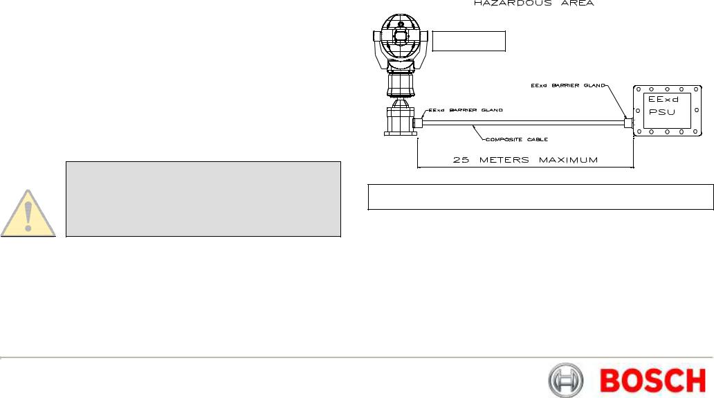
A maximum cable length of 25m is permitted as shown overleaf in Fig A, if the PSU can be located in a Non-hazardous area near to the camera installation then an Exd enclosure for the PSU may not be required as shown in Figure B on page 15.
MIC440
Hazardous Area Power Supply Installation Instructions
CAUTION: The PSU enclosures are not Exd rated and must be replaced with a certified enclosure if installed within a
hazardous area. Figure A – Installation using Exd junction box
This product must only be installed by suitably trained personnel in accordance with the relevant code of practice (e.g. EN60079-14:1997).
Installation of the PSU within a hazardous area must have the standard PSU enclosure replaced with an appropriate certified enclosure and four (4) Exd cable glands (NOT Supplied), the power supply PCB is usually re-housed, by a third party company, within an Exd enclosure which is then factory certified and shipped to site. Follow all manufacturer’s instructions when installing a third party Exd enclosure, examples are shown on Page 15.
Bosch Security Systems |
Issue 6 |

MIC440 Explosion Protected CCTV Camera System| Installation and Operation Manual |
EN | 15 |
Bosch Security Systems |
Issue 6 |
MIC440 Explosion Protected CCTV Camera System| Installation and Operation Manual |
EN | 16 |
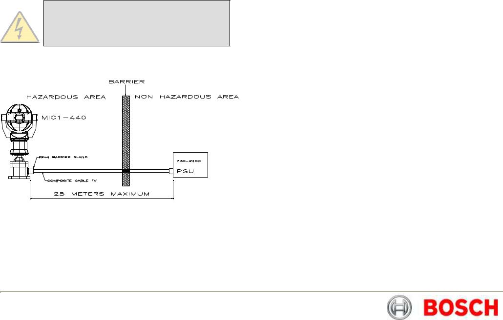
Non Hazardous Area Power Supply Installation Instructions
WARNING: Electrical Danger: Ensure all power is disconnected before opening or working upon any Power Supply Unit.
Installation must be carried out by suitably qualified persons & all local safety regulations should be followed.
Figure B – Installation of the PSU in a Non-Hazardous area
Installation of the MIC-PSU
To install the MIC-PSU in a Non-Hazardous area please do the following.
1.Locate the mounting position of the MIC-PSU outside the hazardous area so that it cannot be interfered with either intentionally or accidentally, a lockable cabinet is recommended.
2.Securely fix the MIC-PSU using M4 stainless steel screws & washers; ensure the cable glands have sufficient room to allow for the cables to enter.
3.Feed all cabling through the appropriate sized gland holes.
4.Connect the composite cable to HD3 following the colour coding as shown in the Table D & printed on the PCB.
5.If a tamper switch relay is to be used, connect this at HD2.
6.Connect the Coaxial video cable to the CN1 header.
7.CN2 is for additional add on cards such as alarm inputs, video processors, Bi-phase cards etc.
8.Telemetry connections are provided by headers HD3, HD4 and HD5 which respectively enable crimp or screw terminations for connecting the MIC440 to the control room as per Table E.
9.Connect the power to HD1 carefully observing the polarity and voltage as per Table C.
10.When wiring is complete, apply power & check the all four (4) LED’s are lit.
11.Following Installation when power is applied the following LEDs will light to indicate:-
LED1 – 15vAC power on to camera LED2 – 15vAC power on to camera
LED4 – Power on for optional heater/speaker (Not MIC440) LED5 – Power on for optional heater/speaker (Not MIC440)
12.Re-attach the enclosure lid & screw down until tight.
13.For installation of the MIC-WKT-KIT, MIC-ALM or MIC-BP-4 Bi-phase card please refer to their respective manuals.
Bosch Security Systems |
Issue 6 |
MIC440 Explosion Protected CCTV Camera System| Installation and Operation Manual |
EN | 17 |
Connecting the MIC-24PSU, MIC-240PSU or MIC-115PSU
Once installed on site please connect the composite cable from the MIC440 to the MIC-PSU as per the following instructions.
WARNING: Electrical Danger: Ensure all power is disconnected before opening or working upon any Power Supply Unit. Installation must be carried out by suitably qualified persons & all local safety regulations should be followed.
The Power Supply Unit comprises of the following:
1)A weather resistant (IP55) plastic box fitted with four cable glands.
2)A power supply for the MIC440 camera.
3)A second power supply for driving various interface cards mounted internally to the power supply box. e.g. washer drive card, alarm interface card.
4)Provision for a signal interface card, to connect telemetry to third party equipment.
5)Screw termination of all cable into and out of the box.
6)Correct video termination for the camera coaxial cable.
7)Earth isolation and termination within the unit to correctly control Video earthing and thus prevent Earth loop.
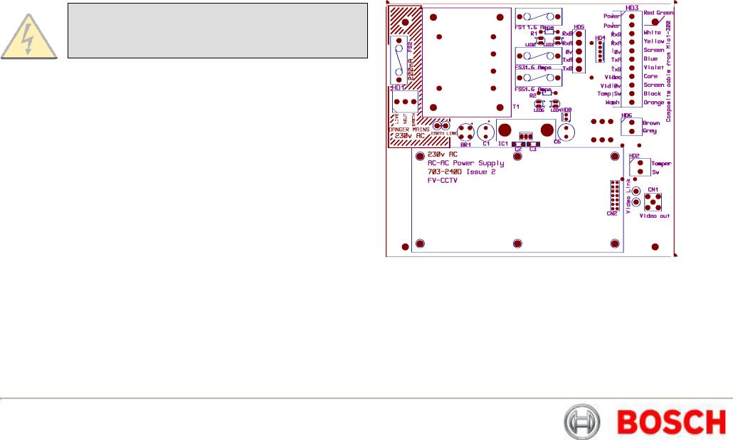
Power Supply Layout and Connections
The Power supply PCB has the following connections as shown overleaf on Figure C:-
HD1 – Power Input Connector (screw terminal) HD2 - Tamper Switch header (screw terminal)
HD3 - Composite cable header (Connections to camera head, screw terminal) HD4 - Telemetry header (Molex Connection)
HD5 - Telemetry header (screw terminal) HD6 - Washer pump header (screw terminal)
HD8 - Keyboard power connector (demo purposes only, not normally fitted) CN1 - Video out connection header (BNC)
CN2 - Add on card header (plug in)
Dimensions
Power supply enclosure:-225mm (W) x 70mm (H) x 195mm (D)
Figure C - MIC24PSU/MIC-240PSU/MIC-115PSU Layout
PCB Earth Link
The PCB has one link option next to HD1 to allow the power supply to be set up for different earthing schemes: The Earth Link should be broken if there is a separate connection between video screen and earth. Usually occurs on copper connected systems where all the copper video coaxes are taken back to the control room to be connected to a central earth point. If fibre optics or other indirect connections are used to get data and video to and from the control room then the earth link should be left intact provided it is the only camera end earth reference point.
Bosch Security Systems |
Issue 6 |

MIC440 Explosion Protected CCTV Camera System| Installation and Operation Manual |
EN | 18 |
Table C – Power Connection to Header HD1
|
|
|
|
|
|
Live |
|
HD1-1 |
|
|
|
|
|
|
|
Neutral |
|
HD1-2 |
|
|
|
|
|
|
|
Earth |
|
HD1-3 |
|
|
|
|
|
|
Table D - Composite cable to Power Supply HD-3 Connection Table
|
|
|
|
|
|
|
|
|
|
Composite |
|
Function |
|
Terminal Box |
|
Terminal |
|
|
Cable Wire |
|
|
|
Connector |
|
Box ID |
|
|
Colour |
|
|
|
|
|
Marking |
|
|
|
|
|
|
|
|
|
|
|
Red |
|
AC supply |
|
HD3-1 |
|
Power |
|
|
|
|
|
|
|
|
|
|
|
Green |
|
AC supply rtn. |
|
HD3-2 |
|
Power |
|
|
|
|
|
|
|
|
|
|
|
|
|
|
|
|
|
|
|
|
White |
|
Rx + |
|
HD3-3 |
|
RxB |
|
|
|
|
|
|
|
|
|
|
|
|
|
|
|
|
|
|
|
|
Yellow |
|
Rx - |
|
HD3-4 |
|
RxA |
|
|
|
|
|
|
|
|
|
|
|
Drain Wire |
|
Gnd |
|
HD3-5 |
|
GND |
|
|
|
|
|
|
|
|
|
|
|
Blue |
|
Tx - |
|
HD3-6 |
|
TxA |
|
|
|
|
|
|
|
|
|
|
|
Violet |
|
Tx + |
|
HD3-7 |
|
TxB |
|
|
|
|
|
|
|
|
|
|
|
Coax Core |
|
Video |
|
HD3-8 |
|
Video |
|
|
|
|
|
|
|
|
|
|
|
Coax Screen |
|
Video Return |
|
HD3-9 |
|
Vid 0v |
|
|
|
|
|
|
|
|
|
|
|
Black |
|
Tamper Switch |
|
HD3-10 |
|
Tamp Sw |
|
|
(Optional) |
|
|
|
|
|
|
|
|
|
|
|
|
|
|
|
|
|
Orange |
|
Wash drive |
|
HD3-11 |
|
Wash |
|
|
(Optional) |
|
|
|
|
|
|
|
|
|
|
|
|
|
|
|
|
Table E - Telemetry Connections to HD3, HD4 and HD5
Telemetry |
HD3 |
HD4 |
HD5 |
Signal Name |
|
|
|
RXB or Rx + |
Pin 3 |
Pin 1 |
Pin 1 |
|
RXA or Rx - |
|
Pin 4 |
|
Pin 2 |
|
Pin 2 |
|
|
|
|
|
|
|
|
|
|
|
|
|
|
|
|
|
|
|
|
GND |
|
Pin 5 |
|
Pin 3 |
|
Pin 3 |
|
|
|
|
|
|
|
|
|
|
|
TXA or Tx - |
|
Pin 6 |
|
Pin 4 |
|
Pin 4 |
|
|
|
|
|
|
|
|
|
|
|
|
|
|
|
|
|
|
|
|
TXB or Tx + |
|
Pin 7 |
|
Pin 5 |
|
Pin 5 |
|
|
|
|
|
|
|
|
|
|
|
|
|
|
|
|
|
|
|
Fuse ratings
The power supply houses 4 off 20mm fuses in fuse holders. The ratings for these fuses if fixed on the low voltage secondary side but changes with input voltage on the high voltage primary side.
The following table shows the fuse values fitted for the different supplies for operating the power supply:
Note FS 4 does not exist
Table F – Fuse Ratings for MIC-240PSU, MIC-24PSU and MIC-115PSU
Fuse ident |
FS 1
FS 2
FS 3
FS 5
|
|
|
|
|
|
Fuse function. |
|
Rating for 240v |
|
Rating for 115v |
|
|
|
primary |
|
primary |
|
|
|
|
|
|
|
MIC400 protection |
|
1.6A glass Anti |
|
1.6A glass Anti |
|
|
|
surge (T) |
|
surge (T) |
|
|
|
|
|
|
|
|
|
|
|
|
|
Primary protection. |
|
800mA ceramic |
|
800mA ceramic |
|
|
|
quick blow |
|
quick blow |
|
|
|
|
|
|
|
Heater protection 1 |
|
1.6A glass Anti |
|
1.6A glass Anti |
|
|
|
surge (T) |
|
surge (T) |
|
Heater protection 2 |
|
1.6A glass Anti |
|
1.6A glass Anti |
|
|
|
surge (T) |
|
surge (T) |
|
Bosch Security Systems |
Issue 6 |
MIC440 Explosion Protected CCTV Camera System| Installation and Operation Manual |
EN | 19 |
MIC-12PSU Power Supply Unit
The power supply provides power for a single MIC440 camera unit from a 9v DC to 29v DC source for installations using low voltage systems.
Dimensions
Power supply enclosure – 225mm (W) x 70mm (H) x 195mm (D)
This is connected as per the MIC-240PSU as shown previously with the exception of the following changes:-
WARNING: Electrical Danger: Ensure all power is disconnected before opening or working upon any Power Supply Unit. Installation must be carried out by suitably qualified persons & all local safety regulations should be followed.
CAUTION: It is extremely important to observe the correct polarity, failure to do so will result in the destruction of the DC-DC power supply.
CAUTION: This power supply was designed for negative earthed systems only it is not suitable for use with positive earth systems.
This should be fed in to connection HD1 nominally marked as mains input, connections should be as follows:-
Table G – Power Input wiring connections for MIC-12PSU
|
|
|
|
|
|
Positive |
|
HD1-1 |
|
|
|
|
|
|
|
Negative |
|
HD1-2 |
|
|
|
|
|
|
|
Earth and Negative |
|
HD1-3 |
|
|
|
|
|
|
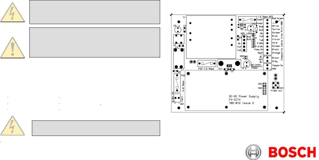
Power Supply Layout and Connections
HD1 – Power Input Connector (screw terminal)
HD2 - Keyboard power connector (demo purposes only, not normally fitted) HD3 - Composite cable header (Connections to camera head, screw terminal) HD4 - Telemetry header (Molex Connection)
HD5 - Telemetry header (Screw terminal) HD6 - Tamper Switch header (Screw terminal)
HD7 – Washer Pump Drive header (Screw terminal) CN1 - Video out connection header (BNC)
CN2 - Add on card header (plug in)
Figure C – MIC-12PSU Layout
WARNING: The rating of fuse FS2 should be changed to a 2A quickblow as opposed to the rating shown on the PCB.
For 12V installations the composite cable wiring is identical to that shown earlier in this manual on Table D.
|
|
|
|
|
|
|
|
Bosch Security Systems |
Issue 6 |
||

MIC440 Explosion Protected CCTV Camera System| Installation and Operation Manual |
|
EN | 20 |
|
Optional Cards and Kits for MIC440 Cameras |
CHAPTER 4 |
Configuring the MIC440 Camera |
|
The MIC440 has several optional cards and kits as described earlier.
Please refer to the respective manuals for details on their installation and operation.
MIC-WKT
MIC-ALM
Connecting the MIC440 to the PC
CAUTION: This procedure must be carried out in a non hazardous area only.
The MIC can be connected to a PC’s serial port via a RS232/RS422 adaptor unit; this will generally be assigned to Comm Port 1.
MIC-BP4 |
Suitable serial port adaptor units are the Greenwich RS232/RS422 adaptor unit |
|
(Farnell 778-758, RS No: 201-758), the KK systems K2-ADE RS232 to RS485/422 |
|
adaptor or the MIC-USB485CVTR (485 to USB Converter) for PC’s without a serial |
|
port. |
Connecting the Greenwich Adaptor
To connect the Greenwich serial adaptor to the PC you will also need a 9 pin D female to 25 pin D male RS232 compatible adaptor cable. A suitable cable is Farnell 960-573 or RS Part No: 202-644. The adaptor should be set to DCE mode and the power supply connected.
Connections from the Greenwich adaptor to the power supply are shown below
Table H – Connecting the Greenwich Adaptor
Adaptor Connections
F 778-758.
DATA OUT 6-3+
DATA OUT 5-4-
SCREEN
DATA IN 4-5-
DATA IN 3-6+
HD4
Connection and wire colour.
RXB White
RXA Yellow
0v
TXA Blue
TXB Violet
Bosch Security Systems |
Issue 6 |
MIC440 Explosion Protected CCTV Camera System| Installation and Operation Manual |
EN | 21 |
The connections can be tested by selecting the DETECT button in Camset and checking to see if the window below this button displays the address and software version No of the camera being tested.
Should a problem be encountered then connect the MIC440 screen wire (0v) to the pc chassis with a separate piece of wire to ensure 0v continuity
Connecting the KK systems K2-ADE RS232 to RS485/422 Adaptor
This unit is self powered and can be plugged directly into the PC serial port. RS485 two wire mode.
Connections and Dip switches settings for 2-wire mode should be made as follows:-
Table I – DIP Switch Settings for K2-ADE 2 wire mode
|
|
|
|
|
|
DIP Switch |
|
Setting |
|
|
|
|
|
|
|
|
|
|
|
|
Sw 1 |
|
OFF |
|
|
|
|
|
|
|
Sw 2 |
|
OFF |
|
|
|
|
|
|
|
Sw 3 |
|
OFF |
|
|
|
|
|
|
|
Sw 4 |
|
ON |
|
|
|
|
|
|
|
Sw 5 |
|
OFF |
|
|
|
|
|
|
|
Sw 6 |
|
ON |
|
|
|
|
|
|
Table J – K2-ADE Adaptor connections
Adaptor Connections
K2-ADE
Pin 3
Pin 9
Pin 5
Not required
Not required
HD4
Connection.
RXB White
RXA Yellow
0v
TXA Blue
TXB Violet
With all the above set up, when Camset is running and the serial port selected, set the Camera Interface Controls to the following:-
Table K – Camera interface control settings
|
|
|
|
|
|
|
|
|
|
|
|
|
|
|
Camset Tabs |
|
|
|
2 Wire RS485 |
|
|
|
4 Wire RS422 |
|
|
|
|
|
|
|
|
|
||||||
|
Comms 1 |
|
Selected |
|
Selected |
|
||||||
|
|
|
|
|
|
|
||||||
|
|
|
|
|
|
|
||||||
|
Interface |
|
2 Wire |
|
4 Wire |
|
||||||
|
|
|
|
|
|
|
|
|||||
|
RTS |
|
Off |
|
|
On |
|
|||||
|
|
|
|
|
|
|
|
|
||||
|
Baud |
|
9600 |
|
|
9600 |
|
|
||||
|
|
|
|
|
|
|
|
|
|
|
|
|
|
|
|
|
|
|
|
|
|
|
|
|
|
If a notebook PC is used, which sometimes lacks a serial port, then a RS485 to USB converter such as the MIC-USB485CVTR can be used instead, this would typically be mapped to Comms port 3 or 4.
Bosch Security Systems |
Issue 6 |
MIC440 Explosion Protected CCTV Camera System| Installation and Operation Manual |
EN | 22 |
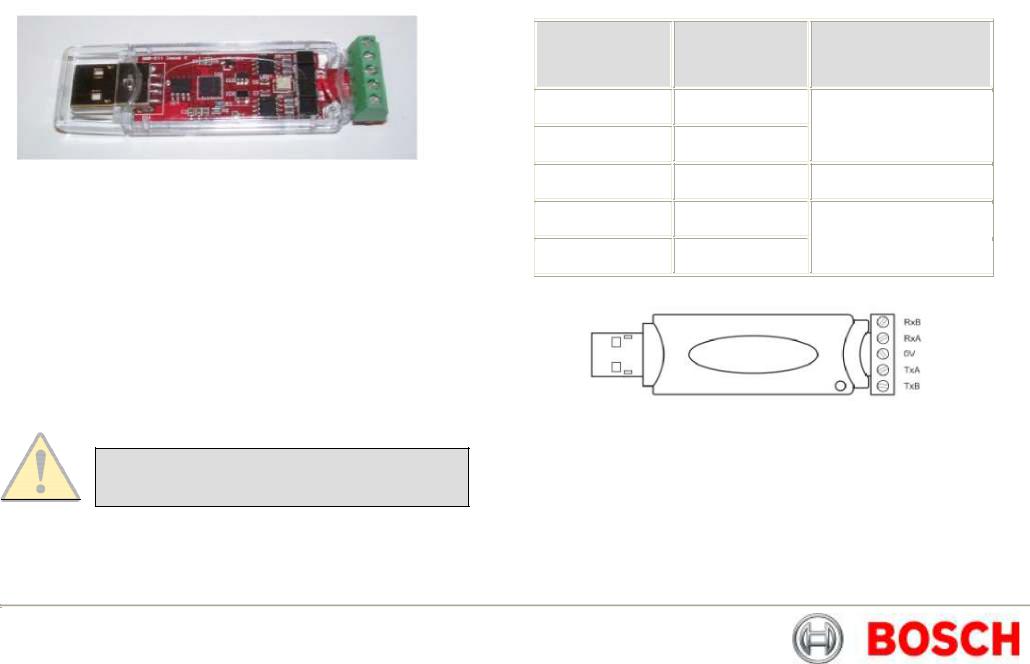
Connecting the MIC-USB485CVTR, USB to RS485 Converter
The MIC-USB485CVTR is a USB to RS485 signal converter that allows PCs without a serial port to connect directly to the MIC440 camera via the telemetry connection (HD4) in the power supply, the MIC-USB485CVTR can also be used to connect a PC to any other RS485 device.
The MIC-USB485CVTR has been designed to work with all functions in Universal Camset and to be backwards compatible with legacy version of Camset although full compatibility is not guaranteed.
The MIC-USB485CVTR should be connected to the telemetry header (HD4) of the MIC440 power supply with Standard Twisted Pair cable such as Belden 8760.
The table overleaf shows how the screw terminal connections on the MICUSB485CVTR connect to the MIC power supply depending upon the protocol and selected communication mode you may only need a 2 wire configuration.
CAUTION: Should be taken to avoid earth loops when connecting 0v from the converter to GND terminal in the MIC power supply
Table L – MIC-USB485CVTR Connection Table and Diagram
Converter Output
RxB / Rx -
RxA / Rx +
GND / 0V
TxA / Tx -
TxB / Tx +
MIC Power Supply
Telemetry Header
(HD4 or HD5)
TxB
TxA
GND
RxA
RxB
Communication Mode
Full Duplex (4-wire only)
Shield (always)
Simplex
Half Duplex (2-wire)
Full Duplex (4-wire)
Bosch Security Systems |
Issue 6 |
MIC440 Explosion Protected CCTV Camera System| Installation and Operation Manual |
EN | 23 |
MIC-USB485CVTR and Universal Camset Software Installation
Universal Camset comes with WHQL certified drivers for the MIC-USB485CVTR that must be installed prior to connecting the converter to the PC.
To install the drivers please do the following:-
Commissioning the MIC440 using Universal Camset
Universal Camset is a Windows PC based configuration software from BOSCH Security Systems; it is issued free on the CD that comes with each MIC camera. Universal Camset supersedes all previous versions of Camsets used.
1.Locate the USB DRIVERS.EXE in the Universal Camset Folder, double click to begin and follow the on screen instructions to install; these are the required drivers for using the MIC-USB485CTR.
2.Locate the CAMSET INSTALLER.MSI and then double click to begin, follow the on screen instructions to install.
3.Once installed a Universal Camset Icon will appear on your PC Desktop.
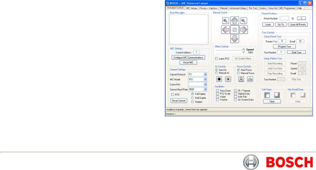
4.When opened the Universal Camset will display the Standard Controls Tab as shown overleaf.
Providing the USB drivers have been installed successfully, you can then plug the MIC-USB485CVTR into a PC via the USB port. If your converter is being plugged in for the first time your system should recognise the device and inform you that the hardware has been installed successfully.
The MIC-USB485CVTR should appear in the Comm Port selection list as USB and as a virtual Comm Port, e.g “comm2” (for legacy support). Universal Camset has been optimised to work with this converter in USB mode; therefore users should select “USB” for maximum functionality and reliability.
The MIC-USB485CVTR has a status LED indicating its current state, by sending a manual command e.g. Left or Right, you should see the LED flash. Transmitted data from the converter is indicated by a red flashing LED flash and upon receiving data a green LED will flash.
Standard Controls
Universal Camset opens on the Standard Controls tab as shown above; the highlighted area contains the Boot messaging, MIC settings and Camset Settings controls.
Bosch Security Systems |
Issue 6 |
MIC440 Explosion Protected CCTV Camera System| Installation and Operation Manual |
EN | 24 |
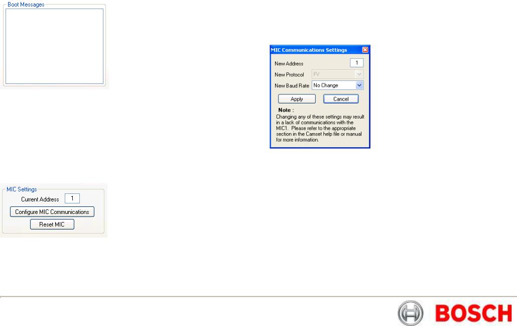
Boot Messages
The large square text box in this area will display boot messages coming from the MIC. One of the first lines contains the MIC address which is decoded and entered into the Address line. The rest of the lines indicate the MIC model number, control card serial number, MIC Software etc.
At the same time, a boot message is displayed on the video indicating similar information, which may be helpful if return comms should fail or be incorrectly connected.
MIC Settings
Current Address
This box indicates the address to which commands are sent from Camset. This therefore needs to match the address of the MIC that needs to be controlled.
When the MIC is booted the first line of the messages it sends is the address, which is read and put into this box automatically.
Configure MIC Communications
This button opens up a new window which provides the options to reconfigure the MIC communications settings. These options will depend on the MIC model connected.
In order for any of these modifications to work, Camset must have full communications with the MIC. Ensure this by performing a simple manual control test (Up, Down, etc). To store the new settings press Apply once the modifications have been made or alternatively press Cancel to discard any changes.
New Address
This input box defines the new address the MIC should change to once Apply has been clicked. The value will also be copied over into Current Address on the main form to provide continual control.
New Protocol
The drop down list here provides a full list of the protocols available in Camset. Control depends upon selecting the correct protocol in the drop down list to match the protocol that is loaded onto the MIC400; if the incorrect protocol is selected in Camset the MIC may not respond. To regain control should this happen, reset the Camset Protocol back to what the MIC originally was.
Bosch Security Systems |
Issue 6 |
MIC440 Explosion Protected CCTV Camera System| Installation and Operation Manual |
EN | 25 |
New Baud Rate
This drop down list will provide the valid baud rates for the chosen protocol. The baud rate options reflect the protocol as set on the main form for Camset itself. In FV protocol the option is a toggle which simply switches the MIC between 4800 and 9600. If control is not present after the window is closed, try changing the Camset Baud Rate.
Reset MIC
This sends out a command to reboot the software. This is not a hardware reboot; the only way to do that is to remove the power supply to the MIC.
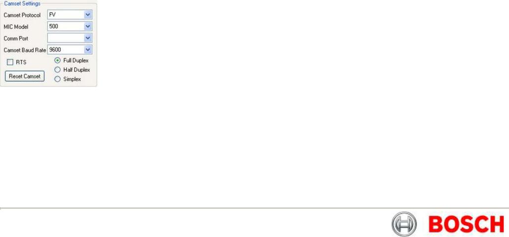
Camset Settings
The Camset Settings section as shown above control the Protocol, MIC model, Baud Rate and Comm Port used; select the appropriate parameters for your MIC440 from the dropdown menus.
Some functions in Universal Camset may not be supported by particular protocols; any incompatible functions will be greyed out if it is not supported in a given protocol.
The communication settings will be set to the default for the chosen protocol, indicating this on the Camset Baud Rate drop down list.
Reset Camset
This re-initialises all of the controls for the software to the state it would be on boot.
MIC Model
This provides a list of all the available MIC Models. This should be set to the type of camera being controlled as Camset is then set up accordingly to provide more or less options dependant upon the combination of this setting with the Camset Protocol above.
Comm Port
This provides a list of the available Comm Ports detected by the software on the PC. If a comm port is in use when it is selected the user will be prompted with an error, and should either select another port or close the application currently using it. If the MIC-USB485CTR, USB to RS485 convertor is being used, when plugged in this will show on the Comm Port drop down menu as USB, simply select to use. The final option is close which will close any open communications port meaning that other applications can then use the port for other purposes.
Camset Baud Rate
This displays the current Baud Rate at which outgoing messages are sent, and the other options available for the given protocol above. Changing this without first changing the MIC baud rate will cause a loss of communications.
RTS
This defines the state of the RTS line on the serial port which can be used power in line RS232 to 485 adapters.
Comms Mode
There are 3 available options for comms modes:
Full Duplex: Full 2 way 4 wire communications connection. Messages are transmitted and received on separate comms pairs.
Half Duplex: 2 way, 2 wire communications connection. Messages are transmitted and received on the same pair of wires. The 485 drivers deal wih the switching of the line directions automatically.
Simplex: 1 way 2 wire communications connection. Messages are only transmitted to the camera. This will work for most manual controls, but anything that requires a response, such as Pot Test, Exact Positioning, Programming etc will fail.
Bosch Security Systems |
Issue 6 |
MIC440 Explosion Protected CCTV Camera System| Installation and Operation Manual |
EN | 26 |
|
Manual Control |
Iris Controls |
|
Pan, Tilt and Zoom Controls
The Up, Down, Left and Right buttons send commands to the MIC to move in the selected direction at the speed indicated by the Speed Slider.
Zoom In  and Zoom Out
  control the zoom position of the camera lens at a fixed rate.
Latch PTZ: This tickbox will Latch the PTZ controls for continuous tilt or rotation as required.
Auto Iris lets the MIC automatically adjust to changing light levels, where Manual
Iris gives the user control with Open  and Close
  buttons.
Focus Controls
Auto Focus lets the MIC automatically focus on a changing scene, Manual Focus
gives the user control with Near  and Far
  buttons.
Bosch Security Systems |
Issue 6 |

MIC440 Explosion Protected CCTV Camera System| Installation and Operation Manual |
EN | 27 |
|
Auxiliaries |
Preset Positions |
|
Slow Zoom: Reduces the speed at which the MIC zooms.
PTZ Scale: Scales the MIC speed dependant on zoom position.
Wiper: Turns on or off the MIC wiper if fitted.
Washer: Activates the washer relay on the MIC-WKT card or the MIC-ALM card if fitted in the PSU. This also moves the MIC to the stored WashWipe position and turns on the wiper. Once de-activated the MIC will return to its original position and turn off the wiper.
IR / Thermal: Dependant on the MIC this will do one of 3 things, for a Non-IR Standard MIC the IR cut filter will come in and the image will go black and white. For a twin IR MIC, the cut filter will come in and the lamps will turn on.
Note: If the lamps do not turn on, ensure the power supply is an IR version and that Auto Alarm and Multi Alarms in the MIC Setup tab are both turned on.
For a MIC412, the video output will switch from the Sony module to the thermal module; the controls on the Thermal tab will also now function.
Digital Zoom: This will enable the MIC to continue into the digital zoom once the optical limit has been reached. This also needs to have Digital Zoom Enabled under the MIC Setup tab.
Auto Pan: This will start the MIC panning between left and right defined limits.
On Screen Data: This activates the Sony modules on screen icons.
Preset positions are locations stored by the MIC in Pan, Tilt and Zoom, Focus etc, which can be either called back manually, or returned to as part of a preset position tour.
To learn a position move the MIC to the desired location and then either enter in the preset number in the box available or press the Preset Number button until it displays the desired value. Then press the Learn button to store. Once stored the value in the input box will be cleared.
Returning to a position uses the same number entry method and then press the Go To instead.
The Learn All Presets button will set every preset position available for the given protocol to the current position. This may take a few seconds.
Bosch Security Systems |
Issue 6 |

MIC440 Explosion Protected CCTV Camera System| Installation and Operation Manual |
EN | 28 |
Tour Controls
Tours provide a way of making a MIC continually move to points of interest within its visible range. There are 2 different methods to enable this; Preset Tours recalls preset positions in the set order waiting at each for a desired dwell time while Pattern Tours mimic the operator’s movements whilst recording so it can follow a defined path.
Access to these methods is entirely protocol specific, meaning if it is shaded out, the feature is not supported. In some cases there are up to 6 tours available.
Preset Tours
To save a preset tour, simply enter the end preset number into the input box and a corresponding dwell time and press Program Tour. This initiates a simple tour with each steps preset position being fixed and the dwell time constant across the tour, stored to the Tour Number. More comprehensive program methods are normally available through the control system.
The Tour Number selects the tour to which you save and also play from. The Start Tour button initiates the current programmed sequence for the given Tour Number.
Pattern Tours
Depending on the protocol, the controls for these vary. Some fully implement the recording functionality and in these cases the Start Recording and Stop Recording buttons are used, with user manual control in between. This is again stored to the Tour Number as set.
Other protocols use an add point method, where Start Recording and
Stop Recording are used in the same way, but instead of manual control in the middle Add Tour Point is used to insert a preset position with the options specified Preset, Dwell and Speed.
Soft Stops and Non Dwell Zones
This feature offers a method of restricting the MIC's movements to a certain area. A "box" is defined using the Top Left and Bottom Right buttons which provides the area within which the MIC is allowed to move. To clear the area set both corners to the same location.
Non-Dwell Zone
This provides the opposite of Soft Stops, in that an area can be defined within which the MIC cannot stop. The area is defined and cleared in the same way using the Top Left and Bottom Right buttons. Once the MIC enters the area it passes straight through to the opposite edge.
Clear
This button clears both the Soft Stops and the Non-Dwell Zone, which is required after a MIC has its protocol re-flashed (see Programming section).
Bosch Security Systems |
Issue 6 |
MIC440 Explosion Protected CCTV Camera System| Installation and Operation Manual |
EN | 29 |
|
MIC Setups |
General Settings |
|
The MIC Setups tab contains the basic camera controls such as General Settings, Multi alarms (if MIC-ALM card is fitted), Relays, AutoHome options and the Default Settings.
Pan Reverse
This will invert the pan rotation of the MIC compared to the commands from the controller. This would be used if a MIC was inverted to regain logical control.
Tilt Reverse
This will invert the tilt rotation of the MIC compared to the commands from the controller.
Image Flip
This manually inverts the image from the camera module, which may be used on an inverted camera where the head cannot be rotated through 180 degrees. Inverting the image would normally also require some modification of the control directions.
Bosch Security Systems |
Issue 6 |

MIC440 Explosion Protected CCTV Camera System| Installation and Operation Manual |
EN | 30 |
Wash Wipe
If Wash Wipe is On then, when the Wash auxiliary is set the MIC will return to a preset Wash Position activate the washer relay in the PSU and turn on the wiper. When the auxiliary is turned off again, the MIC will return to its prior position and turn the wiper off. If Wash Wipe is Off then when the aux is activated the MIC will simply close the washer relay and remain in its current position.
Auto Alarm
This is used for both single and multi alarm functionality. With Auto Alarm on and Multi Alarm off, the MIC will monitor the tamper switch line, moving to the programmable Alarm Position when the connection is grounded. If Auto Alarm is turned off the MIC will ignore any change in status of the tamper line.
Multi Alarm
With this the user can setup a separate position for each of the 8 alarm inputs. Any given alarm input will trigger the MIC to move to the position with which it is associated. To get this functionality working both Auto Alarm and Multi Alarm should be turned on.
Photocell IR
This mode enables the user to attach an external photocell to the power supply to control the IR lamps. The device is connected to alarm input 4, meaning that when the light levels drop sufficiently alarm 4 is triggered, and instead of moving the MIC detects this as an activation signal for the lamps. When the light levels pick up again, the alarm will deactivate and the lamps will be turned off. This mode can enable the user to hide the sensor away from any large external lighting which may cause the camera to flick in and out of IR mode under Auto conditions.
Camera Power
This can be used to turn the camera module inside the MIC off as required.
Digital Zoom
This is an override for the Digital Zoom Auxiliary, meaning that if On this will allow digital zoom to be controlled by the aux state, but if off, will never allow digital zoom no matter what the state of the aux.
Auto Flip
With this enabled the MIC will pan through 180 degrees as it reaches the vertical position so the user can then tilt down the other side meaning the MIC video is never inverted. Once the rotation is complete the controls are reversed until a stop command is received, at which point they are returned to normal.
Auto IR
In this mode the camera module is monitored for its current IR state, as soon as the light drops sufficiently, the module will automatically put the cut filter in place and switch to black and white, at which point the MIC will turn on the IR lamps.
Auto Lowlight
If this is turned on, the MIC will decrease its shutter speed as the light levels drop, rather than increasing the gain. Motion blur on the video can occur if the frame rate drops sufficiently low, which may not be ideal for a camera which is continually moving. However if motionless, the images will not have the grain associated with lowlight conditions. The gain at which a change is made and the lowest frame rate can be controlled under the Frame Integration section.
Auto Home Controls
After a programmable time with no manual control the MIC can be configured to either, move to the home position (Preset 1) or start tour / pattern 1. With Auto Home turned off the MIC will simply remain stationary until the next user input. The amount of time before this takes place can be set using the input boxes and the Set Time button.
Bosch Security Systems |
Issue 6 |
 Loading...