


 Loading...
MIC440 Explosion-protected Camera
MIC440
en Operation Manual

MIC440 Explosion-protected Camera Table of Contents | en 3
Table of contents
1 |
About this Manual |
5 |
2 |
Safety |
6 |
2.1 |
Safety Precautions |
6 |
2.2 |
Important Safety Instructions |
6 |
2.3 |
Important Notices |
7 |
2.4 |
Safety Information Specific to Explosion Protection |
11 |
2.5 |
Customer Support and Service |
12 |
3 |
|
|
Unpacking |
13 |
|
3.1 |
Parts List |
13 |
3.2 |
Additional Products Required |
13 |
3.3 |
Additional Tools Required |
14 |
4 |
|
|
Product Description |
15 |
|
5 |
|
|
Installation of a MIC440 Camera |
16 |
|
5.1 |
Mounting the Conduit Gland and Cable |
16 |
5.2 |
PSU Installation and Setup in a Non-Hazardous Area |
17 |
5.3 |
PSU Installation and Setup in a Hazardous Area |
17 |
5.4 |
MIC Power Supply Unit Extension |
19 |
6 |
|
|
Electrical Connections |
21 |
|
6.1 |
About the MIC Shielded Composite Cable |
21 |
6.2 |
Composite Cable Color-coding |
21 |
7 |
|
|
Select the Mounting Location and Orientation |
23 |
|
7.1 |
Mounting Location Overview |
23 |
7.2 |
Select the Mounting Location |
25 |
7.3 |
Mounting Orientation |
25 |
8 |
|
|
Mount the Camera |
27 |
|
9 |
Earthing the Camera |
28 |
10 |
Finalize Camera Mounting |
29 |
11 |
|
|
Install the MIC Power Supply Unit (PSU) |
30 |
|
11.1 |
MIC PSU Overview |
30 |
11.2 |
Earth Link on PCB |
30 |
11.3 |
Fuse Ratings |
31 |
11.4 |
Alarm Inputs |
31 |
11.5 |
Layout of MIC Power Supply Units (PSUs) |
31 |
11.6 |
Installation Instructions (Power Supply) |
33 |
12 |
|
|
Fit the Optional Sunshield (MIC440) |
40 |
|
13 |
Connection |
42 |
13.1 |
Connection Overview |
42 |
13.2 |
Connecting the USB to RS-485 Converter |
42 |
14 |
|
|
Configuration |
44 |
|
14.1 |
Addressing the Camera |
44 |
14.2 |
Configuring the Camera for Inverted Operation |
44 |
15 |
|
|
Operation |
45 |
|
16 |
Maintenance and Troubleshooting |
53 |
16.1 |
Cleaning MIC440 |
54 |
Bosch Security Systems, Inc. |
Operation Manual |
2013.11 | 8.1 | |

4 en | Table of Contents MIC440 Explosion-protected Camera
17 |
Technical data |
57 |
18 |
Appendices |
58 |
18.1 |
MIC440 Common Features by Protocol |
58 |
2013.11 | 8.1 | |
Operation Manual |
Bosch Security Systems, Inc. |

MIC440 Explosion-protected Camera About this Manual | en 5
1 About this Manual
This user manual has been compiled with great care and the information it contains has been verified thoroughly. The text was complete and correct at the time of printing. The ongoing development of products means that the content can change without notice. Bosch Security Systems accepts no liability for damage resulting directly or indirectly from faults, incompleteness or discrepancies between the user guide and the product described.
Copyright
This user manual is the intellectual property of Bosch Security Systems, Inc. and is protected by copyright. All rights reserved.
Trademarks
All hardware and software product names used in this document are likely to be registered trademarks and must be treated accordingly.
Bosch Security Systems, Inc. |
Operation Manual |
2013.11 | 8.1 | |

6 en | Safety MIC440 Explosion-protected Camera
2 |
Safety |
2.1 |
Safety Precautions |
|
In this manual, the following symbols and notations are used to draw attention to special |
|
situations: |
Danger!
High risk: This symbol indicates an imminently hazardous situation such as “Dangerous Voltage” inside the product. If not avoided, this will result in an electrical shock, serious bodily injury, or death.
Caution!
!Medium risk: Indicates a potentially hazardous situation. If not avoided, this may result in minor or moderate injury. Alerts the user to important instructions accompanying the unit.
Caution!
!Low risk: Indicates a potentially hazardous situation. If not avoided, this may result in property damage or risk of damage to the unit.
Notice!
This symbol indicates information or a company policy that relates directly or indirectly to the safety of personnel or protection of property.
2.2 Important Safety Instructions
Read, follow, and retain all of the following safety instructions. Heed all warnings on the unit and in the operating instructions before operation.
Caution!
TO REDUCE THE RISK OF ELECTRIC SHOCK, DISCONNECT THE POWER SUPPLY BEFORE
!OPENING THE POWER SUPPLY UNIT.
POWER DISCONNECT: POWER SUPPLY UNITS HAVE POWER SUPPLIED WHENEVER THE POWER CORD IS INSERTED INTO THE POWER SOURCE.
Caution!
Installation must be made by qualified personnel and conform to ANSI/NFPA 70 (the National
!Electrical Code® (NEC)), Canadian Electrical Code, Part I (also called CE Code or CSA C22.1), and all applicable local codes. Bosch Security Systems, Inc. accepts no liability for any damages or losses caused by incorrect or improper installation.
2013.11 | 8.1 | |
Operation Manual |
Bosch Security Systems, Inc. |
MIC440 Explosion-protected Camera |
Safety | en |
7 |
|
|
|
|
|
|
Warning!
INSTALL EXTERNAL INTERCONNECTING CABLES IN ACCORDANCE TO NEC, ANSI/NFPA70 (FOR US APPLICATION) AND CANADIAN ELECTRICAL CODE, PART I, CSA C22.1 (FOR CAN APPLICATION) AND IN ACCORDANCE TO LOCAL COUNTRY CODES FOR ALL OTHER
!COUNTRIES. BRANCH CIRCUIT PROTECTION INCORPORATING A 20 A, 2-POLE LISTED CIRCUIT BREAKER OR BRANCH RATED FUSES ARE REQUIRED AS PART OF THE BUILDING INSTALLATION. A READILY ACCESSIBLE 2-POLE DISCONNECT DEVICE WITH A CONTACT SEPARATION OF AT LEAST 3 mm MUST BE INCORPORATED.
Warning!
!ROUTING OF EXTERNAL WIRING MUST BE DONE THROUGH A PERMANENTLY EARTHED METAL CONDUIT.
Warning!
!THE CAMERA MUST BE MOUNTED DIRECTLY AND PERMANENTLY TO A NON-COMBUSTIBLE SURFACE.
–Ensure that the unit case is properly earthed. If the product is likely to be struck by lightning, ensure that earth bonding connections are made correctly to the mounting of the base of the unit.
–Do not point the camera at the sun. Bosch Security Systems will not be liable for any damage to cameras that have been pointed directly at the sun.
–Do not back drive the pan or tilt axis of the camera. Doing so will damage the motor drive gear train and will invalidate the warranty.
–For transportation, rotate the ball so that the window points toward the base. This will protect the wiper and the window during transit.
2.3 |
Important Notices |
Notice!
This device is intended for use in public areas only.
U.S. federal law strictly prohibits surreptitious recording of oral communications.
Accessories - Do not place this unit on an unstable stand, tripod, bracket, or mount. The unit may fall, causing serious injury and/or serious damage to the unit. Use only with the cart, stand, tripod, bracket, or table specified by the manufacturer. When a cart is used, use caution and care when moving the cart/apparatus combination to avoid injury from tip-over. Quick stops, excessive force, or uneven surfaces may cause the cart/unit combination to overturn. Mount the unit per the manufacturer's instructions.
All-pole power switch - Incorporate an all-pole power switch, with a contact separation of at least 3 mm in each pole, into the electrical installation of the building.If it is needed to open the housing for servicing and/or other activities, use this all-pole switch as the main disconnect device for switching off the voltage to the unit.
Camera grounding - For mounting the camera in potentially damp environments, ensure to ground the system using the ground connection of the power supply connector (see section: Connecting external power supply).
Bosch Security Systems, Inc. |
Operation Manual |
2013.11 | 8.1 | |
8 |
en | Safety |
MIC440 Explosion-protected Camera |
|
|
|
Camera signal - Protect the cable with a primary protector if the camera signal is beyond 140 feet, in accordance with NEC800 (CEC Section 60).
Cleaning - Unplug the device before cleaning. Generally, using a dry cloth for cleaning is sufficient, but a moist, fluff-free cloth may also be used. Do not use liquid cleaners or aerosol cleaners.
–Do not use caustic or abrasive cleaning products on the camera.
Coax grounding:
–Ground the cable system if connecting an outside cable system to the unit.
–Connect outdoor equipment to the unit's inputs only after this unit has had its grounding plug connected to a grounded outlet or its ground terminal is properly connected to a ground source.
–Disconnect the unit's input connectors from outdoor equipment before disconnecting the grounding plug or grounding terminal.
–Follow proper safety precautions such as grounding for any outdoor device connected to this unit.
U.S.A. models only - Section 810 of the National Electrical Code, ANSI/NFPA No.70, provides information regarding proper grounding of the mount and supporting structure, grounding of the coax to a discharge unit, size of grounding conductors, location of discharge unit, connection to grounding electrodes, and requirements for the grounding electrode.
Disposal
Your Bosch product has been developed and manufactured using highquality materials and components that can be reused.
This symbol means that electronic and electrical devices that have reached the end of their working life must be disposed of separately from household waste.
In the EU, separate collecting systems are already in place for used electrical and electronic products. Please dispose of these devices at your local communal waste collection point or at a recycling center.
Environmental statement - Bosch has a strong commitment towards the environment. This unit has been designed to respect the environment as much as possible. Electrostatic-sensitive device - Use proper CMOS/MOS-FET handling precautions to avoid electrostatic discharge. NOTE: Wear required grounded wrist straps and observe proper ESD safety precautions when handling the electrostatic-sensitive printed circuit boards.
Fuse rating - For security protection of the device, the branch circuit protection must be secured with a maximum fuse rating of 16A. This must be in accordance with NEC800 (CEC Section 60).
Heat sources - Do not install unit near any heat sources such as radiators, heaters, or other equipment (including amplifiers) that produce heat.
Moving - Disconnect the power before moving the unit. Move the unit with care. Excessive force or shock may damage the unit.
Outdoor signals - The installation for outdoor signals, especially regarding clearance from power and lightning conductors and transient protection, must be in accordance with NEC725 and NEC800 (CEC Rule 16-224 and CEC Section 60).
Permanently connected equipment - Incorporate a readily accessible disconnect device in the building installation wiring.
Power lines - Do not locate the camera near overhead power lines, power circuits, or electrical lights, nor where it may contact such power lines, circuits, or lights.
Ventilation - The camera is a completely sealed device and requires no special consideration as regards to ventilation.
2013.11 | 8.1 | |
Operation Manual |
Bosch Security Systems, Inc. |

MIC440 Explosion-protected Camera |
Safety | en |
9 |
|
|
|
Water - Do not install the camera power supply near water for example near a bathtub, washbowl or swimming pool. The power supplies have an IP65 rating and are suitable for outside installation; however, for security reasons, Bosch recommends that they are installed in a suitable equipment cabinet. The camera is sealed to IP68 and can be used safely in damp environments or outdoors, as long as the base cable connector is suitably sealed.
Object and liquid entry - With the exception of the base connector, the camera can be exposed to non-corrosive liquids without damage. Never push objects into the base connector as this may damage the connection pins and prevent the camera from operating correctly. Lightning – For added protection during a lightning storm, or when leaving the device unattended and unused for long periods, unplug the device and disconnect the cable system. This will prevent damage to the device from lightning and power line surges.
Adjustment of controls - Adjust only those controls specified in the operating instructions. Improper adjustment of other controls may cause damage to the unit.
Power sources - Use only the power source indicated in this manual / on the device label. Ensure that the rating of current of the supply cable is adequate for the device. Before proceeding, disconnect the power from the cable to be installed into the device.
-For external-power-supplied devices, use only the recommended or approved power supplies.
-For limited power source devices, this power source must comply with EN 60950. Substitutions may damage the device or cause fire or shock.
-For 24 VAC devices, voltage applied to the device’s power input should not exceed ±10% (or 28 VAC). User-supplied wiring must comply with local electrical codes (Class 2 power levels). Do not ground the supply at the terminals or at the device’s power supply terminals.
-If unsure of the type of power supply to use, contact your dealer or local power company. Damage requiring service – Unplug the device from the main AC power source and refer servicing to qualified service personnel whenever any damage to the device has occurred, such as:
-the power supply cord or plug is damaged;
-liquid has been spilled into the device;
-an object has fallen into the device;
-the device has been dropped, or its enclosure or the equipment cabinet in which it is located has been damaged;
-the device exhibits a distinct change in performance;
-the device does not operate normally when the user follows the operating instructions correctly
Servicing - Do not attempt to service this device yourself. Refer all servicing to qualified service personnel.
This device has no user serviceable parts.
Replacement parts - Use only replacement parts specified by the manufacturer. Unauthorized substitutions may cause fire, electrical shock, or other hazards.
Safety check – Safety checks should be performed upon completion of service or repairs to the device to ensure proper operating condition.
Notice!
This is a class A product. In a domestic environment this product may cause radio interference, in which case the user may be required to take adequate measures.
Bosch Security Systems, Inc. |
Operation Manual |
2013.11 | 8.1 | |

10 en | Safety |
MIC440 Explosion-protected Camera |
|
|
|
|
Notice!
Ce produit est un appareil de Classe A. Son utilisation dans une zone résidentielle risque de provoquer des interférences. Le cas échéant, l’utilisateur devra prendre les mesures nécessaires pour y remédier.
FCC & ICES Information
(U.S.A. and Canadian Models Only)
This device complies with part 15 of the FCC Rules. Operation is subject to the following conditions:
–this device may not cause harmful interference, and
–this device must accept any interference received, including interference that may cause undesired operation.
NOTE: This equipment has been tested and found to comply with the limits for a Class A digital device, pursuant to Part 15 of the FCC Rules and ICES-003 of Industry Canada. These limits are designed to provide reasonable protection against harmful interference when the equipment is operated in a commercial environment. This equipment generates, uses, and radiates radio frequency energy and, if not installed and used in accordance with the instruction manual, may cause harmful interference to radio communications. Operation of this equipment in a residential area is likely to cause harmful interference, in which case the user will be required to correct the interference at his expense.
Intentional or unintentional modifications, not expressly approved by the party responsible for compliance, shall not be made. Any such modifications could void the user's authority to operate the equipment. If necessary, the user should consult the dealer or an experienced radio/television technician for corrective action.
The user may find the following booklet, prepared by the Federal Communications Commission, helpful: How to Identify and Resolve Radio-TV Interference Problems. This booklet is available from the U.S. Government Printing Office, Washington, DC 20402, Stock No. 004-000-00345-4.
Informations FCC et ICES
(modèles utilisés aux États-Unis et au Canada uniquement)
Ce produit est conforme aux normes FCC partie 15. la mise en service est soumises aux deux conditions suivantes :
–cet appareil ne peut pas provoquer d'interférence nuisible et
–cet appareil doit pouvoir tolérer toutes les interférences auxquelles il est soumit, y compris les interférences qui pourraient influer sur son bon fonctionnement.
AVERTISSEMENT: Suite à différents tests, cet appareil s’est révélé conforme aux exigences imposées aux appareils numériques de Classe A en vertu de la section 15 du règlement de la Commission fédérale des communications des États-Unis (FCC). Ces contraintes sont destinées à fournir une protection raisonnable contre les interférences nuisibles quand l'appareil est utilisé dans une installation commerciale. Cette appareil génère, utilise et émet de l'energie de fréquence radio, et peut, en cas d'installation ou d'utilisation non conforme aux instructions, générer des interférences nuisibles aux communications radio. L’utilisation de ce produit dans une zone résidentielle peut provoquer des interférences nuisibles. Le cas échéant, l’utilisateur devra remédier à ces interférences à ses propres frais.
Au besoin, l’utilisateur consultera son revendeur ou un technicien qualifié en radio/télévision, qui procédera à une opération corrective. La brochure suivante, publiée par la Commission fédérale des communications (FCC), peut s’avérer utile : How to Identify and Resolve Radio-TV
2013.11 | 8.1 | |
Operation Manual |
Bosch Security Systems, Inc. |
MIC440 Explosion-protected Camera Safety | en 11
|
Interference Problems (Comment identifier et résoudre les problèmes d’interférences de radio |
|
et de télévision). Cette brochure est disponible auprès du U.S. Government Printing Office, |
|
Washington, DC 20402, États-Unis, sous la référence n° 004-000-00345-4. |
|
UL Disclaimer |
|
Underwriter Laboratories Inc. ("UL") has not tested the performance or reliability of the |
|
security or signaling aspects of this product. UL has only tested fire, shock and/or casualty |
|
hazards as outlined in Standard(s) for Safety for Information Technology Equipment, UL |
|
60950-1 . UL Certification does not cover the performance or reliability of the security or |
|
signaling aspects of this product. |
|
UL MAKES NO REPRESENTATIONS, WARRANTIES, OR CERTIFICATIONS WHATSOEVER |
|
REGARDING THE PERFORMANCE OR RELIABILITY OF ANY SECURITY OR SIGNALING-RELATED |
|
FUNCTIONS OF THIS PRODUCT. |
2.4 |
Safety Information Specific to Explosion Protection |
Warning!
DO NOT OPEN PRODUCT HOUSING!
!No repairs requiring opening the product housing are permitted.
Failure to observe this precaution will void the certification and the warranty.
The product is certified for use within the ambient temperature range of -20 °C to +60 ºC and must not be used outside this range.
The certification of this equipment depends upon the maintenance of the flamepaths and the use of the following materials in the construction of exposed parts: Aluminum (BS-EN755 1997 6082T6); Stainless Steel (BS-EN10088 No.1.4404). The maximum constructional gaps (Ic) of the cylindrical flamepaths are less than that required by Table A of EN 60079-1:2007, as detailed below:
Flamepath |
Maximum Gap (mm) |
|
|
Between the tilt center bore and tilt bearing housing shaft (2 off) |
0.089 |
|
|
Between the yoke arm bore and tilt resolver shaft |
0.061 |
|
|
Between the yoke arm bore and yoke arm blanking cap shaft |
0.061 |
|
|
Between the yoke arm bore and yoke spigot shaft |
0.061 |
|
|
Between the pan body top bore and yoke spigot shaft (2 off) |
0.061 |
|
|
Between the upper cover bore and wiper motor mount shaft |
0.060 |
|
|
Between the wiper motor mount bore and base flange shaft |
0.100 |
|
|
The pan body to pan body top are to be secured with cap head M5 - 0.8 x 10 mm long S316 stainless steel grade A4/70 special fasteners.
If the equipment is likely to come into contact with aggressive substances (for example, acidic liquids or gases that may attack metals, or solvents that may affect polymeric materials), then the user is responsible for taking suitable precautions that prevent it from being adversely affected, thus ensuring that the type of protection provided by the equipment is not compromised. “Suitable precautions” include regular checks as part of routine inspections or establishing from the material’s datasheets that it is resistant to specific chemicals.
The camera is designed for use with flammable gases and vapors covered by apparatus groups IIA, IIB, and IIC, and with temperature classes T1 to T6.
Bosch Security Systems, Inc. |
Operation Manual |
2013.11 | 8.1 | |

12 en | Safety MIC440 Explosion-protected Camera
|
Units must carry the following certification marking: SIRA05ATEX1300X Exd IIC T6 Ta –20ºC |
|
|
to +60ºC Gb. |
|
|
EC Directives |
|
|
This MIC camera complies with the following EC directives: |
|
|
– |
EMC Directive (2011/108/EC) |
|
– |
Machinery Directive (2006/42/EC) |
|
– Low Voltage Directive (2006/95/EC) |
|
|
– RoHS (Restriction of Hazardous Substances) 2011/65/EC |
|
|
– WEEE (Waste Electrical and Electronic Equipment) 2002/96/EC |
|
2.5 |
Customer Support and Service |
|
If this unit needs service, contact the nearest Bosch Security Systems Service Center for authorization to return and shipping instructions.
Service Centers USA
Telephone: 800-366-2283 or 585-340-4162 Fax: 800-366-1329
Email: cctv.repair@us.bosch.com
Customer Service
Telephone: 888-289-0096 Fax: 585-223-9180
Email: security.sales@us.bosch.com
Technical Support
Telephone: 800-326-1450
Fax: 585-223-3508 or 717-735-6560 Email: technical.support@us.bosch.com
Repair Center
Telephone: 585-421-4220
Fax: 585-223-9180 or 717-735-6561 Email: security.repair@us.bosch.com
Canada
Telephone: 514-738-2434 Fax: 514-738-8480
Europe, Middle East & Africa Region
Please contact your local distributor or Bosch sales office. Use this link: http://www.boschsecurity.com/startpage/html/europe.htm
Asia Pacific Region
Please contact your local distributor or Bosch sales office. Use this link: http://www.boschsecurity.com/startpage/html/asia_pacific.htm
More Information
For more information please contact the nearest Bosch Security Systems location or visit www.boschsecurity.com
2013.11 | 8.1 | |
Operation Manual |
Bosch Security Systems, Inc. |
MIC440 Explosion-protected Camera |
Unpacking | en 13 |
|
|
3 Unpacking
–This equipment should be unpacked and handled with care. Check the exterior of the packaging for visible damage. If an item appears to have been damaged in shipment, notify the shipper immediately.
–Verify that all the parts listed in the Parts List below are included. If any items are missing, notify your Bosch Security Systems Sales or Customer Service Representative.
–Do not use this product if any component appears to be damaged. Please contact Bosch Security Systems in the event of damaged goods.
–The original packing carton is the safest container in which to transport the unit and must be used if returning the unit for service. Save it for possible future use.
Caution!
!Take extra care lifting or moving MIC440 cameras because of their weight (15.5 kg (34.17 lb)).
3.1 |
Parts List |
Quantity Part
1 |
MIC440 with Exd DCA attached |
|
|
1 |
Quick Installation Guide |
|
|
1 |
MIC Series 440 Installation Manual |
|
|
1 |
USB to RS-485 converter kit |
|
|
4 |
M3 x 25 mm stainless screws |
|
|
1 |
Nebar gasket |
3.2 |
Additional Products Required |
|
|
|
|
Mounting accessories are sold separately by Bosch. (Refer to the chapter Product Description |
|||
|
for a list.) Users must supply all wiring/cabling for power, video, and telemetry. |
|||
|
The following table lists additional products, sold separately by Bosch, required to operate |
|||
|
each MIC camera: |
|
|
|
|
|
|
|
|
Quantity |
Product |
Part Number |
Size |
|
|
|
|
|
|
|
|
MIC-CABLE-2M |
2 m |
|
1 per camera |
Shielded Composite Cable for MIC cameras |
|
|
|
MIC-CABLE-10M |
10 m |
|
||
|
(See the model numbers and lengths at right.) |
|
||
|
|
|
|
|
|
MIC-CABLE-20M |
20 m |
|
|
|
|
|
||
|
|
|
|
|
|
|
MIC-CABLE-25M |
25 m |
|
|
|
|
|
|
|
|
|
|
|
Quantity |
Product |
Part Number |
|
|
|
|
|
|
|
|
|
MIC-240PSU-2, |
|
|
1 per camera |
Power Supply Unit (PSU) for MIC cameras |
MIC-115PSU-2, |
|
|
|
|
MIC-24PSU-2 |
|
|
|
|
|
|
|
Bosch Security Systems, Inc. |
Operation Manual |
2013.11 | 8.1 | |

14 en | Unpacking |
MIC440 Explosion-protected Camera |
|
|
|
|
Warning!
!These power supply units are NOT explosion-proof and must be installed outside of the hazardous environment.
3.3 |
Additional Tools Required |
||
|
The following table lists additional tools (not supplied by Bosch) that are or may be required |
||
|
to install a MIC camera: |
||
|
|
|
|
|
Quantity |
Part |
|
|
|
|
|
|
1 |
13 mm wrench for the mounting bolts |
|
|
|
|
|
|
1 |
3 mm screwdriver for the terminal blocks in the MIC PSU |
|
|
|
|
|
|
1 |
8 mm screwdriver for captive screws for the MIC PSU enclosure |
|
|
|
|
|
|
1 |
Silicone sealant for ensuring a water tight seal [if not using the Nebar gasket] |
|
|
|
|
|
|
1 |
Roll of PTFE tape |
|
|
|
|
|
2013.11 | 8.1 | |
Operation Manual |
Bosch Security Systems, Inc. |

MIC440 Explosion-protected Camera Product Description | en 15
4 Product Description
MIC Series 440 cameras are high-specification, weatherproof, ruggedized, fully functional day/ night PTZ cameras that have been designed to offer a reliable, robust, and high-quality surveillance solution for extreme security applications.
MIC440 models have a 18x or 36x optical zoom (12x digital) and flexible mounting options (upright or inverted) to achieve the perfect field of view.
MIC440 cameras meet the requirements of ATEX Directive 94/9/ EC Exd IIC T6 and CSA Class I, Division 1, Groups CD, Class II, Division 1, Groups EFG, T6 for safe use in explosive atmospheres such as those found in oil, gas, chemical processing sites, and petrochemical refineries.
Precision-engineered to exacting standards, MIC cameras offer numerous benefits over traditional dome and PTZ cameras. Rated to an industry-leading IP68, the compact, vandalresistant, 6 mm thick aluminum camera housing is pre-treated and then painted with polyester powder coat paint (Jet black (RAL 9005) or Signal white (RAL 9003)). Brushless motor technology ensures ultra-reliable, whisper quiet operation with full 360° continuous pan and 320° tilt control. The optically perfect, flat viewing window and integrated wiper ensure that razor-sharp images are captured in even the most demanding conditions.
The following table identifies the mounting accessories for MIC440 cameras. Refer to the datasheet MIC Series Mounting Brackets and Other Accessories for details.
MIC-SCA |
Shallow Conduit Adapter |
|
|
MIC-CMB |
Corner Mount Bracket |
|
|
MIC-PMB |
Pole Mount Bracket |
|
|
MIC-WMB |
Wall Mount Bracket |
|
|
MIC-SPR |
Spreader Plate |
|
|
A long-life silicone wiper blade mounted on a spring-loaded arm is standard on all MIC cameras.
The following table identifies the accessories (not including mounting brackets) for MIC440 cameras.
Accessories |
Description |
|
|
|
|
MIC-ALM |
Alarm and washer pump drive card for non-IR PSU; 8 inputs. |
|
|
|
|
|
|
|
MIC-WKT |
|
Washer kit, containing mounting bracket, nozzle, and washer pump |
|
|
drive card. |
|
|
|
|
|
|
MIC-BP4 |
|
Bosch Biphase converter card for MIC power supplies with an |
|
|
available expansion slot. |
|
|
|
|
|
|
|
|
A two-part plastic sunshield to provide additional protection in sunny |
MIC440SUNSHIELD |
|
climates for MIC cameras Comes with stainless steel bosses, washers, |
|
|
and retaining screws. |
|
|
|
Bosch Security Systems, Inc. |
Operation Manual |
2013.11 | 8.1 | |

16 en | Installation of a MIC440 Camera MIC440 Explosion-protected Camera
5 Installation of a MIC440 Camera
This chapter provides an overview for the installation of a MIC440 camera.
Caution!
The MIC440 camera is designed for use with flammable gases and vapors covered by
!apparatus groups IIA, IIB and IIC and with temperature class T6. The product is certified for use within the ambient temperature range of -20 °C to +60 ºC and must not be used outside this range.
While a MIC440 camera is certified for installation in a hazardous area, its power supply unit (PSU) is not. The PSU itself can be installed in either a non-hazardous area or in a hazardous area. If installed in a hazardous area, the PSU must be placed inside a certified enclosure that is certified for use in hazardous areas.
Warning!
!ROUTING OF EXTERNAL WIRING MUST BE DONE THROUGH A PERMANENTLY EARTHED METAL CONDUIT.
5.1 Mounting the Conduit Gland and Cable
The MIC composite cable (8 mm) required to connect the MIC440 to its power supply consists of two pairs (24AWG) plus 4 cores of (22 AWG), 2 cores of (24 AWG), and one coax core for the video signal to a maximum distance of 25 m.
Warning!
!Bosch recommends connecting the cable to the unit before taking the unit for mounting onsite.
To mount the conduit gland and cable, follow these steps:
1.Remove the 4 x M8 Hexagon bolts holding the conduit adapter (DCA) to the MIC440 unit. Remove the DCA.
2.Fit the unterminated ends of the composite cable through the 20 mm threaded gland hole in the DCA. Allow approximately 100 mm of free cable on the inside to connect to the 12way cable connector.
3.Screw the Exd conduit gland into the DCA, maintaining approximately 100 mm of cable on the inside of the DCA to enable the cable connector to be inserted freely into the MIC unit base connector.
4.Connect the 12-way cable connector into the matching connector in the base of the MIC unit.
5.Ensure that the connector is fitted properly in the camera’s integral plug. Turn the socket thread ring approximately two and a half turns to fasten the two halves of the connectors together properly.
6.Bolt the DCA onto the MIC440 unit; tighten the 4 x M8 hexagon bolts.
7.Ensure that there are no trapped cables.
8.Ensure that there is some slack cable in the DCA, then tighten and seal the Exd barrier gland per the instructions included with the gland. The unit with the cable tail is now ready for on-site installation.
2013.11 | 8.1 | |
Operation Manual |
Bosch Security Systems, Inc. |
MIC440 Explosion-protected Camera Installation of a MIC440 Camera | en 17
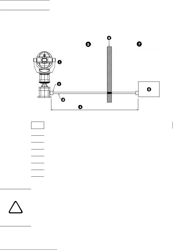
5.2 PSU Installation and Setup in a Non-Hazardous Area
The figure below illustrates an installation of a MIC PSU for MIC440 in a non-hazardous area. Note that the camera itself is installed in a hazardous area.
Figure 5.1: Installation of MIC PSU in Non-Hazardous Area
1 MIC440 camera
2Exd conduit gland
3 Composite cable inside metal conduit
4 Distance of 25 mm maximum
5 Hazardous area
6Exd Barrier
7 Non-hazardous Area
8Standard MIC PSU
5.3 |
PSU Installation and Setup in a Hazardous Area |
Caution!
Any junction box or enclosure used for mounting the power supply or separating cable cores MUST BE appropriately rated for the installation. MIC PSU enclosures are not Exd rated and
!must be placed inside a certified enclosure if installed within a hazardous area.
For additional protection in hazardous area installations, suitable metal conduit must be used externally for the composite cable run to connect the power supply to the Exd conduit gland (not supplied) in the Deep Conduit Adapter (MIC-DCA).
Bosch Security Systems, Inc. |
Operation Manual |
2013.11 | 8.1 | |
18 en | Installation of a MIC440 Camera |
MIC440 Explosion-protected Camera |
|
|
Installation of the PSU within a hazardous area must have the standard PSU enclosure placed inside an appropriate certified enclosure and four (4) Exd conduit glands (NOT supplied). The power supply PCB is usually re-housed, by a third party company, within an Exd enclosure which is then factory certified and shipped to site. Follow all manufacturers’ instructions when installing a third party Exd enclosure.
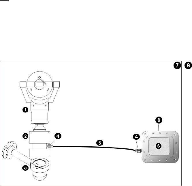
The figure below illustrates a typical installation of both a MIC440 and a MIC PSU in a hazardous area. Note that the PSU is installed inside an enclosure that is certified for use in hazardous areas.
Figure 5.2: Installation of MIC PSU in Hazardous Area
No. |
Description |
|
|
|
|
1 |
MIC440 camera |
|
|
|
|
2 |
MIC440 DCA |
|
|
|
|
3 |
MIC Wall Mount Bracket (not supplied) |
|
|
|
|
4 |
Exd conduit gland |
|
|
Exd Barrier Gland (not supplied; to be specified by installer to match incoming conduit) |
|
|
|
|
5 |
MIC composite cable (length to be specified; 25 m maximum) inside metal conduit (not supplied) |
|
|
|
|
6 |
MIC PSU |
|
|
|
|
7 |
Hazardous area |
|
|
|
|
8 |
Non-Hazardous area |
|
|
|
|
9 |
Exd Enclosure certified for hazardous areas (not supplied) |
|
|
|
|
|
|
|
2013.11 | 8.1 | |
Operation Manual |
Bosch Security Systems, Inc. |
Loading...