


MM100
MM100
1
2
3
4
5
6
7
8
9
10
0
EMS 2
EMS plus
5
6
4
7
3
8
2
9
1
100
6 720 808 385-00.1O
[de] Installationsanleitung für das Fachhandwerk 2
[en] Installation instructions for Installers 11
[es] Manual de instalaciones para el técnico especializado 20
[fl] Installatiehandleiding voor de installateur 31
[fr] Notice d’installation pour le professionnel 40
[it] Istruzioni per l'installazione per tecnici specializzati 51
[nl] Installatiehandleiding voor de installateur 62
[pt] Instruções de instalação para os técnicos especializados 71
[zh] 专业人员安装说明书 82
6 720 813 621 (2014/12)
2 | Inhaltsverzeichnis
Inhaltsverzeichnis
1 Symbolerklärung und Sicherheitshinweise . . . . . . . . 2
1.1 Symbolerklärung . . . . . . . . . . . . . . . . . . . . . . . . . . . 2
1.2 Allgemeine Sicherheitshinweise . . . . . . . . . . . . . . 2
2 Angaben zum Produkt . . . . . . . . . . . . . . . . . . . . . . . . . . 3
2.1 Wichtige Hinweise zur Verwendung . . . . . . . . . . . . 4
2.2 Lieferumfang . . . . . . . . . . . . . . . . . . . . . . . . . . . . . . 4
2.3 Technische Daten . . . . . . . . . . . . . . . . . . . . . . . . . . 4
2.4 Reinigung und Pflege . . . . . . . . . . . . . . . . . . . . . . . 5
2.5 Ergänzendes Zubehör . . . . . . . . . . . . . . . . . . . . . . . 5
3 Installation . . . . . . . . . . . . . . . . . . . . . . . . . . . . . . . . . . . . 6
3.1 Vorbereitung für die Installation im
Wärmeerzeuger . . . . . . . . . . . . . . . . . . . . . . . . . . . .6
3.2 Installation . . . . . . . . . . . . . . . . . . . . . . . . . . . . . . . 6
3.3 Elektrischer Anschluss . . . . . . . . . . . . . . . . . . . . . . 6
3.3.1 Anschluss BUS-Verbindung und
Temperaturfühler (Kleinspannungsseite) . . . . . . .6
3.3.2 Anschluss Spannungsversorgung, Pumpe,
Mischer und Temperaturwächter
(Netzspannungsseite) . . . . . . . . . . . . . . . . . . . . . . .6
3.3.3 Überblick Anschlussklemmenbelegung . . . . . . . . 7
3.3.4 Anschlusspläne mit Anlagenbeispielen . . . . . . . . . 8
4 Inbetriebnahme . . . . . . . . . . . . . . . . . . . . . . . . . . . . . . . . 9
4.1 Kodierschalter einstellen . . . . . . . . . . . . . . . . . . . . 9
4.2 Inbetriebnahme der Anlage und des Moduls . . . . 9
4.2.1 Einstellungen für Heizkreis . . . . . . . . . . . . . . . . . . . 9
4.2.2 Einstellungen für Speicherladekreis . . . . . . . . . . . 9
5 Störungen beheben . . . . . . . . . . . . . . . . . . . . . . . . . . . 10
6 Umweltschutz/Entsorgung . . . . . . . . . . . . . . . . . . . . . 10
1
Symbolerklärung und Sicherheitshinweise
1.1 Symbolerklärung
Warnhinweise
Warnhinweise im Text werden mit einem
Warndreieck gekennzeichnet.
Zusätzlich kennzeichnen Signalwörter die Art
und Schwere der Folgen, falls die Maßnahmen
zur Abwendung der Gefahr nicht befolgt werden.
Folgende Signalwörter sind definiert und können im vorliegenden Dokument verwendet sein:
• HINWEIS bedeutet, dass Sachsch äden auftreten können.
• VORSICHT bedeutet, dass leichte bis mittelschwere
Personenschäden auftreten können.
• WARNUNG bedeutet, da ss schwere bis lebensgefährliche
Personenschäden auftreten können.
• GEFAHR bedeutet, dass schwere bis lebensgefährliche
Personenschäden auftreten werden.
Wichtige Informationen
Wichtige Informationen ohne Gefahren für
Menschen oder Sachen werden mit dem nebenstehenden Symbol gekennzeichnet.
Weitere Symbole
Symbol Bedeutung
▶Handlungsschritt
Querverweis auf eine andere Stelle im Dokument
• Aufzählung/Listeneintrag
– Aufzählung/Listeneintrag (2. Ebene)
Tab. 1
1.2 Allgemeine Sicherheitshinweise
Diese Installationsanleitung richtet sich an Fachleute für Wa sserinstallationen, Heizungs- und Elektrotechnik.
▶ Installationsanleitungen (Wärmeerzeuger, Module, usw.)
vor der Installation lesen.
▶ Sicherheits- und Warnhinweise beachten.
▶ Nationale und regionale Vorschriften, technische Regeln
und Richtlinien beachten.
▶ Ausgeführte Arbeiten dokumentieren.
Bestimmungsgemäße Verwendung
▶ Produkt ausschließlich zur Regelung von Heizungsanlagen
in Ein- oder Mehrfamilienhäusern verwenden.
6 720 813 621 (2014/12) MM100
Jede andere Verwendung ist nicht bestimmungsgemäß. Daraus resultierende Schäden sind von der Haftung ausgeschlossen.
Installation, Inbetriebnahme und Wartung
Installation, Inbetriebnahme und Wartung darf nur ein zugelassener Fachbetrieb ausführen.
▶ Nur Originalersatzteile einbauen.
Elektroarbeiten
Elektroarbeiten dürfen nur Fachleute für Elektroinstallationen
ausführen.
▶ Vor Elektroarbeiten:
– Netzspannung (allpolig) spannungsfrei schalten und
gegen Wiedereinschalten sichern.
– Spannungsfreiheit feststellen.
▶ Produkt benötigt unterschiedliche Spannungen.
Kleinspannungsseite nicht an Netzspannung anschließen
und umgekehrt.
▶ Anschlusspläne weiterer Anlagenteile ebenfalls beachten.
Übergabe an den Betreiber
Weisen Sie den Betreiber bei der Übergabe in die Bedienung
und die Betriebsbedingungen der Heizungsanlage ein.
▶ Bedienung erklären – dabei besonders auf alle sicherheits-
relevanten Handlungen eingehen.
▶ Darauf hinweisen, dass Umbau oder Instandsetzungen nur
von einem zugelassenen Fachbetrieb ausgeführt werden
dürfen.
▶ Auf die Notwendigkeit von Inspektion und Wartung für den
sicheren und umweltverträglichen Betrieb hinweisen.
▶ Installations- und Bedienungsanleitungen zur Aufbewah-
rung an den Betreiber übergeben.
Schäden durch Frost
Wenn die Anlage nicht in Betrieb ist, kann sie einfrieren:
▶ Hinweise zum Frostschutz beachten.
▶ Anlage immer eingeschaltet lassen, wegen zusätzlicher
Funktionen, z. B. Warmwasserbereitung oder Blockierschutz.
▶ Auftretende Störung umgehend beseitigen.
Angaben zum Produkt | 3
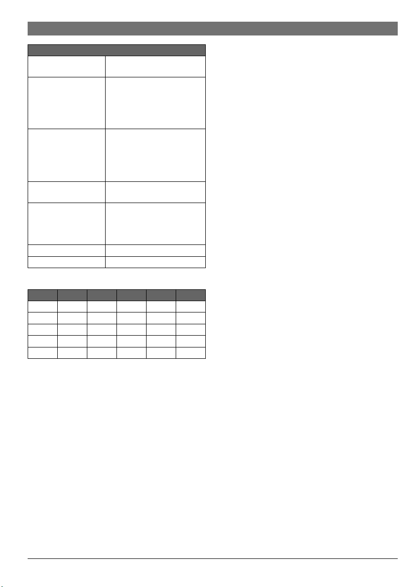
2Angaben zum Produkt
Im Folgenden wird ein Heiz-, Konstantheizoder Kühlkreis im Allgemeinen nur Heizkreis
genannt.
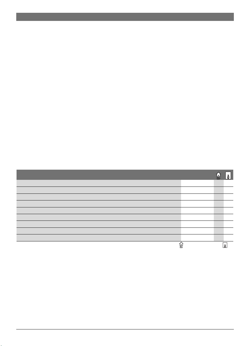
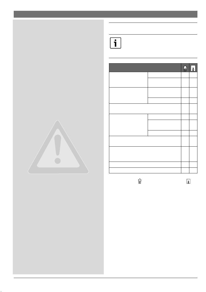
Funktion
max. 4 Heizkreise oder
max. 8 Heizkreise
hydraulische Anbindung
mehrerer Heizkreise
Vorlauftemperaturfühler – System (an T0) (z. B.
an einer hydraulischen Weiche)
mögliche Heizkreisfunktionen
Taupunktwächter (an MD1) für Heizkreisfunktion
Kühlen
externes Signal für Wärmeanforderung (an MD1),
Heizungspumpe ein/aus für Konstantheizkreis
Speicherladekreis 1 oder 2
Zirkulationspumpe –
Tab. 2 Funktionen des Moduls in Kombination mit Wärme-
pumpe ( ) oder anderem Wärmeerzeuger ( )
1) Nicht mit allen Bedieneinheiten möglich.
2) Maximal ein ungemischter Heizkreis empfohlen
3) In den Anlagenbeispielen nicht dargestellt.
4) Für konstante Vorlauftemperatur z. B. Pool- oder Warmluftheizung.
5) Warmwasserspeicher nach hydraulischer Weiche.
• Das Modul dient zur Ansteuerung
– eines Heizkreises (bei Wärmepumpen auch Kühlkreis)
mit einer Heizungspumpe und mit oder ohne Mischermotor
– eines Speicherladekreises mit getrennter Speicherla-
depumpe und Zirkulationspumpe (Zirkulationspumpe
optional).
• Das Modul dient zur Erfassung
– der Vorlauftemperatur im zugeord neten Heizkreis oder
der Temperatur des Warmwasserspeichers
–
der Temperatur an einer hydraulischen Wei che (optional)
gemischt
1)
ungemischt
2)
hydraulische Weiche –
Pufferspeicher
Heizen
Konstantheizkreis
Kühlen –
5)
3)
4)
–
–
–
–
6 720 813 621 (2014/12)MM100
4 | Angaben zum Produkt
– des Steuersignals eines Temperaturwächters im zuge-
ordneten Heizkreis (bei ungemischtem Heizkreis optional).
– des Steuersignals eines Taupunktwächters im zugeord-
neten Kühlkreis
• Blockierschutz:
– Die angeschlossene Pumpe wird überwacht un d nach
24 Stunden Stillstand automatisch für kurze Zeit in Betrieb genommen. Dadurch wird ein Festsitzen der Pumpe verhindert.
– Der angeschlossene Mischermotor wird überwacht
und nach 24 Stunden Stillstand automatisch für kurze
Zeit in Betrieb genommen. Dadurch wird ein Festsitzen
des Mischers verhindert.
Unabhängig von der Anzahl anderer BUS-Teilnehmer, sind je
nach installierter Bedieneinheit maximal 6 oder 10 MM100 in
einer Anlage erlaubt.
Im Auslieferungszustand ist der Kodierschalter auf Position 0.
Nur wenn der Kodierschalter auf einer gültigen Position für
Heizkreis oder Speicherladekreis (meist hinter der hydraulischen Weiche) steht, ist das Modul in der Bedieneinheit angemeldet.
Ein Anlagenbeispiel mit 3 gemischten Heizkreisen, einem ungemischten Heizkreis und einem Speicherladekreis ist in Bild 24
auf Seite 103 dargestellt. Ein weiteres Beispiel mit 3 und mehr
Heizkreisen und 2 Speicherladekreisen ist in Bild 27 auf
Seite 106 dargestellt.
2.1 Wichtige Hinweise zur Verwendung
WARNUNG: Verbrühungsgefahr!
▶ Wenn Warmwassertemperaturen über
60 °C eingestellt werden oder die thermische Desinfektion eingeschaltet ist, muss
eine Mischvorrichtung installiert werden.
HINWEIS: Schäden am Fußboden!
▶ Fußbodenheizung nur mit zusätzlichem
Temperaturwächter betreiben.
HINWEIS: Anlagenschaden!
Wenn ein Heizkreis in Verbindung mit einer
Wärmepumpe (Heizen/Kühlen) installiert ist,
kann Kondensat an kühlen Anlagenteilen zu
Schäden Führen.
▶ Diesen Heizkreis nur mit Taupunktwächter
betreiben.
Das Modul kommuniziert über eine EMS 2/EMS plus Schnittstelle mit anderen EMS 2/EMS plus fähigen BUS-Teilnehmern.
• Das Modul darf ausschließlich an Bedieneinheiten mit BUSSchnittstelle EMS 2/EMS plus (Energie-Management-System) angeschlossen werden.
• Der Funktionsumfang ist von der installierten Bedieneinheit abhängig. Genaue Angaben zu Bedieneinheiten entnehmen Sie bitte dem Katalog, den Planungsunterlagen
und der Webseite des Herstellers.
• Der Installationsraum muss für die Schutzart gemäß den
technischen Daten des Moduls geeignet sein.
2.2 Lieferumfang
Bild 1, Seite 91:
[1] Modul
[2] Brücke zum Anschluss an MC1, wenn kein Temperatur-
wächter im zugeordneten (ungemischten) Heizkreis
[3] Beutel mit Zugentlastungen
[4] Installations-Set Vorlauftemperaturfühler
[5] Installationsanleitung
2.3 Technische Daten
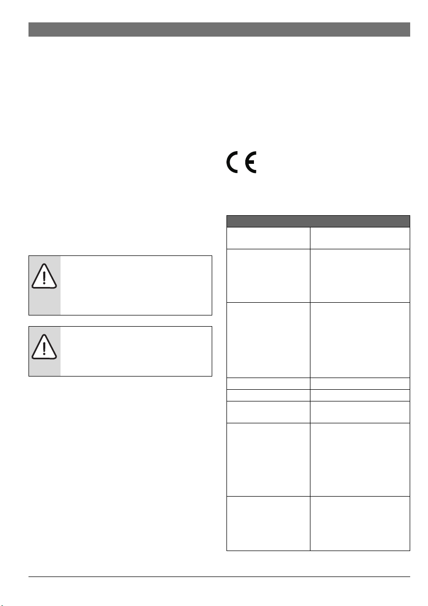
Dieses Produkt entspricht in Konstruktion und
Betriebsverhalten den europäischen Richtlinien
gen. Die Konformität wurde mit der CE-Kennzeichnung nachgewiesen. Sie können die Konformitätserklärung des Produkts
anfordern. Wenden Sie sich dazu an die Adresse auf der Rückseite dieser Anleitung.
Technische Daten
Abmessungen
(B×H×T)
Maximaler Leiterquerschnitt
• Anschlussklemme
• Anschlussklemme
Nennspannungen
•BUS
• Spannungsversor-
• Bedieneinheit
•Pumpe u. Mischer
Sicherung 230 V, 5 AT
BUS-Schnittstelle EMS 2/EMS plus
Tab. 3
sowie den ergänzenden nationalen Anforderun-
151 × 184 × 61 mm (weitere
Maße Bild 2, Seite 91)
230 V
•2,5 mm
•1,5 mm
2
2
Kleinspannung
• 15 V DC (verpolungssicher)
• 230 V AC, 50 Hz
gung des Moduls
• 15 V DC (verpolungssicher)
• 230 V AC, 50 Hz
6 720 813 621 (2014/12) MM100
Angaben zum Produkt | 5
Technische Daten
Leistungsaufnahme –
Standby
maximale Leistungsabgabe
• pro Anschluss (PC1)
• pro Anschluss (VC1)
Messbereich Temperaturfühler
• untere Fehlergrenze
•Anzeigebereich
•obere Fehlergrenze
zulässige Umgebungstemperatur
Schutzart
• bei Einbau in Wärmeerzeuger
• bei Wandinstallation
Schutzklasse I
Ident.-Nr. Typschild ( Bild 18, Seite 97)
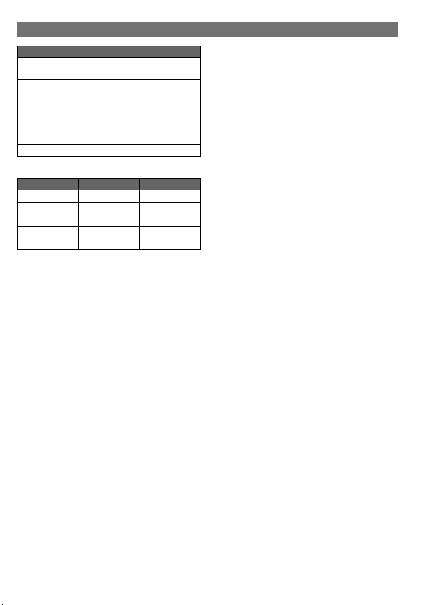
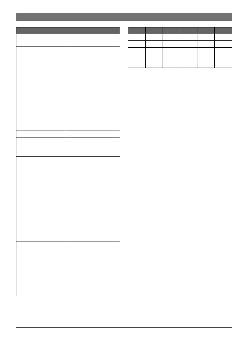
Tab. 3
°C °C °C
8 25065 38 7174 68 2488
14 19170 44 5730 74 2053
20 14772 50 4608 80 1704
26 11500 56 3723 86 1421
32 9043 62 3032 – –
Tab. 4 Messwerte Vorlauftemperaturfühler (im Lieferum-
fang enthalten)
< 1 W
• 400 W (Hocheffizienzpumpen zulässig; max. 40 A/s)
• 100 W
•<– 10°C
• 0 ... 100 °C
• > 125 °C
0 ... 60 °C
• wird von Schutzart des Wärmeerzeugers bestimmt
•IP44
2.4 Reinigung und Pflege
▶ Bei Bedarf mit einem feuchten Tuch das Gehäuse abreiben.
Dabei keine scharfen oder ätzenden Reinigungsmittel verwenden.
2.5 Ergänzendes Zubehör
Genaue Angaben zu geeignetem Zubehör entnehmen Sie bitte
dem Katalog.
• Für gemischten, ungemischten Heizkreis und Konstantheizkreis:
– Heizungspumpe; Anschluss an PC1
– Vorlauftemperaturfühler – System (optional; nicht mit
allen Bedieneinheiten möglich); Anschluss an T0
– Temperaturwächter; Anschluss an MC1; unterbricht
bei Überschreiten der Grenztemperatur die Spannungsversorgung an Anschlussklemme 63 - PC1; wenn
kein Temperaturwächter im ungemischten Heizkreis
oder im Konstantheizkreis, Brücke ( Bild 1 [2],
Seite 91) an MC1 anschließen.
• Zusätzlich für gemischten Heizkreis:
– Mischermotor; Anschluss an VC1
– Vorlauftemperaturfühler im zugeordneten Heizkreis;
Anschluss an TC1
• Zusätzlich für einen Heizkreis in Verbindung mit einer Wärmepumpe (Heizen/Kühlen):
– Taupunktwächter; Anschluss an MD1; sendet bei Errei-
chen des Taupunkts ein Signal an die Regelung, um
Kondensatbildung durch weiteres Abkühlen zu vermeiden und stoppt die Heizungspumpe
•Zusätzlich für einen Konstantheizkreis:
–externes Signal für Wärmeanforderung; Anschluss an
MD1 (nur wenn die externe Wärmeanforderung an der
Bedieneinheit freigegeben ist, wird die Pumpe einge-
schaltet)
– Mischermotor (optional); Anschluss an VC1
– Vorlauftemperaturfühler im zugeordneten Heizkreis
(optional); Anschluss an TC1
• Für Speicherladekreis (z. B. nach hydraulischer Weiche):
– Speicherladepumpe; Anschluss an PC1; Brücke
( Bild 1 [2], Seite 91) an MC1 anschließen
– Zirkulationspumpe (optional); Anschluss an VC1
(Anschlussklemme 43: Zirkulationspumpe Phase /
Anschlussklemme 44: nicht belegt)
– Vorlauftemperaturfühler hydraulische Weiche
(optional; nicht mit allen Bedieneinheiten möglich);
Anschluss an T0
– Speichertemperaturfühler; Anschluss an TC1.
Installation des ergänzenden Zubehörs
▶ Ergänzendes Zubehör entsprechend den gesetzlichen Vor-
schriften und der mitgelieferten Anleitungen installieren.
Wenn in der mitgelieferten Anleitung des Taupunktwächters
oder der Wärmepumpe nicht anders gefordert:
▶ Taupunktfühler möglichst nahe am Pufferspeicher oder an
der kühlsten Stelle der Anlage installieren.
▶ Maximal 4 Taupunktwächter parallel an MD1 anschließen.
6 720 813 621 (2014/12)MM100
6 | Installation
3 Installation
GEFAHR: Stromschlag!
▶ Vor Installation dieses Produktes: Wär-
meerzeuger und alle weiteren BUS-Teilnehmer allpolig von der Netzspannung
trennen.
▶ Vor Inbetriebnahme: Abdeckung anbringen
( Bild 17, Seite 96).
3.1 Vorbereitung für die Installation im Wärmeerzeuger
▶ Über die Installationsanleitung des Wärmeerzeugers über-
prüfen, ob dieser die Möglichkeit bietet, Module (z. B.
MM100) im Wärmeerzeuger zu installieren.
▶ Wenn das Modul ohne Hutschiene im Wärmeerzeuger ins-
talliert werden kann, Modul vorbereiten ( Bild3 und5,
Seite 92).
▶ Wenn das Modul mit Hutschiene im Wärmeerzeuger instal-
liert werden kann, Bild 8 und 11, Seite 94 beachten.
3.2 Installation
▶ Modul an einer Wand ( Bild 3 bis Bild 7, Seite 93 und
Seite 14), an einer Hutschiene ( Bild 8, Seite 93) oder
im Wärmeerzeuger installieren. Bei der Installation des Moduls in einem Wärmeerzeuger, die Anleitung des Wärmeerzeugers beachten.
▶ Beim Entfernen des Moduls von der Hutschiene Bild 8 auf
Seite 93 beachten.
▶ Vorlauftemperaturfühler im zugeordneten gemischten
Heizkreis installieren.
3.3 Elektrischer Anschluss
▶ Unter Berücksichtigung der geltenden Vorschriften für den
Anschluss mindestens Elektrokabel der Bauart H05 VV-...
verwenden.
3.3.1 Anschluss BUS-Verbindung und Temperaturfühler
(Kleinspannungsseite)
▶ Bei unterschiedlichen Leiterquerschnitten Verteilerdose
für den Anschluss der BUS-Teilnehmer verwenden.
▶ BUS-Teilnehmer [B] über Verteilerdose [A] in Stern
( Bild 15, Seite 96) oder über BUS-Teilnehmer mit zwei
BUS-Anschlüssen in Reihe ( Bild 19, Seite 98) schalten.
Wenn die maximale Gesamtlänge der BUS-Verbindungen zwischen allen BUS-Teilnehmern
überschritten wird oder im BUS-System eine
Ringstruktur vorliegt, ist die Inbetriebnahme
der Anlage nicht möglich.
Maximale Gesamtlänge der BUS-Verbindungen:
• 100 m mit 0,50 mm
• 300 m mit 1,50 mm
2
Leiterquerschnitt
2
Leiterquerschnitt
▶ Um induktive Beeinflussungen zu vermeiden: Alle
Kleinspannungskabel von Netzspannung führenden Kabeln
getrennt verlegen (Mindestabstand 100 mm).
▶ Bei induktiven äußeren Einflüssen (z. B. von PV-Anlagen)
Kabel geschirmt ausführen (z. B. LiYCY) und Schirmung
einseitig erden. Schirmung nicht an Anschlussklemme für
Schutzleiter im Modul anschließen, sondern an Hauserdung, z. B. freie Schutzleiterklemme oder Wasserrohre.
Nur einen Temperaturfühler T0 pro Anlage installieren. Wenn mehrere Module vorhanden
sind, ist das Modul für den Anschluss des Temperaturfühlers T0 frei wählbar.
Bei Verlängerung der Fühlerleitung folgende Leiterquerschnitte verwenden:
• Bis 20 m mit 0,75 mm
• 20 m bis 100 m mit 1,50 mm
2
bis 1,50 mm2 Leiterquerschnitt
2
Leiterquerschnitt
▶ Kabel durch die bereits vormontierten Tüllen führen und
gemäß den Anschlussplänen anklemmen.
3.3.2 Anschluss Spannungsversorgung, Pumpe, Mischer
und Temperaturwächter (Netzspannungsseite)
Die Belegung der elektrischen Anschlüsse ist
von der installierten Anlage abhängig. Die in
Bild 11 bis 14, ab Seite 94 dargestellte Beschreibung ist ein Vorschlag für den Ablauf des
elektrischen Anschlusses. Die Handlungsschritte sind teilweise nicht schwarz dargestellt. Damit ist leichter zu erkennen, welche
Handlungsschritte zusammengehören.
▶ Nur Elektrokabel gleicher Qualität verwenden.
▶ Auf phasenrichtige Installation des Netzanschlusses
achten.
Netzanschluss über einen Schutzkontaktstecker ist
nicht zulässig.
▶ An den Ausgängen nur Bauteile und Baugruppen gemäß
dieser Anleitung anschließen. Keine zusätzlichen
Steuerungen anschließen, die weitere Anlagenteile
steuern.
▶ Kabel durch die Tüllen führen, gemäß den Anschlussplänen
anklemmen und mit den im Lieferumfang enthaltenen Zugentlastungen sichern ( Bild 11 bis 14, ab Seite 94).
6 720 813 621 (2014/12) MM100
Installation | 7
0
1
2
3
4
5
6
7
8
9
10
Die maximale Leistungsaufnahme der angeschlossenen Bauteile und Baugruppen darf die
in den technischen Daten des Moduls angegebene Leistungsabgabe nicht überschreiten.
▶ Wenn die Netzspannungsversorgung nicht
über die Elektronik des Wärmeerzeugers
erfolgt, bauseits zur Unterbrechung der
Netzspannungsversorgung eine allpolige
normgerechte Trennvorrichtung (nach
EN 60335-1) installieren.
VC1
120/230 V AC
N7475
NL
M
PW2*
120/230VAC 120/230VAC
N L N N 43 N 6344 15 16L
230 V AC 230 V AC
4
NMN
VC1
PW2*
43 44
M
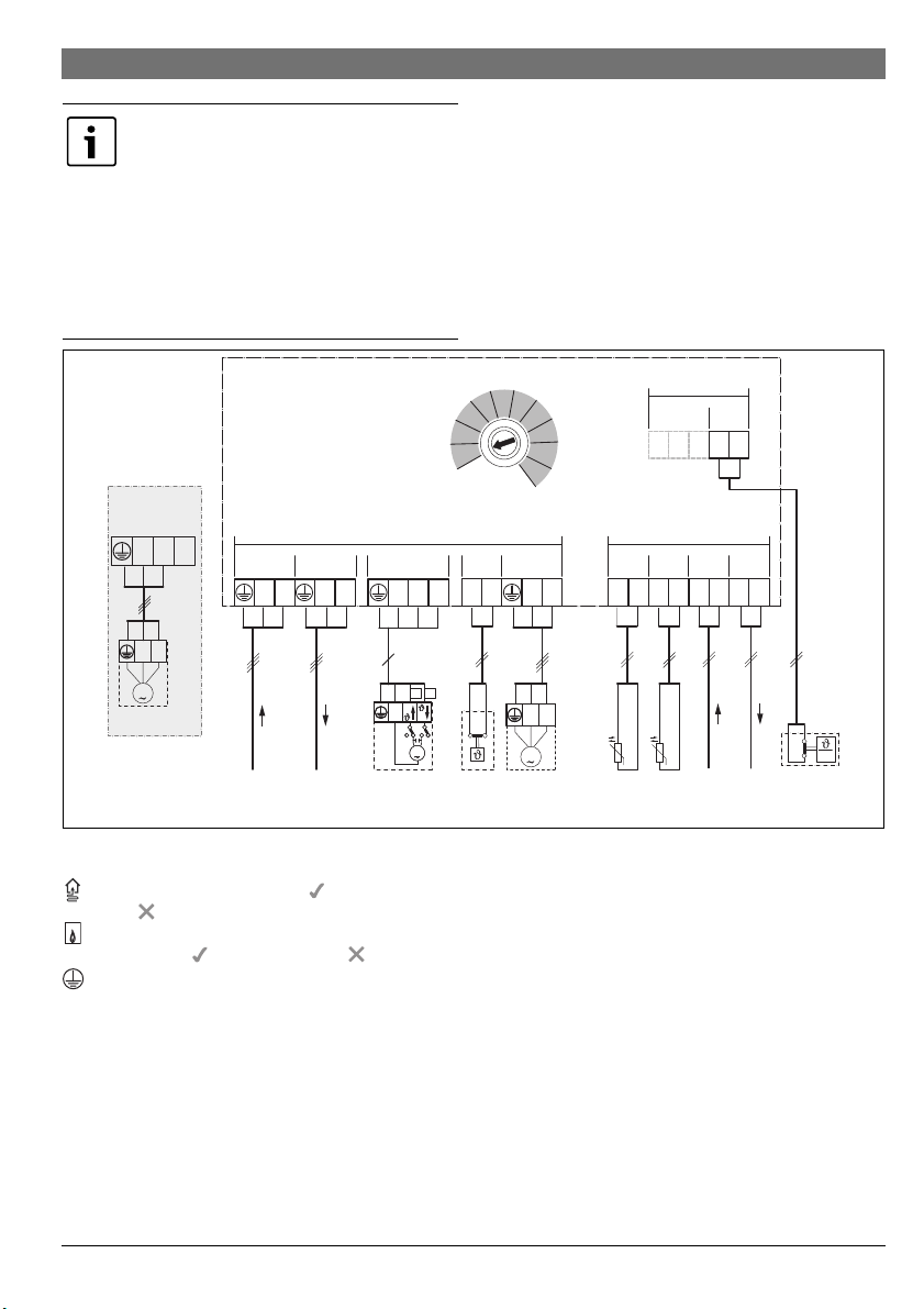
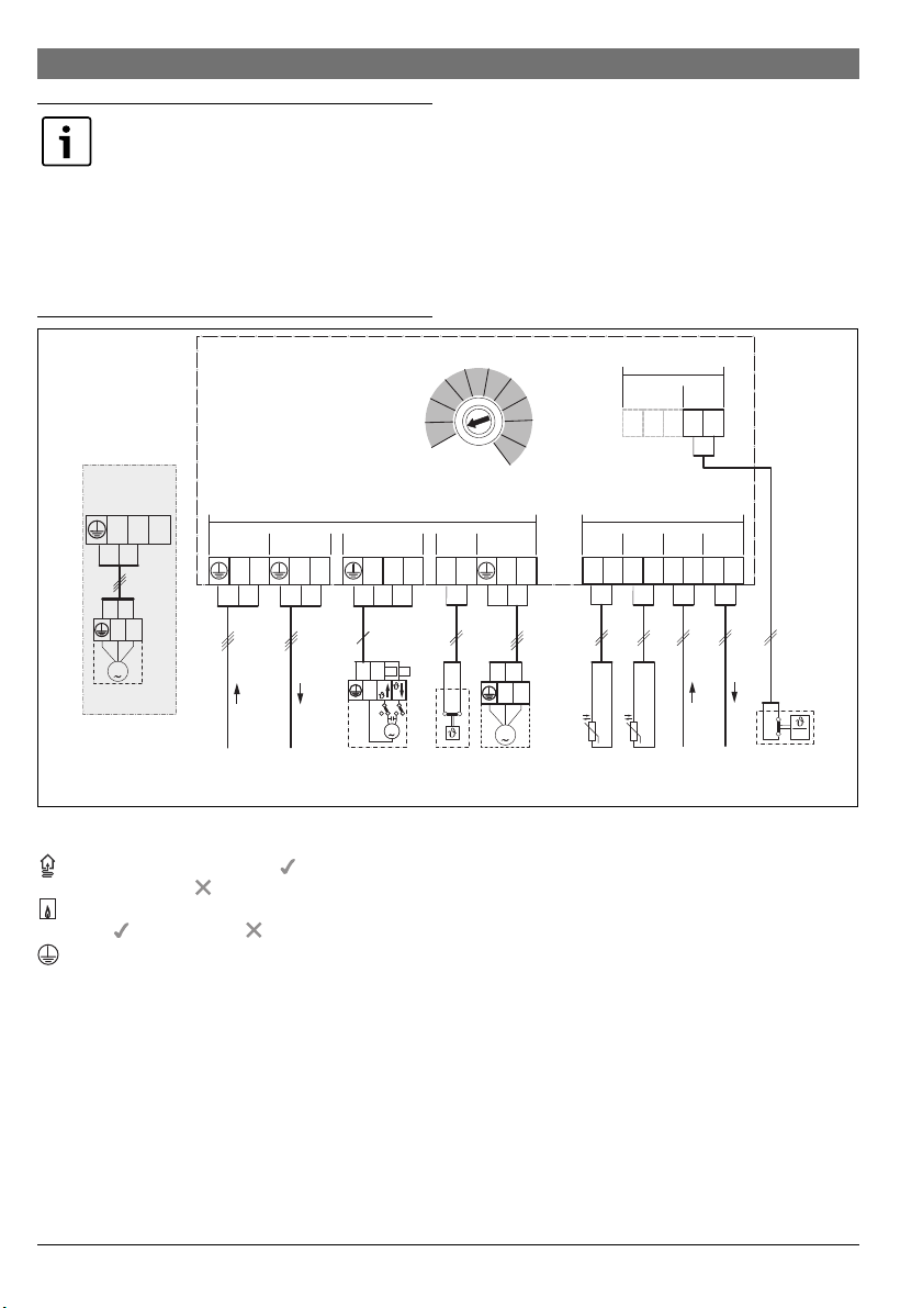
3.3.3 Überblick Anschlussklemmenbelegung
Dieser Überblick zeigt, welche Anlagenteile angeschlossen
werden können. Die mit * gekennzeichneten Bauteile der Anlage sind alternativ möglich. Je nach Verwendung des Moduls
(Kodierung am Modul und Konfiguration über die Bedieneinheit) wird eines der Bauteile an der Anschlussklemme angeschlossen (z. B. „PC1“ oder „PW1“ an der Anschlussklemme
„PC1“). Die Anlagenteile sind gemäß dem jeweiligen Anschlussplan anzuschließen ( Tab „Anschlusspläne mit Anlagenbeispielen“).
MM100
1)
10
≤ 24V
OC131MD1
12 2
≤ 24V
MC1VC1 PC1
PC1
MC1
PW1*
T0 BUS
1212 12
NL
M
TC1
TW1*
BUS
12
BUS BUST0 TC1
MD1
6 720 810 981-01.2O
%-rel
Legende zum Bild oben und zu Bild 19 bis 27, ab Seite 98:
mit Wärmepumpe möglich ( ) oder nicht möglich
()
mit anderen Wärmeerzeugern als Wärmepumpen
möglich ( ) oder nicht möglich ( )
Schutzleiter
Temperatur/Temperaturfühler
LPhase (Netzspannung)
N Neutralleiter
Anschlussklemmenbezeichnungen:
230 V AC Anschluss Netzspannung
BUS Anschluss BUS-System EMS 2
MC1 Temperaturwächter (Monitor Circuit)
MD1 Potentialfreier Kontakt (Monitor Dew point):
bei Kühlen (Kühlfunktion): Taupunkt erreicht/Tau-
punkt nicht erreicht (%rel)
bei Konstantheizkreis: externes Signal für Wärmeanforderung () – Heizungspumpe ein/aus
( Ergänzendes Zubehör)
OC1 ohne Funktion
PC1 Anschluss Pumpe (Pump Circuit)
T0 Anschluss Temperaturfühler an der hydraulischen
Weiche oder am Pufferspeicher (Temperature sensor)
TC1 Anschluss Temperaturfühler Heizkreis oder Spei-
chertemperaturfühler (Temperature sensor Circuit)
VC1 Anschluss Mischermotor (Valve Circuit):
Anschlussklemme 43: Mischer auf (bei Heizung
wärmer; bei Kühlen (Kühlfunktion): kälter)
Anschlussklemme 44: Mischer zu (bei Heizung
kälter; bei Kühlen (Kühlfunktion): wärmer)
6 720 813 621 (2014/12)MM100
8 | Installation
-oder-
Anschluss Zirkulationspumpe im Warmwasserkreis
(Kodierschalter auf 9 oder 10):
Anschlussklemme 43: Zirkulationspumpe Phase
Anschlussklemme 44: nicht belegt
Bestandteile der Anlage:
230 V AC Netzspannung
BT Pufferspeicher (Buffer Tank)
BUS BUS-System EMS 2/EMS plus
CON Bedieneinheit EMS 2/EMS plus (Control)
HS... Wärmeerzeuger (Heat Source)
HS1: Heizgerät, z. B. Gas-Brennwertgerät
HS2: Heizkessel, z. B. Gas-Heizwertkessel
HS3: Wärmepumpe, z. B. Luft-Wasser-Wärmepumpe
IC1 Schaltkontakt für externe Wärmeanforderung
()im zugeordnetenHeizkreis, Ergänzendes
Zubehör
MC1 Temperaturwächter im zugeordneten Heizkreis
MD1 Taupunktwächter (%rel) im zugeordneten Heiz-
MM100 Modul MM100
PC1 Heizungspumpe im zugeordneten Heizkreis
PW1 Speicherladepumpe im zugeordneten Speicherla-
PW2 Zirkulationspumpe im zugeordneten Warmwasser-
T0 Vorlauftemp eraturfühler an der hydraulischen Wei-
TC1 Vorlauftemperaturfühler im zugeordneten Heizkreis
TW1 Speichertemperaturfühler im zugeordneten Spei-
VC1 Mischermotor im zugeordneten gemischten Heiz-
Temperaturwächter, Brücke ( Bild 1 [2],
Seite 91) an Anschlussklemme MC1 anschließen
kreis, Ergänzendes Zubehör
dekreis, z. B. nach hydraulischer Weiche (Kodierschalter auf 9 oder 10)
system (Kodierschalter auf 9 oder 10)
che oder am Pufferspeicher optional
cherladekreis (Kodierschalter auf 9 oder 10)
kreis
(bei ungemischtem Heizkreis optional; wenn kein
1) Je nach installierter Bedieneinheit maximal 4 oder 8
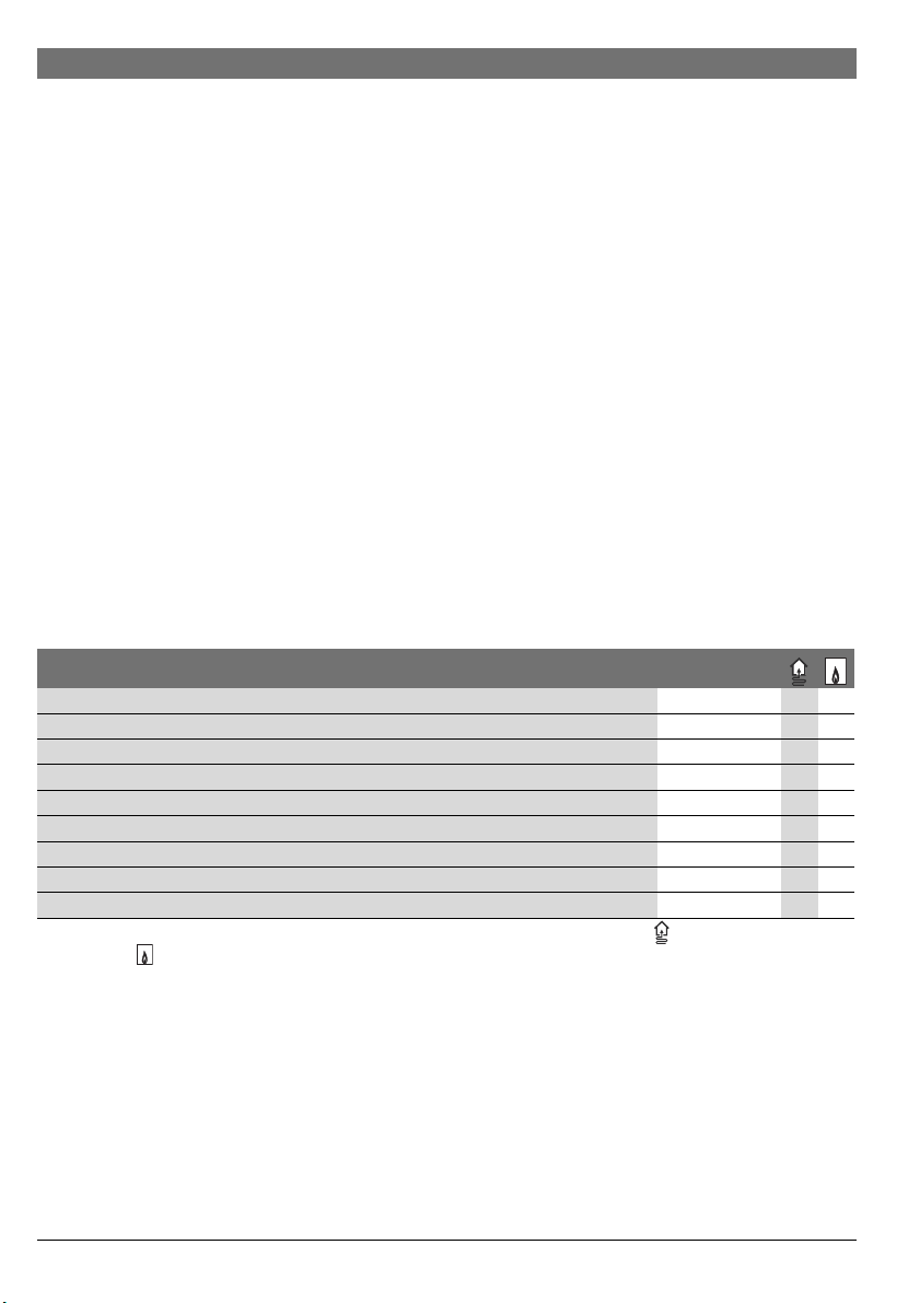
3.3.4 Anschlusspläne mit Anlagenbeispielen
Die hydraulischen Darstellungen sind nur schematisch und geben einen unverbindlichen Hinweis auf eine mögliche hydraulische Schaltung.
▶ Sicherheitseinrichtungen nach den gültigen Normen und
örtlichen Vorschriften ausführen.
▶ Weitere Informationen und Möglichkeiten den Planungsun-
terlagen oder der Ausschreibung entnehmen.
Funktion Heizkreis Bild / Seite
gemischt 19 / 98
Heizen/Kühlen 20 / 99 –
ungemischt 21 / 100
Speicherladekreis mit getrennter Speicherladepumpe1) und Zirkulationspumpe 22 / 101 –
konstant 23 / 102 –
1 ungemischt, 3 gemischt, 1 Speicherladekreis mit Heizgerät 24 / 103 –
1 ungemischt, 3 gemischt, 1 Speicherladekreis mit Heizkessel 25 / 104 –
1 ungemischt, 3 gemischt, Warmwasser mit Wärmepumpe 26 / 105 –
1 ungemischt, 2 oder mehr gemischt, 2 Speicherladekreise mit Heizgerät 27 / 106 –
Tab. 5 Anschlusspläne mit Anlagenbeispielen für das Modul in Kombination mit Wärmepumpe ( ) oder anderem Wärmeerzeu-
ger ( )
1) z. B. nach hydraulischer Weiche
6 720 813 621 (2014/12) MM100
Inbetriebnahme | 9
4Inbetriebnahme
Alle elektrischen Anschlüsse richtig anschließen und erst danach die Inbetriebnahme
durchführen!
▶ Installationsanleitungen aller Bauteile und
Baugruppen der Anlage beachten.
▶ Darauf achten, dass nicht mehrere Module
gleich kodiert sind.
▶ Spannungsversorgung nur einschalten,
wenn alle Module eingestellt sind.
HINWEIS: Nach dem Einschalten können angeschlossene Pumpen sofort zu laufen beginnen, solange die Regelung das Modul nicht
erkannt hat.
▶Vor dem Einschalten die Anlage befüllen,
damit die Pumpen nicht trocken laufen.
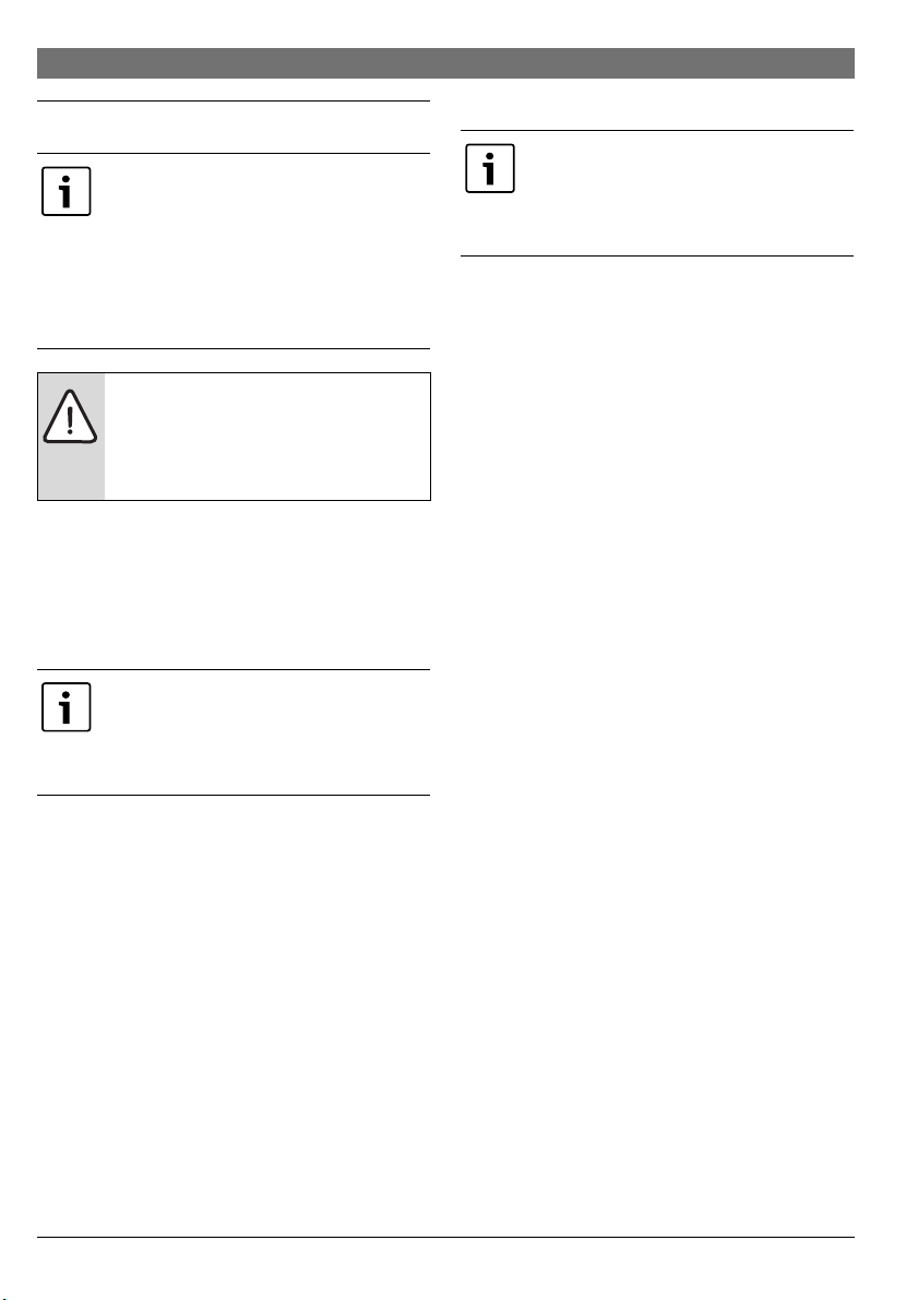
4.1 Kodierschalter einstellen
Wenn der Kodierschalter auf einer gültigen Position steht,
leuchtet die Betriebsanzeige dauerhaft grün. Wenn der Kodierschalter auf einer ungültigen Position oder in Zwischenstellung
steht, leuchtet die Betriebsanzeige zunächst nicht und beginnt
dann rot zu blinken.
Heizkreise über Kodierschalter zuordnen:
Wenn ein Heizkreis direkt am Wärmeerzeuger
angeschlossen ist, darf an keinem Modul der
Kodierschalter auf 1 gestellt werden. Der erste
Heizkreis hinter der hydraulischen Weiche ist
in diesem Fall Heizkreis 2.
Wenn ein Speicherladekreis direkt am Wärmeerzeuger angeschlossen ist, darf an keinem Modul
der Kodierschalter auf 9 gestellt werden. Der
Speicherladekreis hinter der hydraulischen
Weiche ist in diesem Fall Speicherladekreis 2.
• 1 Speicherladekreis: Kodierschalter auf 9
• 2 Speicherladekreise:
Speicherladekreis 1 = Kodierschalter auf 9;
Speicherladekreis 2 = Kodierschalter auf 10
4.2 Inbetriebnahme der Anlage und des Moduls
4.2.1 Einstellungen für Heizkreis
1. Modul einem Heizkreis zuordnen (je nach installierter Bedieneinheit 1 ... 8).
2. Ggf. Kodierschalter an weiteren Modulen einstellen.
3. Der gesamten Anlage die Netzspannung zuschalten.
Wenn die Betriebsanzeige des Moduls dauernd grün leuchtet:
4. Bedieneinheit gemäß beiliegender Installationsanleitung in
Betrieb nehmen und entsprechend einstellen.
4.2.2 Einstellungen für Speicherladekreis
1. Modul einem Speicherladekreis (9 ... 10) zuordnen.
2. Ggf. Kodierschalter an weiteren Modulen einstellen.
3. Der gesamten Anlage die Netzspannung zuschalten.
Wenn die Betriebsanzeige des Moduls dauernd grün leuchtet:
4. Bedieneinheit gemäß beiliegender Installationsanleitung in
Betrieb nehmen und entsprechend einstellen.
•1 Heizkreis:
Kodierschalter auf 1
•2 Heizkreise:
Heizkreis 1 = Kodierschalter auf 1;
Heizkreis 2 = Kodierschalter auf 2
•3 Heizkreise:
Heizkreis 1 = Kodierschalter auf 1;
Heizkreis 2 = Kodierschalter auf 2;
Heizkreis 3 = Kodierschalter auf 3 u.s.w.
Speicherladekreis (1 oder 2) über Kodierschalter zuordnen:
6 720 813 621 (2014/12)MM100

10 | Störungen beheben
0
1
2
3
4
5
6
7
8
9
10
6 720 645 409-20.1o
5 Störungen beheben
Die Betriebsanzeige zeigt den Betriebszustand des Moduls.
Nur Originalersatzteile verwenden. Schäden,
die durch nicht vom Hersteller gelieferte Ersatzteile entstehen, sind von der Haftung ausgeschlossen.
Wenn sich eine Störung nicht beheben lässt,
bitte an den zuständigen Servicetechniker
wenden.
Betriebsanzeige Mögliche Ursache Abhilfe
dauernd aus Kodierschalter auf 0 ▶ Kodierschalter einstellen.
Spannungsversorgung unterbrochen. ▶ Spannungsversorgung einschalten.
Sicherung defekt ▶ Bei ausgeschalteter Spannungsversorgung Sicherung austau-
Kurzschluss in der BUS-Verbindung ▶ BUS-Verbindung prüfen und ggf. instandsetzen.
dauernd rot interne Störung ▶ Modul austauschen.
rot blinkend Kodierscha lter auf ungültiger Position
oder in Zwischenstellung
Temperaturbegrenzer an MC1 (15-16)
ist nicht angeschlossen
grün blinkend maximale Kabellänge BUS-Verbindung
überschritten
Störungsanzeige im Display der
Bedieneinheit
dauernd grün keine Störung Normalbetrieb
Tab. 6
Wenn am Modul eine Störung auftritt, wird der Mischer im angeschlossenen gemischten Heizkreis auf eine vom Modul festgelegte Position gestellt. Dadurch ist es möglich, die Anlage mit
reduzierter Wärmeleistung weiter zu betreiben.
Einige Störungen werden auch im Display der dem Heizkreis
zugeordneten und ggf. der übergeordneten Bedieneinheit angezeigt.
schen ( Bild 16, Seite 96).
▶ Kodierschalter einstellen.
▶ Brücke oder Temperaturbegrenzer an MC1 anschließen.
▶ Kürzere BUS-Verbindung herstellen.
▶ Zugehörige Anleitung der Bedieneinheit und das Servicehand-
buch enthalten weitere Hinweise zur Störungsbehebung.
Alle verwendeten Verpackungsmaterialien sind umweltverträg-
6 Umweltschutz/Entsorgung
Umweltschutz ist ein Unternehmensgrundsatz der Bosch Gruppe.
Qualität der Produkte, Wirtschaftlichkeit und Umweltschutz
sind für uns gleichrangige Ziele. Gesetze und Vorschriften zum
Umweltschutz werden strikt eingehalten.
Zum Schutz der Umwelt setzen wir unter Berücksichtigung
wirtschaftlicher Gesichtspunkte bestmögliche Technik und
Materialien ein.
Verpackung
Bei der Verpackung sind wir an den länderspezifischen Verwer-
lich und wiederverwertbar.
Elektro- und Elektronik-Altgeräte
Nicht mehr gebrauchsfähige Elektro- oder
Elektronikgeräte müssen getrennt gesammelt
und einer umweltgerechten Verwertung zugeführt werden (Europäische Richtlinie über
Elektro- und Elektronik-Altgeräte).
Nutzen Sie zur Entsorgung von Elektro- oder
Elektronik-Altgeräten die länderspezifischen
Rückgabe- und Sammelsysteme.
tungssystemen beteiligt, die ein optimales Recycling gewährleisten.
6 720 813 621 (2014/12) MM100

Contents | 11
Contents
1 Key to symbols and safety instructions . . . . . . . . . . 11
1.1 Key to symbols . . . . . . . . . . . . . . . . . . . . . . . . . . . 11
1.2 General safety instructions . . . . . . . . . . . . . . . . . 11
2 Product details . . . . . . . . . . . . . . . . . . . . . . . . . . . . . . . 12
2.1 Important notices on usage . . . . . . . . . . . . . . . . . 13
2.2 Standard delivery . . . . . . . . . . . . . . . . . . . . . . . . . 13
2.3 Technical data . . . . . . . . . . . . . . . . . . . . . . . . . . . . 13
2.4 Cleaning and care . . . . . . . . . . . . . . . . . . . . . . . . . 14
2.5 Supplementary accessories . . . . . . . . . . . . . . . . . 14
3 Installation . . . . . . . . . . . . . . . . . . . . . . . . . . . . . . . . . . . 15
3.1 Preparation for installation in the heat source . . 15
3.2 Installation . . . . . . . . . . . . . . . . . . . . . . . . . . . . . . 15
3.3 Electrical connection . . . . . . . . . . . . . . . . . . . . . . 15
3.3.1 Connecting the BUS connection and
temperature sensor (extra-low voltage side) . . . 15
3.3.2 Connecting the power supply, pump and
mixing valve and temperature switch
(mains voltage side) . . . . . . . . . . . . . . . . . . . . . . . 15
3.3.3 Overview of the terminal assignment . . . . . . . . . 16
3.3.4 Connection diagrams with system schematics . 17
4 Commissioning . . . . . . . . . . . . . . . . . . . . . . . . . . . . . . . 18
4.1 Setting the coding card . . . . . . . . . . . . . . . . . . . . 18
4.2 System and module commissioning . . . . . . . . . . 18
4.2.1 Settings for heating circuit . . . . . . . . . . . . . . . . . 18
4.2.2 Settings for cylinder primary circuit . . . . . . . . . . 18
5 Troubleshooting . . . . . . . . . . . . . . . . . . . . . . . . . . . . . . 19
6 Environment / disposal . . . . . . . . . . . . . . . . . . . . . . . . 19
1 Key to symbols and safety instructions
1.1 Key to symbols
Warnings
Warnings in this document are identified by
a warning triangle printed against a grey
background.
Keywords at the start of a warning indicate
the type and seriousness of the ensuing risk
if measures to prevent the risk are not taken.
The following keywords are defined and can be used in this
document:
• NOTI CE indicates a situation that could result in damage to
property or equipment.
• CAUT ION indicates a situation that could result in minor to
medium injury.
• WARNING indicates a situation that could result in severe
injury or death.
• DANGER indicates a situation that will result in severe
injury or death.
Important information
This symbol indicates important information
where there is no risk to people or property.
Additional symbols
Symbol Explanation
▶ Step in an action sequence
Cross-reference to another part of the document
• List entry
– List entry (second level)
Table 1
1.2 General safety instructions
These installation instructions are intended for a competent
person.
▶ Read the installation instructions (heat appliances,
modules, etc.) before installation.
▶ Observe safety instructions and warnings.
▶ Observe national and regional regulations, techn ical rules
and guidelines.
▶ Keep a record of any work carried out.
6 720 813 621 (2014/12)MM100

12 | Product details
Determined use
▶ The product must only be used for controlling heating
systems.
Any other use is considered improper. Any damage that may
result is excluded from liability.
Installation, commissioning and maintenance
Installation, commissioning and maintenance must only be
carried out by a suitably qualified engineer.
▶ Only genuine spare parts must be installed.
Electrical work
Electrical work must only be carried out by qualified
electricians.
▶ Before carrying out electrical work:
– Isolate all poles of the mains voltage and secure against
reconnection.
– Using suitable means, test the power supply is
disconnected.
▶The product requires different voltages.
Do not connect the low voltage side to the mains voltage or
vice versa.
▶ Also observe connection diagrams of other system
components.
Handover to the end user
When handing over the heating system, explain the operating
conditions to the user.
▶ Explain how to operate the heating system, with particular
emphasis on all safety-related actions.
▶ Explain that conversions or maintenance must only be
carried out by a suitably qualified engineer.
▶ Point out the need for inspections and maintenance for
safe and environmentally friendly operation.
▶ The installation and operating instructions must be given to
the end user for safekeeping.
Damage caused by frost
The system can freeze if it is switched off:
▶ Observe the notices regarding frost protection .
▶ Due to the additional functions, e.g. DHW heating or anti-
seizing protection, the system should always be left on.
▶ Correct any faults immediately.
2 Product details
In the following, a heating circuit, constant
heating circuit is generally referred to simply
as a heating circuit.
Function
Max. 4 heating circuits with mixer
without mixer
Multiple heating circuit
hydraulic connection
low loss header –
Buffer cylinder
Flow temperature sensor – system (to T0)
(e.g. on low-loss header)
Possible heating circuit
functions
Heating
Constant heating
circuit
Cooling –
External signal for heat requirements (to MD1),
heating pump on/off for a constant heating circuit
Cylinder primary circuit 1 or 2
4)
DHW circulation pump –
Table 2 Functions of module in combination with heat pump
( ) or other heat source ( )
1) Max. one heating circuit without mixer recommended
2) Not shown in the system schematics.
3) For constant flow temperature, e.g. swimming pool or hot
air heating.
4) DHW cylinder downstream of low loss header.
• The module is used to activate
– A heating circuit with a heating pump; with or without
mixing valve actuator
– A cylinder primary circuit with separate cylinder
primary pump and DHW circulation pump (DHW
circulation pump optional).
• The module is used to record
– The flow temperature in the assigned heating circuit or
the temperature of the DHW cylinder
– The temperature at a low loss header (optional)
7716 192 614
– The control signal from a temperature switch in the
assigned heating circuit (optional for a heating circuit
without mixer).
1)
2)
3)
–
–
–
6 720 813 621 (2014/12) MM100
Product details | 13
• Anti-seize protection:
– The connected pump is monitored and exercised for a
short while after 24 hours of non-activity. This
prevents the pump from seizing.
– The connected mixing valve actuator is monitored and
run automatically for a short period after 24 hours of
non-activity. This prevents the mixer from seizing up.
A maximum of 6 MM100 modules are permitted in one system
irrespective of the number of other BUS nodes.
As delivered, the coding card is in position 0. The module will
only be registere d in the user interface i f the coding card is in a
valid position for the heating circuit or cylinder primary circuit
(usually behind the low loss header).
A system schematic with 3 heating circuits with mixing valves,
one heating circuit without mixing valve and one primary
cylinder circuit is shown in Fig. 24 on page 103. A further
example with 3 or more heating circuits and 2 primary cylinder
circuits is shown in Fig. 27 on page 106.
2.1 Important notices on usage
WARNING: Risk of scalding!
▶ If DHW temperatures above 60 °C are set
or thermal disinfection is switched on, a
mixing valve must be installed at the DHW
outlet or at the DHW draw off points.
NOTICE: Floor damage!
▶ Underfloor heating systems must only be
operated with an additional temperature
limiter (MC1 connection).
The module communicates via an EMS 2/EMS plus interface
with other EMS 2/EMS-plus-enabled BUS nodes, such as
Greenstar boilers.
• The m odu le mu st o nly b e co nnected to user interf aces with
the EMS 2/EMS plus (Energy Management System) BUS
interface.
• The functional scope depends on the user interface
installed. Detailed informat ion about user interfaces can be
found in the catalogue and technical guides and on the
manufacturer's website.
• The installation space must be suitable for the IP rating
stated in the module specification.
2.2 Standard delivery
Fig. 1, page 91:
[1] Module
[2] Jumper for connection to MC1 if there is no temperature
switch in the assigned heating circuit (without mixer)
[3] Bag with strain relief
[4] Installation set flow temperature sensor
[5] Installation instructions
2.3 Technical data
The design and operation of this product comply
with European Directives and the supplementary
demons trated by th e CE marking . You can ask for a copy of the
declaration of conformity for this product. For this see the
contact address on the back cover of these instructions.
Technical data
Dimensions (W×H×D) 151×184 ×61mm (further
Maximum conductor
cross-section
• 230 V terminal
•Extra-low voltage
Rated voltages
•BUS
• Module power supply
•User interface
•Pump and mixer
Circuit breaker 230 V, 5 AT
BUS interface EMS 2/EMS plus
Power consumption on –
standby
Maximum output
• Per connection (PC1
• Per connection
Temperature sensor
capturing range
• lower fault limit
•display range
• upper fault limit
Table 3
national requirements. Its conformity is
dimensions Fig. 2, page 91)
•2.5mm
•1.5mm
terminal
• 15 V DC (reverse-polarity-
• 230 V AC, 50 Hz
• 15 V DC (reverse-polarity-
• 230 V AC, 50 Hz
<1W
• 400 W (high-efficiency
Pump Connection)
•100W
(VC1 Mixing Valve
Connection)
•<– 10°C
•0-100°C
• > 125 °C
2
2
protected)
protected)
pumps permissible;
max. 40 A/s)
6 720 813 621 (2014/12)MM100
14 | Product details
Technical data
Permissible ambient
temperature
IP rating
• for installation in heat
source
• for wall-mounted
installation
Protection class I
ID no. Data plate ( Fig. 18, page 97)
Table 3
°C °C °C
8 25065 38 7174 68 2488
14 19170 44 5730 74 2053
20 14772 50 4608 80 1704
26 11500 56 3723 86 1421
32 9043 62 3032 – –
Table 4 Test measurements for the flow temperature sensor
(included in scope of delivery)
0 - 60 °C
• Determined by the IP rating
of the heat source
•IP44
2.4 Cleaning and care
▶ If required, wipe the enclosure with a damp cloth. Never
use chemically aggressive or acidic cleaning agents.
2.5 Supplementary accessories
• For heating circuits with or without mixer:
– Heating pump; connection to PC1
– Flow temperature sensor – system for low loss header
(optional; not possible with all user interfaces);
connection to T0
– Temperature switch; connection to MC1; when limit
temperature is exceeded, power supply to terminal 63
- PC1 is interrupted; if there is no temperature switch in
the heating circuit without mixer or in the constant
heating circuit, connect jumper ( Fig. 1 [2],
page 91) to MC1 (included in standard delivery).
• Additional accessories for heating circuit with mixer:
– Mixing valve actuator; connection to VC1
– Flow temperature sensor in assigned heating circuit;
connection to TC1
• Additionally, for a constant heating circuit:
– External signal for heat requirement; con nection to
MD1 (the pump is only switched on if the external heat
requirement is enabled on the user interface)
– Mixing valve actuator (optional); connection to VC1
– Flow temperature sensor in assigned heating circuit
(optional); connection to TC1
• For cylinder primary circuit (e.g. after low loss header):
– Cylinder primary pump; connection to PC1; connect
jumper ( Fig. 1 [2], page 91) toMC1
– DHW circulation pump (optional); connection to VC1
(terminal 43: DHW circulation pump phase/terminal
44: not assigned)
– Flow temperature sensor for low loss header (optional;
not possible with all user interfaces); connection to T0
– Cylinder temperature sensor; connection to TC1.
Installation of additional accessories
▶ Install additional accessories according to legal
requirements and the instructions supplied.
6 720 813 621 (2014/12) MM100
Installation | 15
3 Installation
DANGER: Risk of electric shock!
▶Before installing this product: completely
disconnect heat appliances and all other
BUS nodes from the mains voltage.
▶ Before commissioning: fit the cover
( Fig. 17, page 96).
3.1 Preparation for installation in the heat source
▶ Refer to the installation instructions of the heat source to
determine whether modules (such as the MM100) can be
installed in the heat source.
▶ If the module can be installed in the heat source without a
mounting rail, prepare the module ( Fig. 3 and 5,
page 92).
▶ If the module can be installed in the heat source with a
mounting rail, refer to Fig. 8 and 11, page 94.
3.2 Installation
▶ Install the module on a wall ( Fig. 3 to Fig. 7, page 93 and
page 14), on a mounting rail ( Fig. 8, page 93), or in a
heat source. When installing the module in a heat source,
please follow the instructions for the heat source.
▶ When removing the module from the mounting rail, refer to
Fig. 8 on page 93.
▶ Install the flow temperature sensor in the assigned heating
circuit with mixer.
3.3 Electrical connection
▶ Observe current regulations applicable to power
connections, and use at least cable type H05 VV-…
3.3.1 Connecting the BUS connection and temperature
sensor (extra-low voltage side)
▶ If the conductor cross-sections are different, use the
junction box to connect the BUS nodes.
▶ Connect BUS nodes [B] via junction box [A] in star
( Fig. 15, page 96) or via BUS nodes with two BUS
connections in series ( Fig. 19, page 98).
If the maximum total length of the BUS
connections between all BUS nodes is exceeded,
or if the BUS system is realised as a ring structure,
the system cannot be commissioned.
Maximum total length of BUS connections:
• 100 m at 0.50 mm
• 300 m at 1.50 mm
2
conductor cross-section
2
conductor cross-section
▶ All low voltage leads must be routed separately from cables
carrying mains voltage to avoid inductive interference
(minimum separation 100 mm).
▶ In the case of external inductive interferences (e.g. from PV
systems), use shielded cables (e.g. LIYCY) and earth the
shield on one side. The shield should be connected to the
building's earthing system, e.g. to a free earth conductor
terminal or water pipe, and not to the grounded terminal in
the module.
Only one temperature sensor T0 must be installed
per system. If there are several modules available,
the module that the temperature sensor T0 is
connected to can be freely selected.
When sensor leads are extended, apply the followin g lead
cross-sections:
• Up to 20 m with 0.75 mm
section
• 20 m up to 100 m with 1.50 mm
2
to 1.50 mm2 conductor cross-
2
conductor cross-section
▶ Route cables through the grommets provided and connect
them as shown in the connection diagrams.
3.3.2 Connecting the power supply, pump and mixing
valve and temperature switch (mains voltage side)
The assignment of the electrical connections
depends on the system installed. The description
shown in Fig. 11 to Fig. 14, from page 94
onwards, suggests a possible process for
assigning the electrical connections. Some of the
steps are not shown in black. This makes it easier
to see which steps belong together.
▶ Only use cable of comparable quality.
▶ Ensure the power supply is connected to the correct
phases.
A power supply via an earthed safety plug is not
permissible.
▶ Only connect components and assemblies to the outputs in
accordance with these instructions. Do not connect
additional control units that regulate other system
components.
▶ Route cables through the grommets provided, connect
them as shown in the connection diagrams and secure
them with the strain reli ef supplied in the scope of delivery
( Fig. 11 to 14, from page 94 onwards).
6 720 813 621 (2014/12)MM100
16 | Installation
0
1
2
3
4
5
6
7
8
9
10
The maximum power consumption of the
connected components and assemblies must not
exceed the output stated in the module
specification.
▶ If the mains voltage is not supplied via the
heat source electronic system, install a
standard isolator (in accordance with
EN 60335-1) on site to disconnect all poles
from the power supply.
VC1
120/230 V AC
N7475
NL
M
PW2*
120/230VAC 120/230VAC
N L N N 43 N 6344 15 16L
230 V AC 230 V AC
4
NMN
VC1
PW2*
43 44
M
3.3.3 Overview of the terminal assignment
This overview shows which system parts can be connected.
The system components identified with an asterisk (*) are
possible alternatives. Depending on the use of the module
(encoding on the module and configuration with the remote
control), one of the components is connected to the terminal
(such as “PC1” or “PW1” to terminal “PC1”). Connect the
system parts according to the wiring diagram ( Tab “Wiring
diagrams with system schematics”).
MM100
1)
10
≤ 24V
OC131MD1
12 2
≤ 24V
MC1VC1 PC1
PC1
MC1
PW1*
T0 BUS
1212 12
NL
M
TC1
TW1*
BUS
12
BUS BUST0 TC1
MD1
6 720 810 981-01.2O
%-rel
Legend to the above figure and Fig. 19 to 27 from page 98:
Pos sible with a heat pump ( ) o r not possi ble wi th
a heat pump ( )
Possible with other heat sources as heat pumps
( ) or not possible ( )
Earth lead
Temperature/temperature sensor
L Phase (mains voltage)
N Neutral conductor
Terminal designations:
230 V AC Mains voltage connection
BUS BUS system connection EMS 2
MC1 Temperature switch (monitor circuit)
MD1 Volt free contact for constant heating circuit:
external signal for heat requirement ()– heating
pump on/off ( additional accessories)
OC1 No function
PC1 Pump connection (pump circuit)
T0 Temperature sensor connection to low loss header
TC1 Connection for heating circuit flow temperature
or a buffer cylinders (temperature sensor)
sensor or cylinder temperature sensor
(temperature sensor circuit)
VC1 Mixing valve actuator connection (valve circuit):
Terminal 43: mixer open (for warmer heating; for
cooler cooling (cooling function)
Terminal 44: mixer closed (for cooler heating; for
warmer cooling (cooling function)
-or-
DHW circulation pump connection in DHW circuit
(coding card on 9 or 10):
Terminal 43: DHW circulation pump phase
Terminal 44: not assigned
6 720 813 621 (2014/12) MM100
Installation | 17
System components:
230 V AC Mains voltage
BT Buffer cylinder (Buffer Tank)
BUS BUS system EMS 2/EMS plus
CON User interface EMS 2/EMS plus (Control)
HS... Heat Source
HS1: heating appliance such as a wall mounted
Greenstar gas condensing boiler
HS2: boiler such as a gas heating boiler
HS3: heat pumps such as an air to water heat pump
IC1 Switching contact for external heat requirement ()
in the associated heating zone, additional
accessories
MC1 Temperature switch in assigned heating circuit
(optional for heating circuit without mixer; if there is
MM100 module MM100
PC1 Heating pump in the assigned heating circuit
PW1 Cylinder primary pump in assigned cylinder primary
PW2 Recirculation pump in the associated hot water
T0 Flow temperature sensor on the low loss header or
TC1 Flow temperature sensor in assigned heating circuit
TW1 Cylinder temperature sensor in the assigned
VC1 Mixing valve actuator in assigned heating circuit
no temperature switch, connect jumper ( Fig. 1
[2], page 91) to terminal MC1)
circuit, e.g. after low loss header (coding card on 9
or 10)
system (code switch on 9 or 10)
the buffer cylinder
cylinder primary circuit (coding card on 9 or 10)
with mixer
1) Depending on the user interface installed,
maximum 4
3.3.4 Connection diagrams with system schematics
The hydraulic diagrams are only schematic illustrations and
provide a non-binding indication of a possible hydraulic circuit.
▶ Install safety equipment in accordance with applicable
standards and local regulations.
▶ For further information and options, refer to the technical
guides or tender specification.
Heating circuit function Fig. / Page
with mixer 19 / 98
Heating 20 / 99 –
without mixer 21 / 100
Cylinder primary circuit with se parate cylinder primary pump1) and DHW circulation pump 22 / 101 –
constant 23 / 102 –
1 unmixed, 3 mixed, 1 cylinder primary circuit with heating appliance 24 / 103 –
1 unmixed, 3 mixed, 1 cylinder primary circuit with boiler 25 / 104 –
1 unmixed, 3 mixed, hot water with heat pump 26 / 105 –
1 unmixed, 2 or more mixed, 2 cylinder primary circuit with heating appliance 27 / 106 –
Table 5 Wiring diagrams with system examples for the module in combination with heat pump ( ) or other heat source ( )
1) e.g. downstream of low loss header
6 720 813 621 (2014/12)MM100
18 | Commissioning
4 Commissioning
First make all electrical connections and then
carry out the commissioning!
▶ Follow all installation instructions for all
components and assemblies in the system.
▶ Make sure that multiple modules do not
have the same coding.
▶ Only switch on the power supply when all
modules are set up.
NOTICE: Connected pumps can start as soon
as the system is switched on unless the control
unit has detected the module.
▶ Fill the system before switching it on so
that the pumps do not run dry.
4.1 Setting the coding card
When the coding card is in a valid position, the indicator lights
up green continuously. When the coding card is in an invalid
position or an intermediate position, the indicator does not
light up initially. It then starts to flash red.
Assigning heating circuits via coding card:
When a heating circuit is connected directly to the
heat appliance, the coding card must not be set to
1 on any of the modules. In this case, the first
heating circuit after the low loss header is heating
circuit 2.
Assigning cylinder primary circuit (1 or 2) via coding card:
When a cylinder primary circuit is connected
directly to the heat source, the coding card must
not be set to 9 on any of the modules. In this case,
the cylinder primary circuit behind the low loss
header is cylinder primary circuit 2.
• 1 cylinder primary circuit: coding card on 9
• 2 cylinder primary circuits:
Cylinder primary circuit 1 = coding card on 9;
Cylinder primary circuit 2 = coding card on 10
4.2 System and module commissioning
4.2.1 Settings for heating circuit
1. Assign the module to a heating circuit (1-4).
2. Set the coding card on other modules as applicable.
3. Connect the entire system to the mains voltage.
When the module indicator lights up green continuously:
4. Commission and set up the user interface as described in
the accompanying installation instructions.
4.2.2 Settings for cylinder primary circuit
1. Assign the module to a cylinder primary circuit (9 or 10).
2. Set the coding card on other modules as applicable.
3. Connect the entire system to the mains voltage.
When the module indicator lights up green continuously:
4. Commission and set up the user interface as described in
the accompanying installation instructions.
•1 heating circuit:
Coding card on 1
•2 heating circuits:
Heating circuit 1 = coding card on 1;
heating circuit 2 = coding card on 2
•3 heating circuits:
Heating circuit 1 = coding card on 1;
heating circuit 2 = coding card on 2;
heating circuit 3 = coding card on 3 etc.
6 720 813 621 (2014/12) MM100
Troubleshooting | 19
0
1
2
3
4
5
6
7
8
9
10
6 720 645 409-20.1o
5Troubleshooting
The indicator shows the operating condition of the module.
Only use genuine parts. Any damage resulting
from spare parts that are not supplied by the
manufacturer is excluded from liability.
If a fault cannot be rectified, please contact the
responsible service enginee r.
If a fault occurs on the module, the mixing valve in the
connected heating circuit will be set to a position determined
by the module. This means that it is possible to continue
operating the system with a reduced output.
Certain faults are also shown on the display of the user
interface assigned to the heating circuit, and on the display of
the higher-level user interface where applicable.
Indicator Possible cause Remedy
Constantly OFF Coding card on 0 ▶ Set the coding card.
Power supply interrupted. ▶ Switch on the power supply.
Fuse is defective ▶ When the power supply is switched off, replace the fuse
Short circuit in the BUS connection ▶ Check BUS connection and repair if required.
Constantly red Internal fault ▶ Replace module.
Flashing red Coding card in invalid position or in
intermediate position
Temperature limiter on MC1 (15-16) is
not connected
Flashing green Maximum cable length for BUS
connection exceeded.
Fault shown on user interface display ▶ The user interface instructions and the service manual contain
Constantly green No fault Standard operation.
Table 6
( Fig. 16, page 96).
▶ Set the coding card.
▶ Connect the jumper (supplied) or a temperature limiter to
MC1.
▶ Make shorter BUS connection.
further information on troubleshooting.
6 Environment / disposal
Environmental protection is a fundamental corporate strategy
of the Bosch Group.
The quality of our products, their efficiency and environmental
safety are all of equal importance to us and all environmental
protection legislation and regulations are strictly observed.
We use the best possible technology and materials for
protecting the environment taking into account of economic
considerations.
Packaging
We participate in the recycling programmes of the countries in
which our products are sold to ensure optimum recycling.
All of our packaging materials are environmentally friendly and
can be recycled.
Old electrical and electronic appliances
Electrical or electronic devices that are no
longer serviceable must be collected
separately and sent for environmentally
compatible recycling (in accordance with the
European Waste Electrical and Electronic
Equipment Directive).
To dispose of old electrical or electronic
devices, you should use the return and
collection systems put in place in the country
concerned.
6 720 813 621 (2014/12)MM100
20 | Índice
Índice
1 Explicación de la simbología y instrucciones de
seguridad . . . . . . . . . . . . . . . . . . . . . . . . . . . . . . . . . . . . 20
1.1 Explicación de los símbolos . . . . . . . . . . . . . . . . . 20
1.2 Indicaciones generales de seguridad . . . . . . . . . . 20
2 Datos sobre el producto . . . . . . . . . . . . . . . . . . . . . . . . 21
2.1 Avisos importantes sobre el uso . . . . . . . . . . . . . 22
2.2 Material que se adjunta . . . . . . . . . . . . . . . . . . . . . 22
2.3 Datos técnicos . . . . . . . . . . . . . . . . . . . . . . . . . . . . 22
2.4 Limpieza y conservación . . . . . . . . . . . . . . . . . . . . 23
2.5 Accesorio adicional . . . . . . . . . . . . . . . . . . . . . . . . 23
3 Instalación . . . . . . . . . . . . . . . . . . . . . . . . . . . . . . . . . . . 24
3.1 Preparación para la instalación en el
generador de calor . . . . . . . . . . . . . . . . . . . . . . . 24
3.2 Instalación . . . . . . . . . . . . . . . . . . . . . . . . . . . . . . 24
3.3 Conexión eléctrica . . . . . . . . . . . . . . . . . . . . . . . . 24
3.3.1 Conectar conexión de BUS y sonda de
temperatura (lado de baja tensión) . . . . . . . . . . 24
3.3.2 Conexión de alimentación de tensión, bomba,
mezclador y controlador de temperatura
(lado de tensión de red) . . . . . . . . . . . . . . . . . . . 25
3.3.3 Vista general del estado de ocupación de
los bornes de conexión . . . . . . . . . . . . . . . . . . . . 26
3.3.4 Esquemas de conexiones con ejemplos de
instalaciones . . . . . . . . . . . . . . . . . . . . . . . . . . . . 27
1
Explicación de la simbología y instrucciones
de seguridad
1.1 Explicación de los símbolos
Advertencias
Las advertencias están marcadas en el texto
con un triángulo.
Adicionalmente las palabras de señalización indican el tipo y la gravedad de las consecuencias
que conlleva la inobservancia de las medidas
de seguridad indicadas para evitar riesgos.
Las siguientes palabras de señalización están definidas y pueden utilizarse en el presente documento:
• AVIS O advierte sobre la posibilidad de que se produzcan
daños materiales.
• ATENCIÓN advierte sobre la posibilidad de que se produz-
can daños personales de leves a moderados.
• ADVERTENCIA advierte sobre la posibilidad de que se pro-
duzcan daños personales de graves a mortales.
• PELIGRO advierte sobre daños personales de graves a
mortales.
Información importante
La información importante que no conlleve
riesgos personales o materiales se indicará
con el símbolo que se muestra a continuación.
4 Puesta en marcha . . . . . . . . . . . . . . . . . . . . . . . . . . . . . 28
4.1 Ajustar la ruleta codificadora . . . . . . . . . . . . . . . . 28
4.2 Puesta en marcha de la instalación y del módulo 28
4.2.1 Ajustes para circuito de calefacción . . . . . . . . . . 28
4.2.2 Ajustes para el circuito de carga del acumulador 28
5 Subsanación de las averías . . . . . . . . . . . . . . . . . . . . . 29
Otros símbolos
Símbolo Significado
▶Procedimiento
Referencia cruzada a otro punto del documento
• Enumeración/punto de la lista
– Enumeración/punto de la lista (2.º nivel)
Tab. 7
1.2 Indicaciones generales de seguridad
6 Protección del medio ambiente/reciclaje . . . . . . . . . 30
6 720 813 621 (2014/12) MM100
Este manual de instalación se dirige a los técnicos de instalaciones hidráulicas, técnica calefactora y en electrotécnica.
▶ Leer los manuales de instalación (generador de calor,
módulos, etc.) antes de la instalación.
▶
Tener en cuenta las advertencias e indicaciones de seguridad.
▶ Tener en cuenta la normativa nacional y regional y las
normas y directivas técnicas.
▶ Documentar los trabajos que se efectúen.
Datos sobre el producto | 21
Uso conforme al empleo previsto
▶ Utilizar el producto únicamente para la regulación de insta-
laciones de calefacción en casas unifamiliares o plurifamiliares.
Cualquier otro uso se considera inapropiado. La empresa no
asume ninguna responsabilidad por los daños causados por el
uso inapropiado del controlador.
Instalación, puesta en marcha y mantenimiento
La instalación, la puesta en marcha y el mantenimiento únicamente puede efectuarlos una empresa autorizada.
▶ Instalar únicamente piezas de repuesto originales.
Trabajos eléctricos
Los trabajos eléctricos deben realizarlos únicamente técnicos
especializados.
▶ Antes de realizar trabajos eléctricos:
– Desconectar la tensión de red (en todos los polos) y
asegurar el aparato contra una reconexión.
– Comprobar que la instalación está sin tensión.
▶ El producto requiere diferentes tensiones.
No conectar el lado de muy baja tensión a la tensión de
red y viceversa.
▶ Tener en cuenta en todo caso los planos de conexión de
otras partes de la instalación.
Entrega al usuario
En el momento de la entrega instruir al usuario sobre el
manejo y las condiciones de servicio de la instalación de calefacción.
▶ Aclarar las condiciones - poner especial énfasis en las
acciones relevantes para la seguridad.
▶ Advertir de que las modificaciones o reparaciones solo
pueden llevarlas a cabo un servicio técnico autorizado.
▶ Advertir de la necesidad de inspección y mantenimiento
para un servicio seguro y ambientalmente sostenible.
▶ Entregar los manuales de servicio y de instalación al
usuario para su conservación.
Daños por heladas
La instalación puede congelarse si no está en funcionamiento:
▶ Tenga en cuenta los avisos para el anticongelante.
▶ Dejar la instalación siempre conectada debido a las funcio-
nes adicionales, p. ej. producción de agua caliente y sistema antibloqueo.
▶ Solucionar de inmediato las averías que surjan.
2 Datos sobre el producto
En lo sucesivo se hablará de circuito de calefacción en general cuando se haga referencia a
un circuito de refrigeración, de calefacción o
de calefacción constante.
Función
Máx. 4 circuitos de calefacción o máx. 8 circuitos
de calefacción
1)
Conexión hidráulica de
varios circuitos de calefacción
Sistema de sonda de temperatura de impulsión
(en T0) (p. ej. en un compensador hidráulico)
Posibles funciones del circuito de calefacción
Sensor de condensación (en MD1) para función
del circuito de calefacción Enfriar
Señal externa para demanda calorífica (en MD1),
bomba de calefacción conectada/desconectada
para circuito de calefacción constante
Circuito de carga de acumulador 1 o 2
Bomba de recirculación –
Tab. 8 Funciones del módulo en combinación con bomba
de calor ( ) u otros generadores de calor ( )
1) No es posible con todos los controles externos.
2) Se recomienda como máximo un circuito de calefac ción
directo
3) No representado en el ejemplo de instalaciones.
4) Para un temperatura de impulsión constante, p. ej. calefacción de piscina o de aire caliente.
5) Acumulador de agua caliente tras compensador hidráulico.
• El módulo sirve para la activación
– de un circuito de calefacción (en bombas de calor tam-
bién un circuito de refrigeración) con una bomba de
calefacción y con o sin motor mezclador
– de un circuito de carga de acumulador con bomba de
carga del acumulador separada y bomba de recirculación (bomba de recirculación opcional).
Con mezcladora
2)
Directo
Compensador
–
hidráulico
Acumulador auxiliar
3)
Calentar
Circuito de calefac-
ción constante
–
4)
Enfriar –
–
–
5)
–
6 720 813 621 (2014/12)MM100
22 | Datos sobre el producto
• El módulo sirve para el registro
– de la temperatura de impulsión en el circuito de cale-
facción asignado o de la temperatura del acumulador
de agua caliente
– de la temperatura en un compensador hidráulico
(opcional)
– de la señal de control de un controlado r de temperatura
en el circuito de calefacción asignado (opcional en circuito de calefacción directo).
– de la señal de control de un sensor de condensación en
el circuito de refrigeración asignado
•Sistema antibloqueo:
– La bomba conectada será controlada y, después de
24 horas de inactividad, puesta en funcionamiento
automáticamente durante un corto periodo de tiempo.
Así se evitará que la bomba se estanque.
– El motor mezclador conectado será controlado y, des-
pués de 24 horas de inactividad, puesto en funcionamiento automáticamente durante un corto periodo de
tiempo. Así se evitará que el mezclador se estanque.
Independientemente del número de otras unidades conectadas al BUS, se permite un máximo de 6 o 10 MM100 en una instalación, dependiente del control externo instalado.
En el estado de suministro la ruleta codificadora de dirección
se encuentra en la posición 0. Solo cuando el interruptor codificador se encuentra en una posición válida para el circuito de
calefacción o para al circuito de carga del acu mulador (normalmente detrás del compensador hidráulico) el módulo se
encuentra registrado en el control externo.
En la fig. 24 de la pág. 103 se muestra un ejemplo de instalaciones con 3 circuitos de calefacción con mezcladora, un
circuito de calefacción directo y un circuito de carga del acumulador. Otro ejemplo con 3 y más circuitos de calefacción y
2 circuitos de carga del acumulador se muestran en la fig. 27
de la pág. 106.
2.1 Avisos importantes sobre el uso
ADVERTENCIA: ¡Peligro de quemadura!
▶ Cuando las temperaturas del agua caliente
están ajustadas por encima de los 60 °C o la
desinfección térmica antilegionella está conectada, debe instalarse un dispositivo de
mezcla.
AVISO: Daños en el suelo.
▶ Poner en marcha la calefacción por suelo
radiante solo con un controlador de temperatura adicional.
AVISO: Daños en la instalación.
Cuando un circuito de calefacción está instala-
do en combinación con una bomba de calor
(calor/frío), el condensado de las piezas de la
instalación frías puede provocar daños.
▶ Poner en marcha este circuito de calefac-
ción solo con un sensor de condensación.
El módulo se comunica a través de una interfaz EMS 2/
EMS plus con otras unidades de BUS compatibles con EMS 2/
EMS plus.
• El módulo solo puede conectarse a controles externos con
interfaz de BUS EMS 2/EMS plus (sistema de gestión de
energía).
• El alcance de la función depende del control externo instalado. Encontrará los datos detallados de los controles
externos en el catálogo, en la documentación de planificación y en la página web del fabricante.
• El lugar d e instalación debe ser apto para la clase de protección correspondiente a los datos técnicos del módulo.
2.2 Material que se adjunta
Fig. 1, pág. 91:
[1] Módulo
[2] Cable de conexión para conectar a MC1 cuando no hay
controlador de temperatura en el circuito de calefacción
(directo) asignado
[3] Bolsa con retenedores de cable
[4]
Set de instalación de la sonda de temperatura de impulsión
[5] Manual de instalación
2.3 Datos técnicos
La construcción y el funcionamiento de este producto cumplen con las directivas europeas, así
nales. La conformidad se ha probado con el marcado CE.
Puede solicitar la declaración de conformidad del producto.
Para ello, diríjase a la dirección que se encuentra en la página
posterior de estas instrucciones.
como con los requisitos complementarios nacio-
6 720 813 621 (2014/12) MM100
Datos sobre el producto | 23
Datos técnicos
Dimensiones (A × H × P) 151 × 184 × 61 mm (otras
dimensiones fig. 2, pág. 91)
Sección transversal de
cable máxima
• Borne de conexión
230 V
• Borne de conexión baja
•2,5mm
•1,5mm
2
2
tensión
Tensiones nominales
•BUS
• 15 V CC (a prueba de
polarización inversa)
•Alimentación de
• 230 V CA, 50 Hz
tensión de módulo
•Termostato
• 15 V CC (a prueba de
polarización inversa)
• Bomba y mezclador
• 230 V CA, 50 Hz
Protección 230 V, 5 AT
Interfaz de BUS EMS 2/EMS plus
Consumo de potencia –
< 1 W
modo de espera
Potencia suministrada
máxima
• Por cada conexión
(PC1)
• 400 W (bombas de alta
eficiencia permitidas;
máx. 40 A/s)
• Por cada conexión
• 100 W
(VC1)
Rango de medición de la
sonda de temperatura
• Límite infe rior de error
• Rango de indicación
• Límite superior de error
Temperatura ambiente
• < – 10 °C
• 0 ... 100 °C
•>125°C
0 ... 60 °C
admisible
Clase de protección
• En el montaje en el
generador de calor
• Queda fija da por la clase de
protección del generador
de calor
• En la instalación en
•IP44
pared
Clase de protección I
N.º ident. Placa de características
( fig. 18, pág. 97)
Tab. 9
°C °C °C
8 25065 38 7174 68 2488
14 19170 44 5730 74 2053
20 14772 50 4608 80 1704
26 11500 56 3723 86 1421
32 9043 62 3032 – –
Tab. 10 Valor de medición sonda de temperatura de impul-
sión (contenida en el volumen de suministro)
2.4 Limpieza y conservación
▶ En caso necesario, frotar con un paño húmedo. No utilizar
productos de limpieza fuertes o corrosivos.
2.5 Accesorio adicional
Encontrará información más precisa respecto a los accesorios
adecuados en el catálogo.
• Para circuito de calefacción mezclado, directo y constante:
– Bomba de calefacción; conexión a PC1
– Sistema de sonda de temperatura de impulsión (opcio-
nal; no es posible con todos los controles externos);
conexión a T0
– Controlador de temperatura; conexión a MC1; al supe-
rar la temperatura límite s e interrumpe la alimentación
de tensión al borne de conexión 63 - PC1; si no hay
controlador de temperatura en el circuito de calefacción directo o en el circuito de calefacción constante,
conectar cable de conexión ( fig. 1 [2], pág. 91) a
MC1.
• Adicional para circuito de calefacción mezclado:
– Motor mezclador; conexión a VC1
– Sonda de temperatura de impulsión e n el circuito de
calefacción asignado; conexión a TC1
• Adicional para un circuito de calefacción conectado a una
bomba de calor (calor/frío):
– Sensor de condensación; conexión a MD1; al alcanzar
el punto de rocío envía una señal a la regulación para
evitar la formación de condensado debida a la refrigeración y detiene la bomba de calefacción
• Adiciona para un circuito de calefacción constante:
– Señal externa para demanda calorífica; conexión a
MD1 (la bomba solo se conecta cuando la demanda
calorífica externa está habilitada en el control externo)
– Motor mezclador (opcional); conexión a VC1
– Sonda de temperatura de impulsión e n el circuito de
calefacción (opcional) asignado; conexión a TC1
6 720 813 621 (2014/12)MM100
24 | Instalación
• Para circuito de carga del acumulador (p. ej. tras compensador hidráulico):
– Bomba de carga del acumulador; conexión a PC1;
conectar tubo de conexión ( fig. 1 [2], pág. 91) a
MC1
– Bomba de recirculación (opcional); conexión a VC1
(borne de conexión 43: bomba de recirculación fase/
borne de conexión 44: no ocupado)
– Sonda de temperatura de impulsión compensador
hidráulico (opcional; no es posible con todos los controles externos); conexión a T0
– Conexión sonda de temperatura del acumulado r a TC1.
Instalación de los accesorios adicionales
▶ Instalar los accesorios adicionales según las disposiciones
legales y las instrucciones de instalación suministradas.
Si en las instrucciones suministradas con el controlador de
condensación o con la bomba de calor no se indica lo contrario:
▶ Instalar el sensor de punto de rocío lo más cerca posible del
acumulador de inercia auxiliar o en el punto más frío de la
instalación.
▶ Conectar como máximo 4 sensores de condensación para-
lelos al MD1.
3Instalación
PELIGRO: ¡Electrocución!
▶ Antes de la instalación de este producto: des-
conectar todos los polos del generador de
calor y del resto de las unidades de BUS de la
tensión de red.
▶ Antes de la puesta en marcha: colocar re-
cubrimiento ( fig. 17, pág. 96).
3.1 Preparación para la instalación en el generador de calor
▶ Comprobar por medio del manual de instalación del gene-
rador de calor si existe la posibilidad de instalar módulos
(p. ej. MM100) en el generador de calor.
▶ Si se puede instalar en el generador de calor el módulo sin
raíles DIN, reparar el módulo ( fig. 3 y 5, pág. 92).
▶ Si se puede instalar en el generador de calor el módulo con
raíles DIN, tener en cuenta la fig. 8 y 11, pág. 94.
3.2 Instalación
▶ Instalar módulo en una pared ( fig. 3 hasta fig. 7,
pág. 93 y pág. 14), en un raíl DIN ( fig. 8, pág. 93) o en
un generador de calor. Al instalar el módulo en un generador de calor, tener en cuenta las instrucciones del generador de calor.
▶ Al retirar el módulo del raíl, tener en cuenta la fig. 8 en la
pág. 93.
▶ Instalar la sonda de temperatura de impuls ión en el circuito
de calefacción mezclado asignado.
3.3 Conexión eléctrica
▶ Teniendo en cuenta la normativa vigente sobre conexiones,
utilice como mínimo cables eléctricos del tipo H05 VV-…
3.3.1 Conectar conexión de BUS y sonda de temperatura
(lado de baja tensión)
▶ En caso de que las secciones de los conductores sean dife-
rentes: utilizar una caja del distribuidor para conectar las
unidades de BUS.
▶ Conectar las unidades de BUS [B] mediante una caja del
distribuidor [A] en estrella ( fig. 15, pág. 96) o mediante
unidades de BUS con dos conexiones de BUS en serie
( fig. 19, pág. 98).
6 720 813 621 (2014/12) MM100
Instalación | 25
Si se supera la longitud total máxima del cable
de las conexiones de BUS entre todas las unidades de BUS o si hay una estructura de anillo
en el sistema de BUS, no es posible la puesta
en marcha de la instalación.
Longitud total máxima de las conexiones de BUS:
• 100 m con 0,50 mm
• 300 m con 1,50 mm
2
de sección del conductor
2
de sección del conductor
▶ Para evitar influencias inductivas: tender todos los cables
de baja tensión separados de los cables conductores de
tensión de red (distancia mínima 100 mm).
▶ En caso de influencias inductivas externas (p. ej. de insta-
laciones FV) apantallar el cable (p. ej. LiYCY) y poner a tierra el apantallamiento por un lado. No conectar el
apantallamiento al borne de conexión para conductores
protectores en el módulo, sino a la toma de tierra de la
casa, p. ej., conductores de puesta a tierra libres o tuberías
del agua.
Instalar únicamente una sonda de temperatura
T0 por cada instalación. Cuando existen varios
módulos, el módulo para conectar la sonda de
temperatura T0 se puede elegir libremente.
Para prolongación del cable de la sonda, emplear las siguientes
secciones de cable:
• Hasta 20 m con entre 0,75 mm
2
y 1,50 mm2 de sección de
conductor
•
Entre 20 m y 100 m con 1,50 mm2 de sección de conductor
▶ Introducir cable a través de las abrazaderas premontadas y
conectar según el esquema de conexiones.
3.3.2 Conexión de alimentación de tensión, bomba, mezclador y controlador de temperatura (lado de tensión de red)
El estado de ocupación de las conexiones eléctricas depende de la instalación montada. La descripción que se muestra en la fig. 11 hasta 14, a
partir de la pág. 94 es una propuesta para el proceso de conexión eléctrica. Algunos de los pasos
del proceso no están representados en negro. De
esta manera se puede saber fácilmente qué pasos
de proceso van juntos.
▶ Utilice solo cables eléctricos de la misma calidad.
▶ Garantizar una instalación de la conexión eléctrica con las
fases correctas.
No está permitida una conexión eléctrica mediante un
conector de puesta a tierra.
▶ Conectar en las salidas únicamente componentes y grupos
constructivos de acuerdo a lo que aparece en estas instrucciones. No conecte ningún otro control adicional que
accione otras partes de la instalación.
▶ Introducir el cable a través de las abrazaderas, conectar
según el esquema de conexiones y asegurar con los retenedores de cable incluidos en el volumen de suministro
( fig. 11 hasta 14, a partir de la pág. 94).
El consumo de potencia máximo de los componentes y grupos constructivos conectados no
puede sobrepasar la potencia suministrada indicada en los datos técnicos del módulo.
▶ Si el suministro de tensión no tiene lugar a tra-
vés del sistema electrónico del generador de
calor, instalar un dispositivo separador para
todos los polos en la instalación conforme a la
norma (EN 60335-1) para la interrupción.
6 720 813 621 (2014/12)MM100
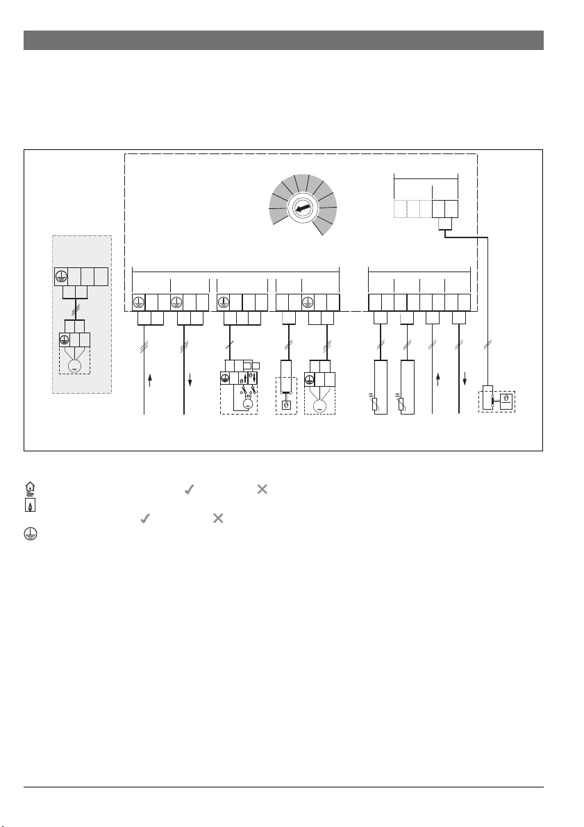
26 | Instalación
0
1
2
3
4
5
6
7
8
9
10
3.3.3 Vista general del estado de ocupación de los bornes
de conexión
Esta vista general muestra qué piezas de la instalación se pueden conectar. Los componentes de la instalación marcados
con * también se pueden utilizar alternativamente. Según el uso
del módulo (codificación en el módulo y configuración a través
VC1
120/230 V AC
N7475
NL
M
PW2*
120/230VAC 120/230VAC
N L N N 43 N 6344 15 16L
230 V AC 230 V AC
4
NMN
VC1
PW2*
43 44
M
del control externo) se conectará uno de los componentes al
borne de conexión (p. ej. “PC1” o “PW1” al borne de conexión
“PC1”). Las piezas de la instalación se deben conectar según se
indica en el esquema de conexiones ( tab. “Esquemas de
conexión con ejemplos de instalaciones”).
MM100
1)
10
≤ 24V
OC131MD1
12 2
≤ 24V
MC1VC1 PC1
PC1
MC1
PW1*
T0 BUS
1212 12
NL
M
TC1
TW1*
BUS
12
BUS BUST0 TC1
MD1
6 720 810 981-01.2O
%-rel
Leyenda sobre la figura superior y sobre la fig. 19 hasta 27, a partir de la pág. 98:
Posible con bomba de calor ( ) o no posible ( )
Posible con otros generadores de calor que no sean
bombas de calor ( ) o no posible ( )
Conductor protector
J Temperatura/sonda de temperatura
L Fase (tensión de red)
N Conductor neutro
Denominaciones de los bornes de conexión:
230 V AC Conexión tensión de red
BUS Conexión sistema de BUS EMS 2
MC1 Controlador de temperatura (Monitor Circuit)
MD1 Contacto libre de potencial (Monitor Dew point):
al enfriar (función de refrigeración): punto de rocío
alcanzado/punto de rocío no alcanzado (%rel)
en circuito de calefacción constante: señal externa
para demanda calorífica () – bomba de calefacción conectada/desconectada ( accesorios adicionales)
T0 Conexión de la sonda de temperatura al compensa-
dor hidráulico o al acumulador de inercia auxiliar
(Temperature sensor)
TC1 Conexión sonda de temperatura de circuito de cale-
facción o sonda de temperatura del acumulador
VC1 Conexión motor mezclador (Valve Circuit):
(Temperature sensor Circuit)
borne de conexión 43: mezclador abierto (en calefacción más caliente; en refrigeración (función de
refrigeración): más frío)
borne de conexión 44:mezclador cerrado (en calefacción más frío; en refrigeración (función de refrigeración): más caliente)
-o-
conexión bomba de recirculación en circuito de
agua caliente (interruptor codificador en 9 o 10):
borne de conexión 43: bomba de recirculación fase
borne de conexión 44: no ocupado
OC1 Sin función
PC1 Conexión bomba (Pump Circuit)
6 720 813 621 (2014/12) MM100
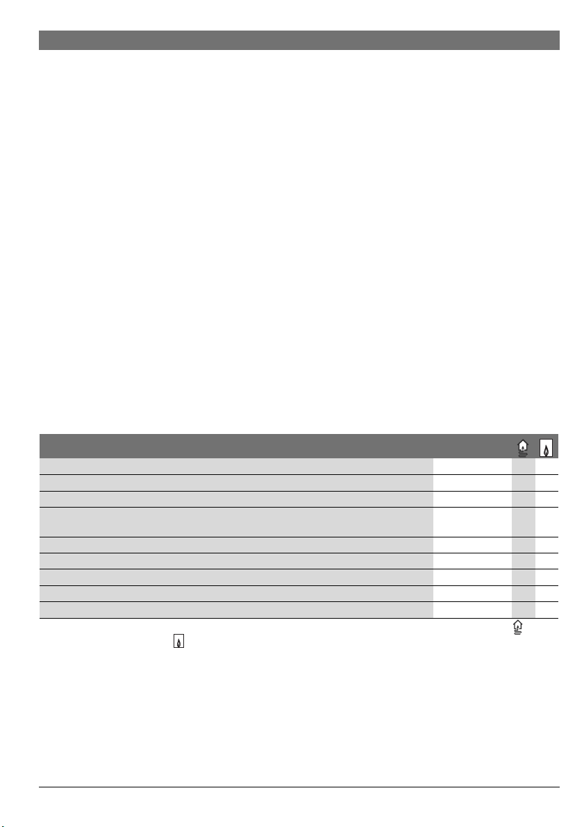
Instalación | 27
Componentes de la instalación:
230 V AC Tensión de red
BT Acumulador de inercia auxiliar (Buf fer Tank)
BUS Sistema de BUS EMS 2/EMS plus
CON Control externo EMS 2/EMS plus (Control)
HS... Generador de calor (Heat Source)
HS1: caldera, p. ej. caldera de pared de condensación a gas
HS2: caldera, p. ej. caldera de condensación a gas
HS3: bomba de calor, p. ej. bomba de calor aire-agua
IC1 Contacto de conmutación para demanda calorífica
externa () en el circuito de calefacción asignado,
accesorios adicionales
MC1 Controlador de temperatura en el circuito de cale-
facción asignado (en circuito de calefacción directo
opcional); si no hay controlador de temperatura,
conectar cable de conexión ( fig. 1 [2], pág. 91)
PC1 Bomba de calefacción del circuito de calefacción
asignado
PW1 Bomba de carga del acumulador en el circuito de
carga del acumulador asignado, p. ej. tras compensador hidráulico (interruptor codificador en 9 o 10)
PW2 Bomba de recirculación en el sistema de agua
caliente asignado (interruptor codificador en 9 o 10)
T0 Sonda de la temperatura de impulsión en el com-
pensador hidráulico o en el acumulador de inercia
auxiliar opcional
TC1 Sonda de temperatura de impulsión en el circuito de
calefacción asignado
TW1 Sonda de temperatura del acumulador en el circuito
de carga del acumulador asignado (interruptor codificador en 9 o 10)
VC1 Moto r mezclador en el circuito de calefacción de
mezcla asignado
al borne de conexión MC1
MD1 Sensor de condensación (%rel) en el circuito de
calefacción asignado, accesorios adicionales
1) Según el control externo instalado un máximo
de 4 u 8
MM100 Modulo MM100
3.3.4 Esquemas de conexiones con ejemplos de instalaciones
Las representaciones hidráulicas solo son esquemáticas y proporcionan un aviso no vinculante sobre un posible ajuste
hidráulico.
▶ Instalar los dispositivos de seguridad según las
normativas y los reglamentos locales.
▶ Consultar en la documentación de planificación o en la
licitación otra información y otras posibilidades.
Función circuito de calefacción Fig./pág.
Mezclado 19 / 98
Calentar/refrigerar 20 / 99 –
Sin mezclar 21 / 100
Circuito de carga del acumulador con bomba de carga del acumulador separada1) y bomba de
22 / 101 –
recirculación
Constante 23 / 102 –
1 sin mezclar, 3 mezclados, 1 circuito de carga del acumulador con caldera 24 / 103 –
1 sin mezclar, 3 mezclados, 1 circuito de carga del acumulador con caldera 25 / 104 –
1 sin mezclar, 3 mezclados, agua de calefacción con bomba de calor 26 / 105 –
1 sin mezclar, 2 o más mezclados, 2 circuitos de carga del acumulador con caldera 27 / 106 –
Tab. 11 Esquemas de conexiones con ejemplos de instalación para el módulo en combinación con la bomba de calor ( ) u otros
generadores de calor ( )
1) p. ej. tras compensador hidráulico
6 720 813 621 (2014/12)MM100
28 | Puesta en marcha
4Puesta en marcha
Asignar circuito de carga del acumulador (1 o 2) mediante la
ruleta codificadora:
¡Conectar correctamente todas las conexiones
eléctricas y, solo entonces, activar la puesta en
marcha!
▶ Tener en cuenta el manual de instalación
de todos los componentes y grupos constructivos de la instalación.
▶ Asegurarse de que no hay varios módulos
con la misma codificación.
▶ Conectar la alimentación de tensión única-
mente cuando todos los módulos estén
ajustados.
AVISO: Tras la puesta en marcha y mientras la
regulación no haya reconocido el módulo, las
bombas conectadas pueden comenzar a funcionar inmediatamente.
▶
Antes de conectar la instalac ión, llenarla
para que las bombas no funcionen en se co.
4.1 Ajustar la ruleta codificadora
Cuando a ruleta codificadora de dirección se encuentre en una
posición válida, el testigo luminoso se iluminará en verde de
forma permanente. Cuando a ruleta codif icadora se encuentra
en una posición no válida o en una posición intermedia, primero el testigo luminoso no se ilumina y a continuación
empieza a parpadear en rojo.
Asignar circuitos de calefacción mediante la ruleta codificadora de direcciones:
Cuando un circuito de calefacción está directamente conectado a un generador de calor, la ruleta codificadora de direcciones no puede
colocarse en la posición 1 en ningún módulo.
El primer circuito de calefacción detrás del compensador hidráulico es en este caso el circuito de
calefacción 2.
• 1 circuito de calefacción:
ruleta codificadora en 1
• 2 circuitos de calefacción:
circuito de calefacción 1 = ruleta codificadora en 1;
circuito de calefacción 2 = ruleta codificadora en 2
• 3 circuitos de calefacción:
circuito de calefacción 1 = ruleta codificadora en 1;
circuito de calefacción 2 = ruleta codificadora en 2;
circuito de calefacción 3 = ruleta codificadora en 3 etc.
Cuando un circuito de carga del acumulador
está directamente conectado a un generador
de calor, la ruleta codificadora de direcciones
no puede colocarse en la posición 9 en ningún
módulo. El circuito de carga del acumulador
detrás del compensador hidráulico es en este
caso el circuito de carga del acumulador 2.
• 1 circuito de carga del acumulador: interruptor codificador
en 9
• 2 circuitos de carga del acumulador:
circuito de carga del acumulador 1 = interruptor codificador en 9;
circuito de carga del acumulador 2 = interruptor codificador en 10
4.2 Puesta en marcha de la instalación y del
módulo
4.2.1 Ajustes para circuito de calefacción
1. Asignar el módulo a un circuito de calefacción (según el
control externo instalado 1... 8).
2. En su caso, ajustar la rule ta codificadora en otros módulos.
3. Conectar adicionalmente la tensión de red de toda la instalación.
Cuando el testigo luminoso del módulo se ilumina en verde de
forma permanente:
4. Poner en marcha el control externo según el manual de instalación incluido y ajustarlo como corresponda.
4.2.2 Ajustes para el circuito de carga del acumulador
1. Asignar el módulo a un circuito de carga del acumulador
(9 ... 10).
2. En su caso, ajustar el interruptor codificador en otros
módulos.
3. Conectar adicionalmente la tensión de red de toda la instalación.
Cuando el testigo luminoso del módulo se ilumina en verde de
forma permanente:
4. Poner en marcha el control externo según el manual de instalación incluido y ajustarlo como corresponda.
6 720 813 621 (2014/12) MM100
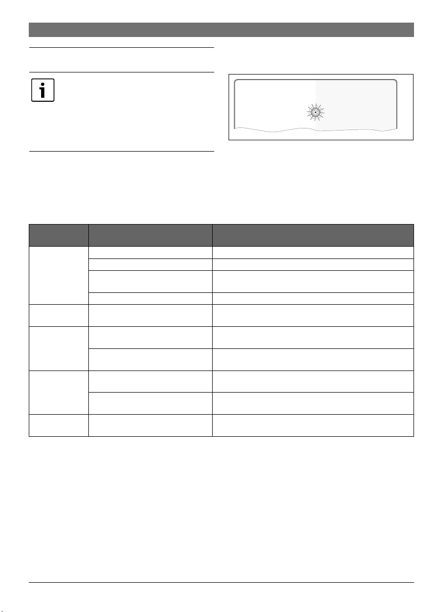
5 Subsanación de las averías
0
1
2
3
4
5
6
7
8
9
10
6 720 645 409-20.1o
Utilizar únicamente piezas de repuesto originales.
Los daños provocados por piezas de repuesto no
suministradas por el fabricante no se incluyen en
la garantía.
Si una avería no puede subsanarse, póngase en
contacto con el técnico de servicio correspondiente.
Indicación de
servicio
apagado de forma
permanente
en rojo de forma
permanente
rojo parpadeando Interruptor codificador en posición no
verde
parpadeando
verde de forma
permanente
Tab. 12
Causas posibles Remedio
Interruptor codificador en 0 ▶ Ajustar el interruptor codificador.
Alimentación de tensión interrumpida. ▶ Conectar la alimentación de tensión.
Fusible defectuoso ▶ En caso de alimentación de tensión desconectada, cambiar el
Cortocircuito en la conexión de BUS ▶ Comprobar la conexión BUS y reparar en caso necesario.
Avería interna ▶ Sustituir el módulo.
válida o en posición intermedia
El limitador de temperatura en MC1
(15-16) no está conectado
Se ha superado la longitud máxima del
cable de la conexión BUS
indicador de avería en el display del
control externo
No existe avería Funcionamiento normal
Subsanación de las averías | 29
La indicación de funcionamiento muestra el estado de funcionamiento del módulo.
Si surge una avería en el módulo, el mezclador del circuito de
calefacción mezclado conectado se coloca en una posición
determinada por el módulo. De este modo es posible seguir
operando la instalación con potencia calorífica reducida.
Algunas averías también se muestran en el display del control
externo asignado al circuito de calefacción y en su caso subordinado a este.
fusible ( fig. 16, pág. 96).
▶ Ajustar el interruptor codificador.
▶ Conectar tubo de conexión o limitador de temperatura al MC1.
▶ Establecer una conexión BUS más corta.
▶ Las instrucciones del control externo y el manual de servicio
contienen otros avisos sobre la eliminación de fallos.
6 720 813 621 (2014/12)MM100

30 | Protección del medio ambiente/reciclaje
6 Protección del medio ambiente/reciclaje
La protección del medio ambiente es uno de los principios
empresariales del Grupo Bosch.
La calidad de los productos, la rentabilidad y la protección del
medio ambiente tienen para nosotros la misma importancia.
Las leyes y normativas para la protección del medio ambiente
se respetan rigurosamente.
Para proteger el medio ambiente, utilizamos las tecnologías y
materiales más adecuados, teniendo en cuenta también los
aspectos económicos.
Embalaje
En cuanto al embalaje, nos implicamos en los sistemas de reutilización específicos de cada región para garantizar un reciclaje óptimo.
Todos los materiales del embalaje son respetuosos con el
medio ambiente y reutilizables.
Aparatos usados eléctricos y electrónicos
Los aparatos eléctricos y electrónicos inservibles deben separarse para su eliminación y
reutilizarlos de acuerdo con el medio
ambiente (Directiva Europea de Residuos de
aparatos eléctricos y electrónicos).
Utilice los sistemas de restitución y colecta
para la eliminación de residuos de aparatos
eléctricos y electrónicos.
6 720 813 621 (2014/12) MM100
 Loading...