


MIC-7130-PB4
Bosch MIC-7130-PB4, MIC-7230-W5, MIC-7230-G5, MIC-7130-PW4, MIC-7130-PG4 Operation Manual
...
MIC IP starlight 7000 HD
MIC-7130-PB4 │ MIC-7130-PW4 │ MIC-7130-PG4 │ MIC-7230-B5
│ MIC-7230-W5 │ MIC-7230-G5
en
Operation Manual


MIC IP starlight 7000 HD Table of contents | en 3
Bosch Security Systems Operation Manual 2016.07 | 5.0 | F.01U.291.520
Table of contents
1
Safety 6
1.1 About this Manual 6
1.2 Legal Information 6
1.3 Safety Precautions 6
1.4 Important Safety Instructions 7
1.5 Important Notices 7
1.6 Important Notices - Illumination Safety 10
1.7 Customer Support and Service 12
2
Unpacking 13
2.1 Parts List - Camera 13
2.2 Additional Tools 13
3
Product Description 14
4
Overview of Installation Steps 15
5
Configuration Programming in the Shipping Box 17
6
Configuration Programming on a Temporary Table-top Stand 18
7
Mounting Location and Mounting Orientation 19
7.1 Select the Mounting Location 19
7.2 Select the Mounting Orientation 20
8
Overview of Mounting Options 22
9
Install the Camera 25
10
Make Connections - Power and Control 26
10.1 About Camera Power and Control 26
10.2 Power Source Options 26
10.3 Ethernet Connections 27
10.4 Camera Connections 28
10.5 Connect the Camera to the Network 29
11
Cant the Camera 30
12
Typical System Configurations 36
12.1 Typical IP Configuration with 95 W midspan (no I/O connections) 36
12.2 Typical Configuration with MIC-ALM-WAS-24 37
12.3 Typical IP Configuration with VJC-7000-90 38
13
Configuration 39
13.1 System Requirements 39
13.2 Configuring the Camera 39
13.2.1 Using the Configuration Manager 40
13.2.2 Using the Web Server of the Camera 40
13.2.3 About the Configuration Page 41
13.3 Configuring Audio (Optional) 41
14
General 42
14.1 Identification 42
14.2 User Management 42
14.3 Date/Time 43
14.4 Display Stamping 44
14.5 GB/T 28181 46
15
Web Interface 47
15.1 Appearance 47
15.2 LIVE Functions 48
16
Camera 50

4 en | Table of contents MIC IP starlight 7000 HD
2016.07 | 5.0 | F.01U.291.520 Operation Manual Bosch Security Systems
16.1 Installer Menu 50
16.1.1 Positioning 50
16.2 Encoder Profile 51
16.3 Encoder Streams 53
16.4 Encoder Regions 55
16.5 Privacy Masks 56
16.6 Picture Settings 57
16.7 Lens Settings 59
16.8 PTZ Settings 60
16.9 Prepositions and Tours 62
16.10 Preposition mapping 63
16.11 Sectors 64
16.12 Miscellaneous 65
16.13 Illumination/Wiper 65
16.14 Audio 66
16.15 Pixel Counter 66
16.16 Pelco AUX map 66
17
Recording 68
17.1 Storage Management 68
17.1.1 Device manager 68
17.1.2 Recording media 68
17.1.3 Activating and configuring storage media 68
17.1.4 Formatting storage media 69
17.1.5 Deactivating storage media 69
17.2 Recording Profiles 69
17.3 Maximum Retention Time 71
17.4 Recording Scheduler 71
17.5 Recording Status 72
18
Alarm 73
18.1 Alarm Connections 73
18.2 VCA 75
18.3 Virtual Masks 79
18.4 Audio Alarm 79
18.5 Alarm E-Mail 80
18.6 Alarm Task Editor 81
18.7 Alarm Rules 81
19
Interfaces 83
19.1 Alarm Inputs 83
19.2 Alarm Outputs 83
20
Network 84
20.1 Network Access 84
20.2 DynDNS 86
20.3 Advanced 86
20.4 Network Management 87
20.5 Multicast 88
20.6 Image Posting 89
20.7 Accounts 90
20.8 IPv4 Filter 91
21
Service 92

MIC IP starlight 7000 HD Table of contents | en 5
Bosch Security Systems Operation Manual 2016.07 | 5.0 | F.01U.291.520
21.1 Maintenance 92
21.2 Licenses 92
21.3 Certificates 92
21.4 Diagnostics 93
21.5 System Overview 93
22
Operation via the browser 95
22.1 Live page 95
22.1.1 Prepositions 95
22.1.2 AUX Control 96
22.1.3 Intelligent Tracking 96
22.1.4 Special Functions 96
22.1.5 Recording status 96
22.1.6 Saving snapshots 97
22.1.7 Recording live video 97
22.1.8 Full-screen display 97
22.1.9 Audio communication 97
22.1.10 Storage, CPU and network status 97
22.2 Playback 98
22.2.1 Selecting the recording stream 98
22.2.2 Searching for recorded video 98
22.2.3 Exporting recorded video 98
22.2.4 Controlling playback 98
23
Operation 99
23.1 Using Intelligent Tracking 99
23.2 Recommended Use of Your MIC Camera 102
23.3 Using the Wiper/Washer (Bosch Protocol) 103
23.4 Using the Wiper/Washer (Pelco Protocol) 104
23.5 Configuring Settings for IR Illumination 105
23.6 Uploading a User Logo 105
23.7 Two-line and Three-line Camera Titles 106
23.8 Azimuth, Elevation, and Compass Directions 108
24
Troubleshooting 109
25
Maintenance 112
26
Decommissioning 113
26.1 Transfer 113
26.2 Disposal 113
27
Technical data 114
28
Keyboard Commands 115
28.1 Bosch Protocol 115
28.2 Pelco Protocol 119
6 en | Safety MIC IP starlight 7000 HD
2016.07 | 5.0 | F.01U.291.520 Operation Manual Bosch Security Systems
1 Safety
1.1 About this Manual
This manual has been compiled with great care and the information it contains has been
thoroughly verified. The text was complete and correct at the time of printing. Because of the
ongoing development of products, the content of the manual may change without notice.
Bosch Security Systems accepts no liability for damage resulting directly or indirectly from
faults, incompleteness, or discrepancies between the manual and the product described.
1.2 Legal Information
Copyright
This manual is the intellectual property of Bosch Security Systems, Inc. and is protected by
copyright. All rights reserved.
Trademarks
All hardware and software product names used in this document are likely to be registered
trademarks and must be treated accordingly.
1.3 Safety Precautions
In this manual, the following symbols and notations are used to draw attention to special
situations:
Danger!
High risk: This symbol indicates an imminently hazardous situation such as “Dangerous
Voltage” inside the product. If not avoided, this will result in an electrical shock, serious
bodily injury, or death.
!
Warning!
Medium risk: Indicates a potentially hazardous situation. If not avoided, this may result in
minor or moderate injury.
!
Caution!
Low risk: Indicates a potentially hazardous situation. If not avoided, this may result in
property damage or risk of damage to the unit.
Notice!
This symbol indicates information or a company policy that relates directly or indirectly to the
safety of personnel or protection of property.
MIC IP starlight 7000 HD Safety | en 7
Bosch Security Systems Operation Manual 2016.07 | 5.0 | F.01U.291.520
1.4 Important Safety Instructions
Read, follow, and retain all of the following safety instructions. Heed all warnings on the unit
and in the operating instructions before operation.
!
Caution!
TO REDUCE THE RISK OF ELECTRIC SHOCK, DISCONNECT THE POWER SOURCE WHILE
INSTALLING THE DEVICE.
!
Caution!
Installation must be made by qualified personnel and conform to ANSI/NFPA 70 (the National
Electrical Code® (NEC)), Canadian Electrical Code, Part I (also called CE Code or CSA C22.1),
and all applicable local codes. Bosch Security Systems, Inc. accepts no liability for any
damages or losses caused by incorrect or improper installation.
!
Warning!
ROUTING OF EXTERNAL WIRING MUST BE DONE THROUGH A PERMANENTLY EARTHED
METAL CONDUIT.
!
Warning!
THE CAMERA MUST BE MOUNTED DIRECTLY AND PERMANENTLY TO A NON-COMBUSTIBLE
SURFACE.
– Do not place a canted (45°) camera upright; it can fall over easily. Place the canted
camera on its side.
– Do not open the camera unit. Doing so will invalidate the warranty.
Use common-sense safety precautions, especially in situations where there could be risk of
injury if any part of the assembly becomes detached and falls. Bosch recommends using the
hinged DCA, which allows installers to “hang” the MIC camera temporarily on the DCA to
make electrical connections, before bolting the camera to the DCA.
– Ensure that the unit case is properly earthed. If the product is likely to be struck by
lightning, ensure that earth bonding connections are made correctly to the mounting of
the base of the unit.
– Do not point the camera at the sun. Bosch Security Systems will not be liable for any
damage to cameras that have been pointed directly at the sun.
– Before transporting, supply power to the camera and rotate the ball so that the window
points toward the base. This will help to protect the wiper and the window during transit.
!
Warning!
Moving parts!
Moving parts may result in risk of injury, therefore, the device should be mounted so that it is
accessible only to the technician/installer.
1.5 Important Notices
Notice!
This device is intended for use in public areas only.
U.S. federal law strictly prohibits surreptitious recording of oral communications.

8 en | Safety MIC IP starlight 7000 HD
2016.07 | 5.0 | F.01U.291.520 Operation Manual Bosch Security Systems
Accessories - Do not place this unit on an unstable stand, tripod, bracket, or
mount. The unit may fall, causing serious injury and/or serious damage to
the unit. Use only with mounting solutions specified by the manufacturer.
When a cart is used, use caution and care when moving the cart/unit
combination to avoid injury from tip-over. Quick stops, excessive force, or
uneven surfaces may cause the cart/unit combination to overturn. Mount the
unit per the installation instructions.
Adjustment of controls - Adjust only those controls specified in the operating instructions.
Improper adjustment of other controls may cause damage to the unit.
All-pole power switch - Incorporate an all-pole power switch, with a contact separation of at
least 3 mm in each pole, into the electrical installation of the building.If it is needed to open
the housing for servicing and/or other activities, use this all-pole switch as the main
disconnect device for switching off the voltage to the unit.
Camera signal - Protect the cable with a primary protector if the camera signal is beyond 140
feet, in accordance with NEC800 (CEC Section 60).
Environmental statement - Bosch has a strong commitment towards the environment. This
unit has been designed to respect the environment as much as possible.
Electrostatic-sensitive device - Use proper CMOS/MOS-FET handling precautions to avoid
electrostatic discharge. NOTE: Wear required grounded wrist straps and observe proper ESD
safety precautions when handling the electrostatic-sensitive printed circuit boards.
Fuse rating - For security protection of the device, the branch circuit protection must be
secured with a maximum fuse rating of 16A. This must be in accordance with NEC800 (CEC
Section 60).
Grounding:
- Connect outdoor equipment to the unit's inputs only after this unit has had its ground
terminal connected properly to a ground source.
- Disconnect the unit's input connectors from outdoor equipment before disconnecting the
grounding terminal.
- Follow proper safety precautions such as grounding for any outdoor device connected to this
unit.
U.S.A. models only - Section 810 of the National Electrical Code, ANSI/NFPA No.70, provides
information regarding proper grounding of the mount and supporting structure, size of
grounding conductors, location of discharge unit, connection to grounding electrodes, and
requirements for the grounding electrode.
Heat sources - Do not install unit near any heat sources such as radiators, heaters, or other
equipment (including amplifiers) that produce heat.
Moving - Disconnect the power before moving the unit. Move the unit with care. Excessive
force or shock may damage the unit.
Outdoor signals - The installation for outdoor signals, especially regarding clearance from
power and lightning conductors and transient protection, must be in accordance with NEC725
and NEC800 (CEC Rule 16-224 and CEC Section 60).
Permanently connected equipment - Incorporate a readily accessible disconnect device in the
building installation wiring.
Power lines - Do not locate the camera near overhead power lines, power circuits, or
electrical lights, nor where it may contact such power lines, circuits, or lights.
Damage requiring service – Unplug the devices from the main AC power source and refer
servicing to qualified service personnel whenever any damage to the device has occurred,
such as:
- the power supply cable is damaged;

MIC IP starlight 7000 HD Safety | en 9
Bosch Security Systems Operation Manual 2016.07 | 5.0 | F.01U.291.520
- an object has fallen on the device;
- the device has been dropped, or its enclosure has been damaged;
- the device does not operate normally when the user follows the operating instructions
correctly.
Servicing - Do not attempt to service this device yourself. Refer all servicing to qualified
service personnel.
This device has no user-serviceable internal parts.
Notice!
This is a class A product. In a domestic environment this product may cause radio
interference, in which case the user may be required to take adequate measures.
Notice!
Ce produit est un appareil de Classe A. Son utilisation dans une zone résidentielle risque de
provoquer des interférences. Le cas échéant, l’utilisateur devra prendre les mesures
nécessaires pour y remédier.
FCC & ICES Information
(U.S.A. and Canadian Models Only)
This device complies with part 15 of the FCC Rules. Operation is subject to the following
conditions:
– this device may not cause harmful interference, and
– this device must accept any interference received, including interference that may cause
undesired operation.
NOTE: This equipment has been tested and found to comply with the limits for a Class A
digital device, pursuant to Part 15 of the FCC Rules and ICES-003 of Industry Canada. These
limits are designed to provide reasonable protection against harmful interference when the
equipment is operated in a commercial environment. This equipment generates, uses, and
radiates radio frequency energy and, if not installed and used in accordance with the
instruction manual, may cause harmful interference to radio communications. Operation of
this equipment in a residential area is likely to cause harmful interference, in which case the
user will be required to correct the interference at his expense.
Intentional or unintentional modifications, not expressly approved by the party responsible for
compliance, shall not be made. Any such modifications could void the user's authority to
operate the equipment. If necessary, the user should consult the dealer or an experienced
radio/television technician for corrective action.
The user may find the following booklet, prepared by the Federal Communications
Commission, helpful: How to Identify and Resolve Radio-TV Interference Problems. This
booklet is available from the U.S. Government Printing Office, Washington, DC 20402, Stock
No. 004-000-00345-4.
Informations FCC et ICES
(modèles utilisés aux États-Unis et au Canada uniquement)
Ce produit est conforme aux normes FCC partie 15. la mise en service est soumises aux deux
conditions suivantes :
– cet appareil ne peut pas provoquer d'interférence nuisible et
– cet appareil doit pouvoir tolérer toutes les interférences auxquelles il est soumit, y
compris les interférences qui pourraient influer sur son bon fonctionnement.
10 en | Safety MIC IP starlight 7000 HD
2016.07 | 5.0 | F.01U.291.520 Operation Manual Bosch Security Systems
AVERTISSEMENT: Suite à différents tests, cet appareil s’est révélé conforme aux exigences
imposées aux appareils numériques de Classe A en vertu de la section 15 du règlement de la
Commission fédérale des communications des États-Unis (FCC). Ces contraintes sont
destinées à fournir une protection raisonnable contre les interférences nuisibles quand
l'appareil est utilisé dans une installation commerciale. Cette appareil génère, utilise et émet
de l'energie de fréquence radio, et peut, en cas d'installation ou d'utilisation non conforme aux
instructions, générer des interférences nuisibles aux communications radio. L’utilisation de ce
produit dans une zone résidentielle peut provoquer des interférences nuisibles. Le cas
échéant, l’utilisateur devra remédier à ces interférences à ses propres frais.
Au besoin, l’utilisateur consultera son revendeur ou un technicien qualifié en radio/télévision,
qui procédera à une opération corrective. La brochure suivante, publiée par la Commission
fédérale des communications (FCC), peut s’avérer utile : How to Identify and Resolve Radio-TV
Interference Problems (Comment identifier et résoudre les problèmes d’interférences de radio
et de télévision). Cette brochure est disponible auprès du U.S. Government Printing Office,
Washington, DC 20402, États-Unis, sous la référence n° 004-000-00345-4.
UL Disclaimer
Underwriter Laboratories Inc. ("UL") has not tested the performance or reliability of the
security or signaling aspects of this product. UL has only tested fire, shock and/or casualty
hazards as outlined in Standard(s) for Safety for Information Technology Equipment, UL
60950-1 . UL Certification does not cover the performance or reliability of the security or
signaling aspects of this product.
UL MAKES NO REPRESENTATIONS, WARRANTIES, OR CERTIFICATIONS WHATSOEVER
REGARDING THE PERFORMANCE OR RELIABILITY OF ANY SECURITY OR SIGNALING-RELATED
FUNCTIONS OF THIS PRODUCT.
1.6 Important Notices - Illumination Safety
The text in this section applies only to cameras which have the optional illuminator accessory.
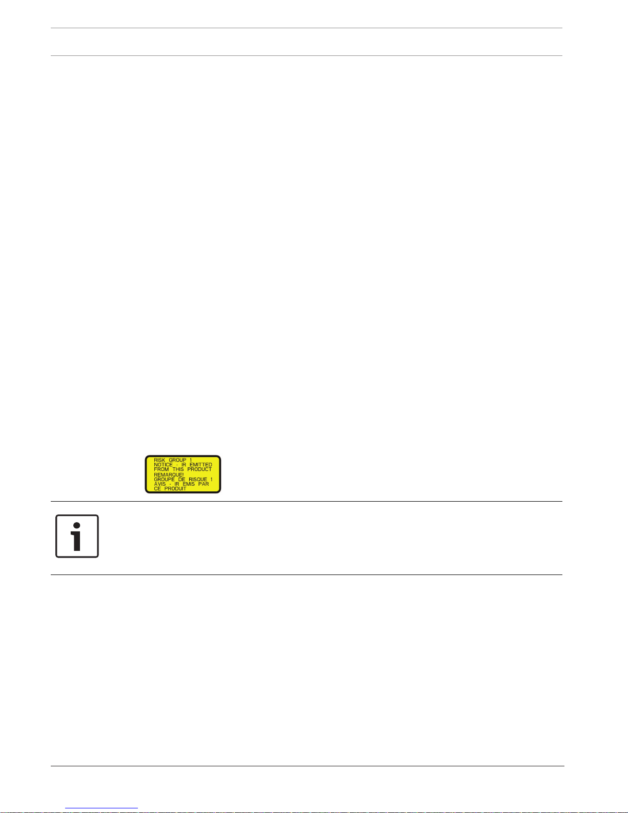
Notice!
This product has been tested according to standard IEC62471:2006 “Photobiological safety
of lamps and lamp systems”. The product emissions exceed the EXEMPT Group limit for both
Retinal Blue Light and Cornea/Lens infrared hazard as defined by IEC 62471:2006. The
product was found to meet the Risk Group 1 exposure limits for IR and White LEDs.
The IEC 62471 provides the methods to determine the risk group of any lamp or any product
incorporating a lamp. The risk groups in IEC 62471 indicate the degree of risk from potential
optical radiation hazards. The risk groups were developed based upon decades of lamp use
experience and the analysis of accidental injuries related to optical radiation emission.
EXEMPT Group – no optical hazard is considered reasonably foreseeable, even for
continuous, unrestricted use. Typical examples are most frosted incandescent lamps and
fluorescent lamps used in domestic applications.
Risk Group 1 – products are safe for most use applications, except for very prolonged
exposures where direct ocular exposures may be expected. An example of Risk Group 1 is a
domestic battery operated torch (flashlight).

MIC IP starlight 7000 HD Safety | en 11
Bosch Security Systems Operation Manual 2016.07 | 5.0 | F.01U.291.520
Exposure Hazard Value (EHV) is a ratio of the Exposure Level (distance, exposure time) to
Exposure Limit Value (ELV). When EHV is greater than 1, the device has exceeded the
Exposure Limit Values for a particular Risk Group. The ELV is the level where optical radiation
to the eye or skin is not expected to result in adverse biological effects.
The Hazard Distance (HD) is the distance from the source at which the Exposure Level equals
the appropriate ELV. In other words, when EHV=1 for a particular Risk Group.
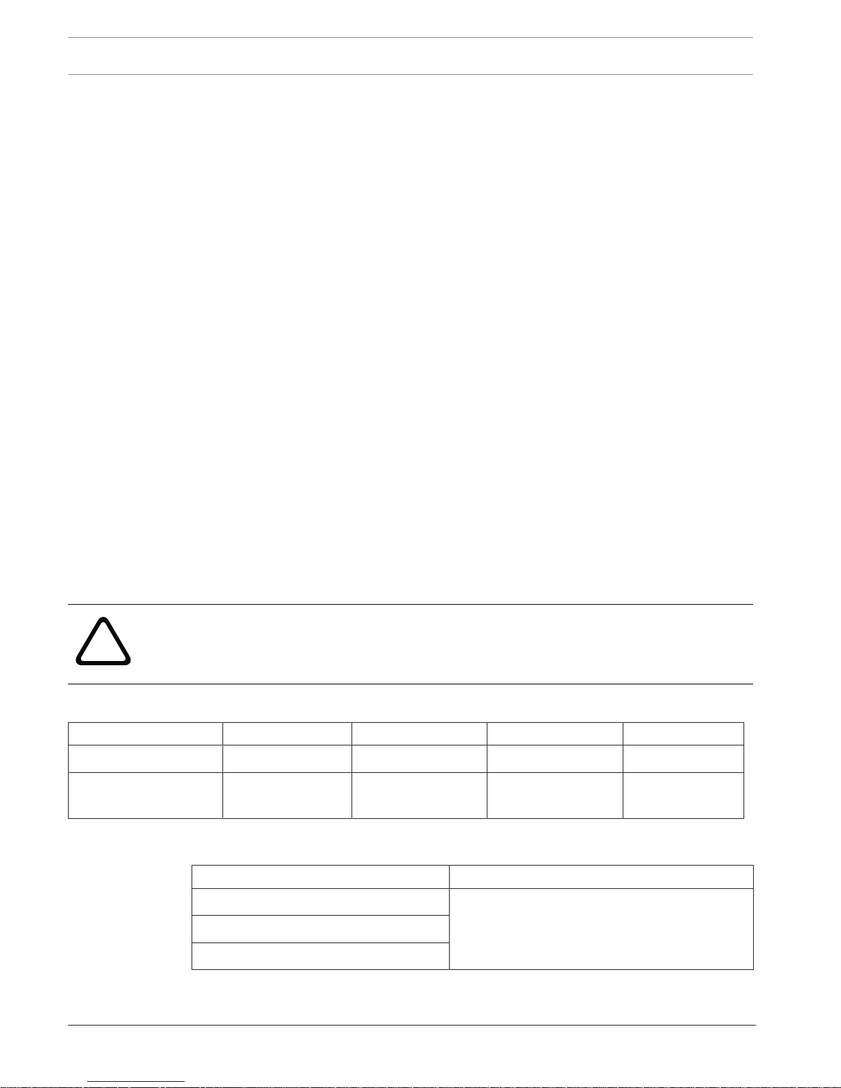
Regarding the Cornea / Lens infrared hazard of this product, the Exposure Hazard Value (EHV)
at a test distance of 200mm is 2.19 based on EXEMPT Group exposure limits. The EHV based
on Risk Group 1 limits is 0.386. The HD for the Exempt Group is 297 mm.
Regarding the Retinal Blue Light hazard, the EHV is 22.9 based on the EXEMPT Group
exposure limits and a test distance of 200 mm. The EHV based on Risk Group 1 limits is 0.266.
The HD for the Exempt Group is 2675 mm.
These values have been summarized in the table below:
Hazard
EXEMPT Group Limits Risk Group 1 Limits
t, duration d, distance EHV t, duration d, distance EHV
Cornea / Lens
Infrared Hazard
1000 s
Hazard
Distance
200 mm
279 mm
2.19 100 s 200 mm 0.386
Retinal Blue Light
Hazard
10,000 s
Hazard
Distance
200 mm
2675 mm
22.9 100s 200 mm 0.266

12 en | Safety MIC IP starlight 7000 HD
2016.07 | 5.0 | F.01U.291.520 Operation Manual Bosch Security Systems
1.7 Customer Support and Service
If this unit needs service, contact the nearest Bosch Security Systems Service Center for
authorization to return and shipping instructions.
Service Centers
USA
Telephone: 800-366-2283 or 585-340-4162
Fax: 800-366-1329
Email: cctv.repair@us.bosch.com
Customer Service
Telephone: 888-289-0096
Fax: 585-223-9180
Email: security.sales@us.bosch.com
Technical Support
Telephone: 800-326-1450
Fax: 585-223-3508 or 717-735-6560
Email: technical.support@us.bosch.com
Repair Center
Telephone: 585-421-4220
Fax: 585-223-9180 or 717-735-6561
Email: security.repair@us.bosch.com
Canada
Telephone: 514-738-2434
Fax: 514-738-8480
Europe, Middle East & Africa Region
Please contact your local distributor or Bosch sales office. Use this link:
http://www.boschsecurity.com/startpage/html/europe.htm
Asia Pacific Region
Please contact your local distributor or Bosch sales office. Use this link:
http://www.boschsecurity.com/startpage/html/asia_pacific.htm
More Information
For more information please contact the nearest Bosch Security Systems location or visit
www.boschsecurity.com
MIC IP starlight 7000 HD Unpacking | en 13
Bosch Security Systems Operation Manual 2016.07 | 5.0 | F.01U.291.520
2 Unpacking
– This equipment should be unpacked and handled with care. Check the exterior of the
packaging for visible damage. If an item appears to have been damaged in shipment,
notify the shipper immediately.
– Verify that all the parts listed in the Parts List below are included. If any items are
missing, notify your Bosch Security Systems Sales or Customer Service Representative.
– Do not use this product if any component appears to be damaged. Please contact Bosch
Security Systems in the event of damaged goods.
– The original packing carton is the safest container in which to transport the unit and must
be used if returning the unit for service. Save it for possible future use.
MIC7000 packaging is designed:
– to allow installers to configure the camera inside the shipping box.
– to provide a temporary table-top or desk-top stand.
!
Caution!
Take extra care lifting or moving MIC7000 cameras because of their weight (6.7 kg (14.7 lb)).
2.1 Parts List - Camera
One (1) MIC IP starlight 7000 HD Camera
One (1) Quick Installation Guide
One (1) spanner tool [to remove and to attach the yoke caps in order to cant the camera if desired,
and to remove the access plug from the camera head when installing the optional illuminator
accessory (sold separately)]
One (1) base gasket
One (1) RJ45 coupler
Four (4) MAC address labels
One (1) ground screw
2.2 Additional Tools
The following table lists additional tools (not supplied by Bosch) that may be required to
install a MIC camera or its accessories:
1 Phillips-head screwdriver to secure the ground lug of the camera
1 Adjustable wrench or socket set to secure the base of the camera to mounting accessories
1 Torque wrench with 1/4 in. drive to use the supplied spanner tool for removing yoke caps and
blanking plugs if necessary
For canting cameras with Hex head screws:
1 Torque wrench with a 5 mm Hex bit (or T30 Torx bit) to remove/install bolts in the yoke arms
For canting cameras with Torx head screws:
1 Torque wrench with a Torx bit (T30 or T27) to remove/install bolts in the yoke arms

14 en | Product Description MIC IP starlight 7000 HD
2016.07 | 5.0 | F.01U.291.520 Operation Manual Bosch Security Systems
3 Product Description
The MIC7000 camera is a high-performance, weatherproof, ruggedized, fully functional day/
night PTZ camera that has been designed to offer a reliable, robust, and high-quality
surveillance solution for extreme security applications.
Image control and quality are integral aspects of any PTZ camera, and the MIC7000 camera
delivers outstanding clarity and image detail. The camera has a professional-grade imaging
platform capable of delivering HD resolution (720p50/60 for 7130 models or maximum
1080p25/30 for 7230 models) in environments with ambient light extremes.
The camera also has a 30x optical zoom (12x digital) and flexible, field-selectable mounting
orientations (upright, inverted, or canted) to achieve the perfect field of view.
A long-life silicone wiper blade mounted on a spring-loaded arm is standard on all MIC
cameras.
The following table identifies the optional accessories for MIC cameras. Refer to the
datasheets of each accessory for details. Some accessories may not be available in all regions.
Accessories Description Accessories Description
MIC-DCA-H
- MIC-DCA-HB
- MIC-DCA-HW
- MIC-DCA-HG
Hinged Deep Conduit Adapter in
Black
White
Grey
MIC-SCA
- MIC-SCA-BD
- MIC-SCA-WD
- MIC-SCA-GD
Shallow Conduit Adapter in
Black
White
Grey
MIC-CMB
- MIC-CMB-BD
- MIC-CMB-WD
- MIC-CMB-GD
Corner Mount Bracket in
Black
White
Grey
MIC-SPR
- MIC-SPR-BD
- MIC-SPR-WD
- MIC-SPR-GD
Spreader Plate in
Black
White
Grey
MIC-WMB
- MIC-WMB-BD
- MIC-WMB-WD
- MIC-WMB-GD
Wall Mount Bracket in
Black
White
Grey
MIC-ILx-100
- MIC-ILB-100
- MIC-ILW-100
- MIC-ILG-100
User-installable illuminator accessory
designed specifically for MIC7000
cameras, in
Black
White
Grey
MIC-PMB Pole Mount Bracket (stainless
steel only)
MICIP67-5PK MIC7000 IP67 Connector Kit
VJC-7000-90 VIDEOJET connect (Full-featured
network interface unit/power
supply)
NPD-6001A 60 W midspan [Not for use with the
illuminator accessory.]
VG4-A-PSU1, VG4A-PSU2
24 VAC (96 W) power supply NPD-9501A 95 W midspan
MIC-ALM-WAS-24 Alarm and washer interface
accessory unit
MIC-67SUNSHLD Sunshield (white only)

MIC IP starlight 7000 HD Overview of Installation Steps | en 15
Bosch Security Systems Operation Manual 2016.07 | 5.0 | F.01U.291.520
4 Overview of Installation Steps
To install your MIC camera, follow these steps in sequence.
Note: Depending on your model of camera, your desired mounting location and orientation, as
well as your mounting brackets and chosen camera accessories, you may not need to
complete every step.
Determine system
configuration.
Operate the camera.
(Refer to Section 16.)
Connect network cable
(Refer to Section 10.)
Install
illuminator.
Install
sunshield.
Configure settings.
(Refer to Section 13.)
Alarm/Washer
Interface Unit
VIDEOJET connect
PSU
Cant the camera.
(Refer to Section 11.)
Install cabling between power
source and camera mounting site.
Install MIC Camera.
(Refer to Section 9.)
Power supply source
or PoE device
Connect and configure
camera in box or
on table-top stand.
(Refer to Sections 5 & 6.)
Install optional accessories.
(Refer to individual installation manuals.)
Select mounting
location and
orientation.
(Refer to Section 7.)
Install mounting
accessories and
conduit (if applicable).
Identify required
mounting accessories.
(Refer to Section 8.)
Identify Mounting Site Requirements.
Install a
sunshield?
YES
YES
NO
NO
Will
camera
be canted?
Pre-
configure
camera?
NO
YES
YES
NO
Install
optional
camera
access-
ories?
16 en | Overview of Installation Steps MIC IP starlight 7000 HD
2016.07 | 5.0 | F.01U.291.520 Operation Manual Bosch Security Systems
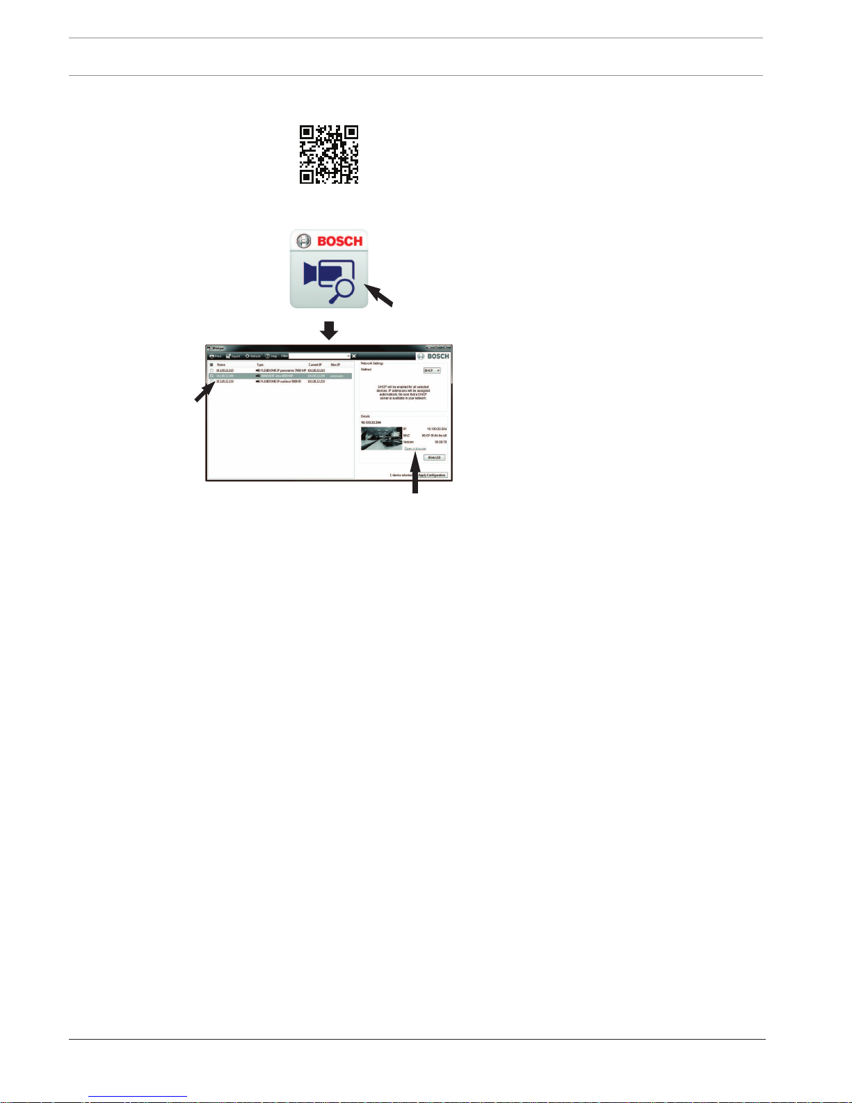
IPHelper
http://downloadstore.boschsecurity.com/
MIC IP starlight 7000 HD Configuration Programming in the Shipping Box | en 17
Bosch Security Systems Operation Manual 2016.07 | 5.0 | F.01U.291.520
5 Configuration Programming in the Shipping Box
!
Caution!
Take extra care lifting or moving MIC7000 cameras because of their weight (6.7 kg (14.7 lb)).
The camera packaging allows installers to connect the camera to the network and configure
the camera still in the box.
1. Remove the accessories box from the top, middle section of the box.
2. Supply power to the camera and Connect the Camera to the Network, page 29. Note that
the wiper moves one time across the camera window, and then returns to parked position.
3. Configure the camera. Refer to Configuration, page 39 for details.
Note: Do not change the camera orientation to “Inverted” while the camera is still in the box.
The camera head must be free to rotate. If you must change the camera’s orientation to
“Inverted,” remove the camera from the box and configure it by following the steps in
Configuration Programming on a Temporary Table-top Stand, page 18.
4. Disconnect the wires/cables from the connectors in the base of the camera.
18 en | Configuration Programming on a Temporary Table-top Stand MIC IP starlight 7000 HD
2016.07 | 5.0 | F.01U.291.520 Operation Manual Bosch Security Systems
6 Configuration Programming on a Temporary Table-top
Stand
The camera (still in the foam) can stand temporarily on a flat, horizontal surface such as a
desk or a table during initial network connection and configuration.
1. Remove the accessories box from the top, middle section of the box.
2. Remove the camera, still in the foam, from the box. Place the camera upright on a flat,
horizontal surface.
3. Remove the foam covering the head of the camera.
4. Supply power to the camera and Connect the Camera to the Network, page 29. Note that
the wiper moves one time across the camera window, and then returns to parked position.
5. Configure the camera. Refer to Configuration, page 39 for details.
Notice!
If you change the camera orientation to “Inverted” (from the Settings page of the web
browser: Advanced > Camera > Installer Menu > Orientation), then the camera head will
rotate automatically into inverted position (180°). Note that the visor will be near the top of
the body of the camera.
6. Disconnect the wires/cables from the connectors in the base of the camera.
MIC IP starlight 7000 HD Mounting Location and Mounting Orientation | en 19
Bosch Security Systems Operation Manual 2016.07 | 5.0 | F.01U.291.520
7 Mounting Location and Mounting Orientation
7.1 Select the Mounting Location
MIC cameras are designed for easy installation in various locations such as directly onto
buildings and poles suitable to support CCTV equipment.
Select a secure installation location and mounting position for the device. Ideally, this is a
location where the device cannot be interfered with either intentionally or accidentally.
Ensure that the location has the appropriate clearance from power and lightning conductors,
in accordance with NEC725 and NEC800 (CEC Rule 16-224 and CEC Section 60).
Do not install the device near:
– Any heat sources
– Any overhead power lines, power circuits, or electrical lights, or where the device may
contact power lines, circuits, or lights
4 Ensure that the selected mounting surface is capable of supporting the combined weight
of the camera and mounting hardware (sold separately) under all expected conditions of
load, vibration, and temperature.
Notice!
MIC cameras must be secured to one of the following surfaces:
- Concrete (Solid/Cast)
- Concrete Masonry Unit (Concrete Block)
- Brick (all types)
- Metal (Steel/Aluminum, minimum 1/8-in. thick)
!
Caution!
Risk of lightning strikes
If the camera is installed in a highly exposed location where lightning strikes may occur, then
Bosch recommends installing a separate lightning conductor within 0.5 m (1.6 ft) of the
camera and at least 1.5 m (4.9 ft) higher than the camera. A good earth bonding connection
to the camera housing itself will provide protection against damage from secondary strikes.
The camera housing itself is constructed to cope with secondary strikes. If the correct
lightning protection is applied, then no damage to the internal electronics or camera should
result.
Installation in a damp environment (for example, near a coastline)
The fasteners and fixtures shipped with the camera help to keep the camera secure. Always
use Bosch-supplied screws and other fasteners when installing or performing maintenance on
the camera.
The camera head has three (3) plastic screws that are factory-installed to prevent corrosion in
units which do not have accessories installed on the camera head. If you install a sunshield or
an illuminator accessory, you will remove those screws and replace them with the screws that
ship with each accessory.
Before installation, inspect the metal parts of the camera for paint that is chipped or
otherwise damaged. If you notice any paint damage, touch up the damage with locally
available paint or sealants.
Avoid installation practices that may bring the camera’s metal mountings in contact with
materials such as stainless steel. Such contacts can result in galvanic corrosion and degrade
the cosmetic appearance of the camera. These cosmetic damages caused by improper
installation are not covered by warranty as they do not affect the functionality of the camera.
20 en | Mounting Location and Mounting Orientation MIC IP starlight 7000 HD
2016.07 | 5.0 | F.01U.291.520 Operation Manual Bosch Security Systems
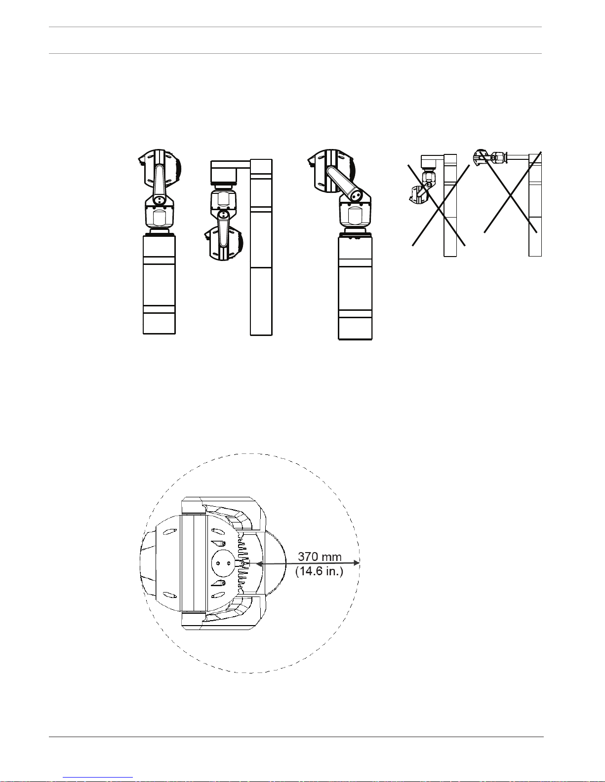
7.2 Select the Mounting Orientation
MIC Series cameras are designed to be mounted upright (straight up, 90°), inverted (straight
down, 90°), or canted upright (ball up, 45°). The tilt limits for the canted unit prevent it from
working properly if mounted ball down. See the figures below for illustrations of the correct
and the incorrect mounting orientations of MIC cameras.
Correct mounting orientation -
upright, inverted
Correct mounting orientation -
canted
Incorrect mounting orientation
Note the position of the visor when the camera is installed in inverted orientation. The visor is
close to the top of the pan shaft (the body of the MIC), instead of at the bottom of the
inverted camera.
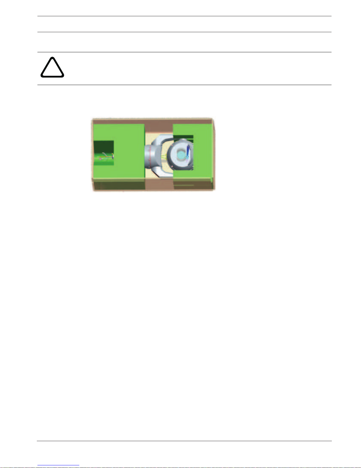
Note: For canted cameras, ensure that your mounting location provides the necessary
clearance (370 mm (14.6 in.)) for the camera head to pan.
Figure7.1: Top view of canted MIC7000 illustrating distance of pan clearance
The figure below illustrates the tilt range of the camera in upright orientation.

MIC IP starlight 7000 HD Mounting Location and Mounting Orientation | en 21
Bosch Security Systems Operation Manual 2016.07 | 5.0 | F.01U.291.520
55° 55°
90° 90°
AutoPivot
Figure7.2: MIC7000 Tilt Range: 145° each direction; 290° if AutoPivot enabled
22 en | Overview of Mounting Options MIC IP starlight 7000 HD
2016.07 | 5.0 | F.01U.291.520 Operation Manual Bosch Security Systems
8 Overview of Mounting Options
Bosch sells a complete series of mounting brackets that support multiple mounting
configurations.
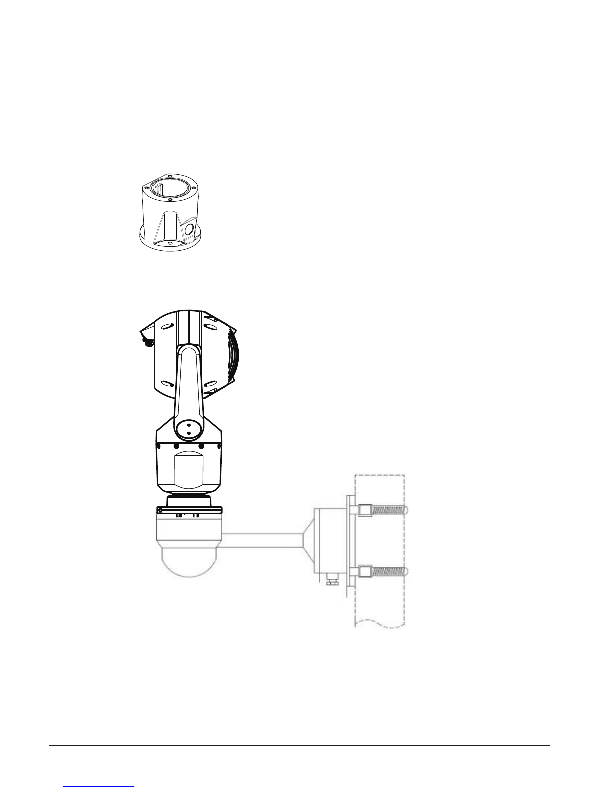
The most common type of mounting location is the top of a pole suitable to support CCTV
equipment and that provides a robust mounting platform to minimize camera motion and
typically has a large base cabinet for mounting ancillary equipment such as power supplies.
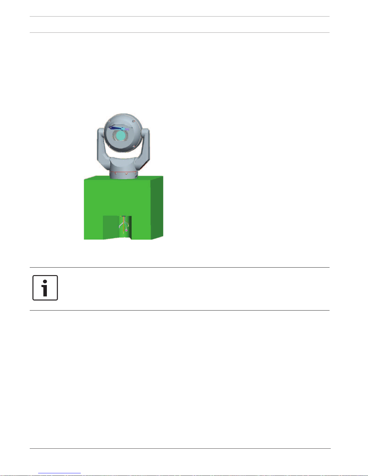
The hinged DCA is well-suited to installations on top of a pole.
Figure8.3: Typical hinged DCA mount configuration
The camera can also be mounted on the side of a lamp post, pole, or similar column using the
Pole Mount Bracket (MIC-PMB). Be aware that lamp posts can often be subject to movement
and are not suitable platforms in all conditions or for all applications.
The figure below identifies the three mounting brackets (each sold separately) that are
necessary to mount the MIC camera on the side of a pole.
Note: The figure identifies the part numbers, as well as the codes for the available colors (-BD
for black, WD for white, and GD for grey) of each mounting bracket.

MIC IP starlight 7000 HD Overview of Mounting Options | en 23
Bosch Security Systems Operation Manual 2016.07 | 5.0 | F.01U.291.520
MIC-WMB-BD,
-WD, -MG
MIC-SCA-BD,
-WD, -GD
MIC-PMB
Figure8.4: Typical Pole mount configuration
Other locations for mounting the camera include the top of a building, the side (wall) of a
building, the corner of a building, and under the eave of a building.
MIC-SPR-BD,
-WD, -GD
MIC-SCA-BD,
-WD, -GD
MIC-WMB-BD,
-WD, -MG
Figure8.5: Typical Wall mount configuration
MIC-CMB-BD,
-WD, -MG
MIC-SCA-BD,
-WD, -GD
MIC-WMB-BD,
-WD, -MG
Figure8.6: Typical Corner mount configuration
24 en | Overview of Mounting Options MIC IP starlight 7000 HD
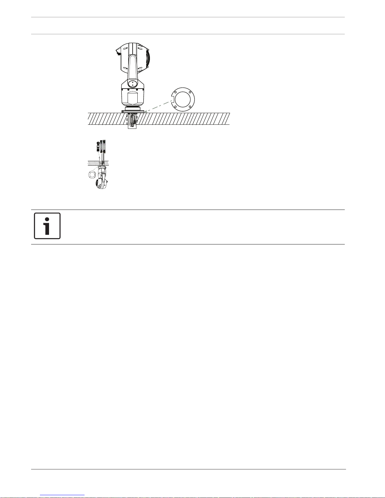
2016.07 | 5.0 | F.01U.291.520 Operation Manual Bosch Security Systems
Figure8.7: Direct surface mount – camera upright (MIC + base gasket)
Figure8.8: Direct surface mount – camera inverted (MIC + base gasket + IP67 Weatherization/Connector
Kit)
Notice!
Observe all appropriate safety precautions and local building regulations.
Refer to the MIC Series Mounting Brackets Installation Guide for installation instructions.
MIC IP starlight 7000 HD Install the Camera | en 25
Bosch Security Systems Operation Manual 2016.07 | 5.0 | F.01U.291.520
9 Install the Camera
!
Caution!
Installation must be made by qualified personnel and conform to ANSI/NFPA 70 (the National
Electrical Code® (NEC)), Canadian Electrical Code, Part I (also called CE Code or CSA C22.1),
and all applicable local codes. Bosch Security Systems, Inc. accepts no liability for any
damages or losses caused by incorrect or improper installation.
!
Caution!
ELECTRIC SHOCK HAZARD
To reduce the risk of electric shock, disconnect power to the camera and/or to the power
supply unit before moving the camera, before installing any accessories, and before mounting
the camera.
You can install the camera:
– onto a MIC-DCA or a MIC wall mount
or
– directly to a mounting surface using the MIC7000 IP67 Connector Kit (MICIP67-5pk, sold
separately).
Refer to the manual provided with the kit for installation instructions.
Notice!
To maintain the NEMA 6P rating when the camera is mounted to a MIC-DCA, installers must
ensure that the user-supplied cable glands or conduit connections have NEMA 6P ratings.
26 en | Make Connections - Power and Control MIC IP starlight 7000 HD
2016.07 | 5.0 | F.01U.291.520 Operation Manual Bosch Security Systems
10 Make Connections - Power and Control
10.1 About Camera Power and Control
The camera transmits PTZ control commands and images over a TCP/IP network. It also allows
users to configure the camera display settings, camera operating settings, and to configure
the network parameters.
The camera incorporates a network video server in the IP module. The primary function of the
server is to encode video and control data for transmission over a TCP/IP network. With its
H.264 encoding, it is ideally suited for IP communication and for remote access to digital video
recorders and multiplexers. The use of existing networks means that integration with CCTV
systems or local networks can be achieved quickly and easily. Video images from a single
camera can be simultaneously received on several receivers.
10.2 Power Source Options
The camera can be powered by a network compliant to High Power-over-Ethernet (Bosch’s
version of High PoE) using a Bosch model of High PoE Midspans (sold separately). With this
configuration, only a single (Cat5e/Cat6e) cable connection is required to view, to power, and
to control the camera.
The camera can also accept a standard 24 VAC power source if a High PoE network interface
will not be used. User-supplied wiring must be in compliance with electrical codes (Class 2
power levels).
For maximum reliability, the camera can be connected simultaneously to a High PoE Midspan
and a separate 24 VAC power source. If High PoE and 24 VAC are applied simultaneously, the
camera usually selects auxiliary input (24 VAC) and will draw minimal power from the High
PoE Midspan. If the 24 VAC power source fails, the camera switches power input seamlessly
to High PoE. After the 24 VAC power source is restored, the camera switches power input
again to 24 VAC.
!
Warning!
Bosch’s version of High PoE:
If supplying power to the camera by HPoE or a midspan device, you must install additional
surge protection.
In the table below, an "X" identifies the power source options for MIC7000 camera models.
CAMERA MODELS 60 W midspan 95 W midspan VIDEOJET connect 24 VAC PSU
Models with illuminator X X X
Models without
illuminator
X X X X
The table below identifies the power devices that can be connected simultaneously to the
camera.
If power is supplied from: Camera can receive power simultaneously from:
60 W midspan (NPD-6001A)
24 VAC PSU
(VG4-A-PSU1, VG4-A-PSU2)
95 W midspan (NPD-9501A)
VIDEOJET connect (VJC-7000-90)
MIC IP starlight 7000 HD Make Connections - Power and Control | en 27
Bosch Security Systems Operation Manual 2016.07 | 5.0 | F.01U.291.520
!
Caution!
Compliance with EN50130-4 Alarm Standard – CCTV for Security Applications
To meet the requirements of the EN50130-4 Alarm Standard, an ancillary uninterruptable
power (UPS) supply is necessary. The UPS must have a Transfer Time between 2–6 ms and a
Backup Runtime of greater than 5 seconds for the power level as specified on the product
datasheet.
10.3 Ethernet Connections
!
Caution!
Ethernet cables must be routed through earth-grounded conduit capable of withstanding the
outdoor environment.
Note: Consult the National Electrical Code (NEC) for cable bundling requirements and
limitations.
Cable Type Cat5e/Cat6e Ethernet (directly to the camera, or to a network switch
between the camera and the network)
Maximum Distance 100 m (330 ft)
Bandwidth 10BASE-T/100BASE-TX, auto-sensing, half/full duplex
High PoE (95W required for models
with illuminators)
Use the 95 W midspan sold by Bosch.
High PoE (60W only for models
without illuminators)
Use the 60 W midspan sold by Bosch, or a midspan that is compliant to the
IEEE 802.3at, class 4 standard.
Terminal Connector RJ45, Male
28 en | Make Connections - Power and Control MIC IP starlight 7000 HD
2016.07 | 5.0 | F.01U.291.520 Operation Manual Bosch Security Systems
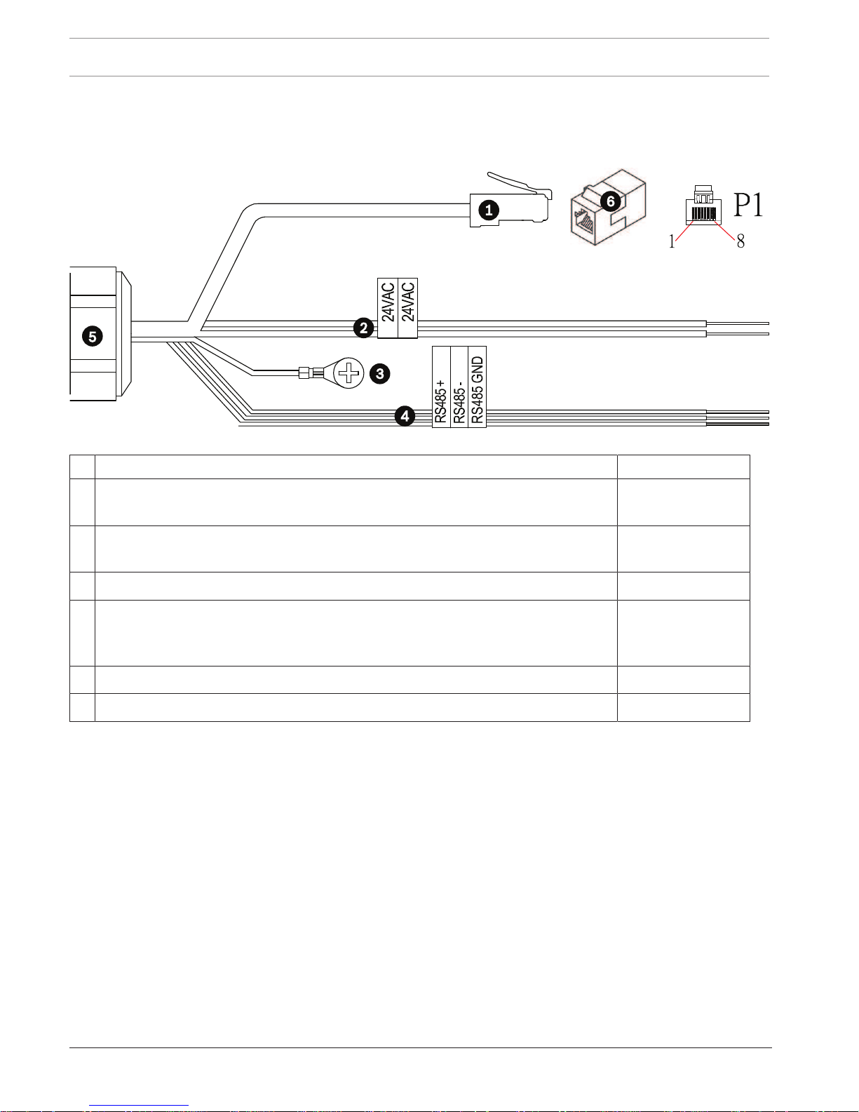
10.4 Camera Connections
All electrical and data connections from the camera are made from the connectors in the base
of the camera.
Figure10.9: MIC7000 connectors
Description Wire Color
1 RJ45 (Cat5e/Cat6e) connector (male) (supporting High PoE) for power and
communication between a Bosch model of High PoE Midspan or a VJC-7000-90
2 24 VAC power wires (24 gage) to VG4-A-PSU1 or VG4-A-PSU2 (if not using a PoE
network)
Line (L) = Black
Neutral (N) = White
3 Chassis (Earth) ground wire (18 gage) with connector lug Green
4 RS-485 connections for communication to / from the MIC-ALM-WAS-24 + = Purple
- = Yellow
GND = Brown
5 Liquid-tight cordgrip in the base of the camera
6 RJ45 coupler (female to female)
Note: If the MIC camera will be installed directly to a mounting surface, instead of onto a MIC
DCA or a MIC wall mount bracket, Bosch recommends using the MIC7000 IP67 Connector Kit
(MICIP67-5pk, sold separately) to protect the connections against moisture and dust particles.
Each kit provides components for connecting as many as 5 MIC7000 cameras.
MIC IP starlight 7000 HD Make Connections - Power and Control | en 29
Bosch Security Systems Operation Manual 2016.07 | 5.0 | F.01U.291.520
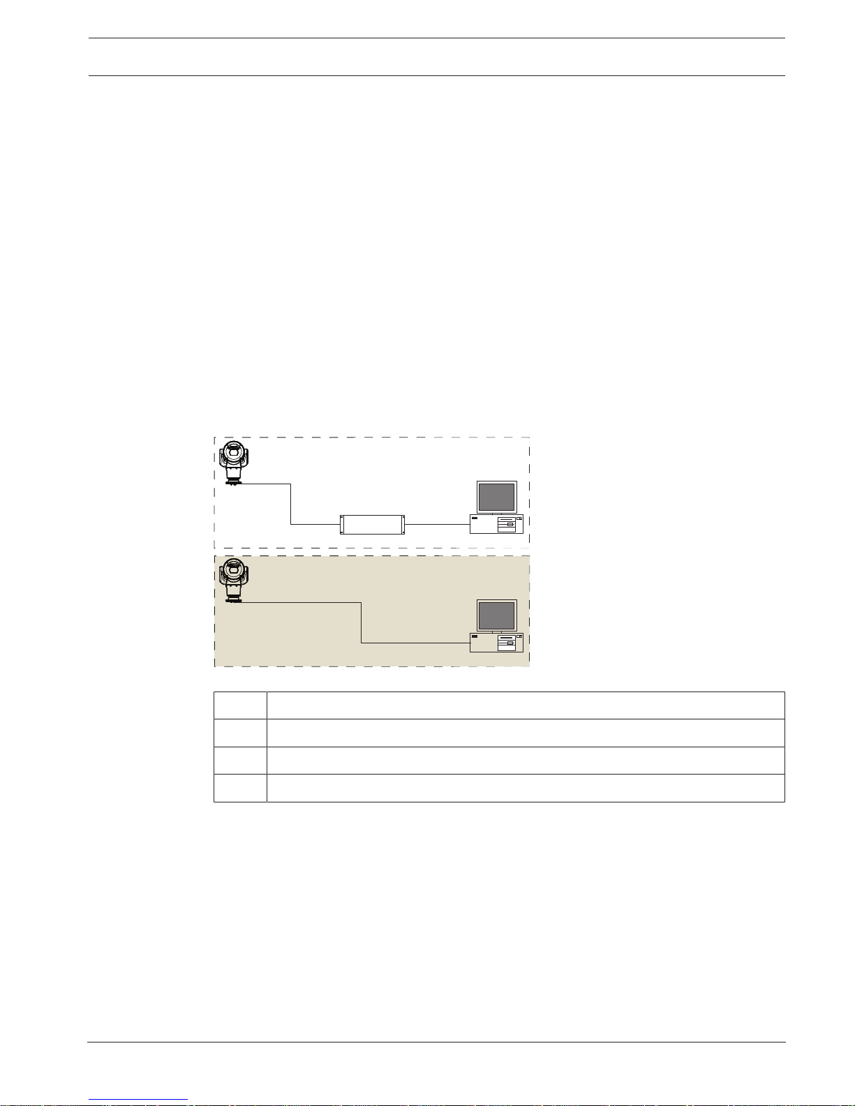
10.5 Connect the Camera to the Network
Note: Refer to the following figure for an illustration of both options.
Option A:
1. Connect an Ethernet cable (Cat5e/Cat6) from the RJ45 connector of the camera to a
network switch attached to the Local Area Network (LAN).
2. Connect the dedicated network switch to the RJ45 connector on the computer.
3. Connect the 24 VAC wires to the power source.
4. Connect the RS-485 wires to the MIC-ALM-WAS-24 (optional).
5. Attach the green ground wire (item 3 in the figure above) from the camera to an earthground connection on the mounting surface using the supplied screw or a suitable usersupplied fastener.
Option B:
1. Connect an Ethernet crossover cable from the RJ45 connector of the camera directly to a
networking device such as a computer, a DVR/NVR, etc.
2. Attach the green ground wire (item 3 in the figure above) from the camera to an earthground connection on the mounting surface using the supplied screw or a suitable usersupplied fastener.
1
2
3
4
1
2
2
A
4
B
Figure10.10: MIC7000 IP System Configuration
1 MIC7000 camera
2 IP connection
3 Network switch
4 Networking device (computer, DVR/NVR, etc.)
30 en | Cant the Camera MIC IP starlight 7000 HD
2016.07 | 5.0 | F.01U.291.520 Operation Manual Bosch Security Systems
11 Cant the Camera
Note:
For simplicity, the graphics in this section are only of the camera (and the specific accessory
that you are installing, if applicable). The graphics do not depict other accessories that you
may have installed already.
MIC7000 cameras feature on-site canting functionality.
Installers can adjust the camera from an upright position to a canted position if desired. This
allows the camera to be installed at a 45º angle so that its field of view (FOV) can observe the
scene directly beneath the camera.
Note: Canting is not applicable when the camera is installed in inverted orientation.
!
Warning!
Risk of bodily injury.
Unplug the device from its power source before canting the device. Ensure that the head is
supported so that it doesn't tilt downward unexpectedly after the Torx screws are removed
from the yoke arms and pinch fingers or other body parts.
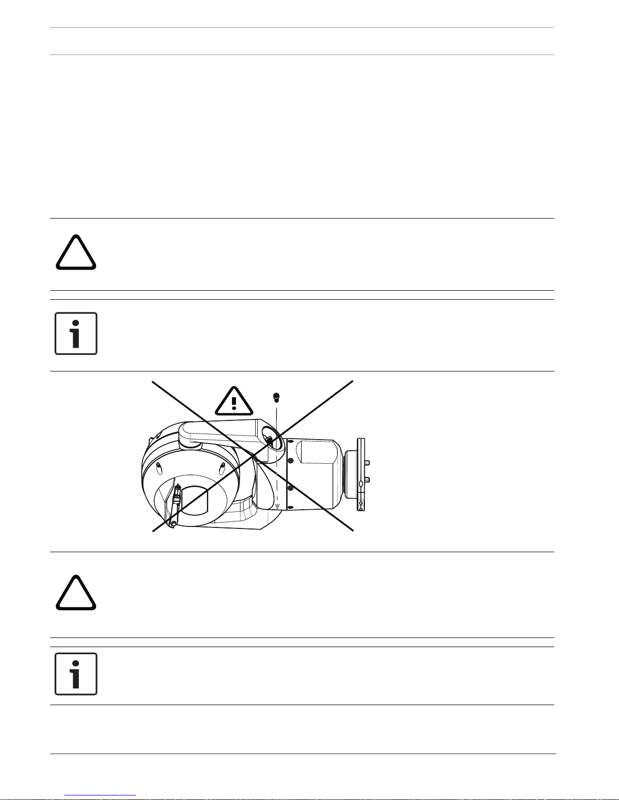
Notice!
Risk of damage to the camera
Do not, under any circumstances, cant the camera while the camera is on its side. Cant the
camera from an upright position only, in order to prevent screws or other objects from falling
into the open spaces in the arms when the yoke caps are removed.
Figure11.11: Do NOT allow screws or other objects to fall inside camera!
!
Warning!
Risk of bodily injury.
Do not stand the canted (45°) MIC camera upright on the camera base or on an unsecured
DCA, with the DCA base upright! It is unstable and might fall and cause bodily injury and/or
damage to the camera. Bosch strongly recommends canting the camera after attaching it to a
DCA and mounting it in the desired location.
Notice!
If your MIC camera will be canted, install the sunshield first.
If your MIC camera will have both illuminator and sunshield accessories, install the illuminator
first.
To cant the camera, follow these steps:
 Loading...