


MIC-500-ALB18N
Bosch MIC-500-ALB18N, MIC-500-ALB18P, MIC-500-ALB36N, MIC-500-ALB36P, MIC-500-ALW18N User Manual
...
MIC Series 500 Camera
MIC Series 500
en User’s Manual


MIC Series 500 Camera Table of Contents | en 3
Bosch Security Systems, Inc. User’s Manual F.01U.173.601 | 2.0 | 2010.11
Table of Contents
1Safety 5
1.1 Important Safety Instructions 5
1.2 Safety Precautions 6
1.3 Important Notices 7
1.4 Customer Support and Service 11
2 Unpacking 12
2.1 Parts List 12
2.2 Additional Tools Required 12
3 Description 13
3.1 Features 13
3.2 Power 13
3.3 Video 13
4Mounting 14
4.1 Adjusting the MIC 500 Series Camera 15
4.2 Adjusting the Rain Shield for Inverted Operation 17
4.3 Mounting the MIC 500 Series Camera 18
4.4 Earthing the MIC 500 Series Camera 19
4.5 Lightning Protection 19
4.6 Electrical Connections 19
5 Navigating the Menus 22
5.1 MIC Setups Menu 24
5.1.1 Config Mode 26
5.2 Activate Feature Menu 26
5.3 Preset Tour Menu 26
5.3.1 Create/Modify Tour 27
5.3.2 Random Tours 27
5.4 Pattern Tour Menu 28
5.5 Presets Menu 29
5.5.1 Learn Preset 29
5.5.2 GOTO Preset 29
5.5.3 Manual Control 30
5.6 Communications Menu 30
5.7 Advanced Setups Menu 31
5.7.1 Factory Defaults 33
5.7.2 Re-map Pelco Aux (Pelco D and P Protocols only) 33
5.8 Alarms Menu 34
5.8.1 Alarm Relays and Re-arm Time 35
5.9 Sony Set Menu 35
5.9.1 Mapping to a MIC 500 Series Camera Function 36
5.10 Captions Menu 42
5.10.1 Default Caption 43

4 en | Table of Contents MIC Series 500 Camera
F.01U.173.601 | 2.0 | 2010.11 User’s Manual Bosch Security Systems, Inc.
5.10.2 Preset Captions 43
5.10.3 Sector Captions 43
5.10.4 Setting Captions 43
5.11 Privacy Menu 45
5.11.1 Mask / Clear Whole 45
5.11.2 Setting the Privacy Zones 45
5.12 Pot Test Menu 46
5.13 MIC Information Menu 46
5.13.1 MIC Information Menus 48
5.14 Set User Access Menu 48
5.14.1 Factory Defaults 49
5.15 Help Menu 50
5.16 Self Diagnosis 50
A Appendices 51
A.1 MIC 500 Series Aux Controls 51
A.2 MIC 500 Preset Controls 52
A.3 MIC 500 Model Numbers and Descriptions 54

MIC Series 500 Camera Safety | en 5
Bosch Security Systems, Inc. User’s Manual F.01U.173.601 | 2.0 | 2010.11
1Safety
1.1 Important Safety Instructions
Read, follow, and retain for future reference all of the following safety instructions. Heed all
warnings on the unit and in the operating instructions before operating the unit.
1. Cleaning - Unplug the unit from the outlet before cleaning. Follow any instructions
provided with the unit. Generally, using a dry cloth for cleaning is sufficient, but a moist
fluff-free cloth or leather shammy may also be used. Do not use liquid cleaners or aerosol
cleaners.
2. Heat Sources - Do not install the unit near any heat sources such as radiators, heaters,
stoves, or other equipment (including amplifiers) that produce heat.
3. Ventilation - The MIC 500 Series camera is a completely sealed unit and requires no
special consideration as regards to ventilation.
4. Water - Do not install the camera power supply near water for example near a bathtub,
washbowl or swimming pool. The power supplies carry an IP65 rating and are suitable for
outside installation but for security reasons Bosch recommend that they are installed in a
suitable equipment cabinet. The camera unit is sealed to IP68 and can be safely used in
damp environments or outdoors, as long as the base cable connector is suitably sealed.
5. Object and liquid entry - With the exception of the base connector, the MIC 500 Series
Camera can be exposed to non corrosive liquids without damage. Never push objects
into the base connector as this may damage the connection pins and prevent the camera
operating correctly.
6. Lightning - For added protection during a lightning storm, or when leaving this unit
unattended and unused for long periods, unplug the unit from the wall outlet and
disconnect the cable system. This will prevent damage to the unit from lightning and
power line surges.
7. Controls adjustment - Adjust only those controls specified in the operating instructions.
Improper adjustment of other controls may cause damage to the unit.
8. Overloading - Do not overload outlets and extension cords. This can cause fire or
electrical shock.
9. Power cord and plug protection - Protect the plug and power cord from foot traffic,
being pinched by items placed upon or against them at electrical outlets, and its exit
from the unit. For units intended to operate with 230 VAC, 50 Hz, the input and output
power cord must comply with the latest versions of IEC Publication 227 or IEC
Publication 245.
10. Power disconnect - Units with or without ON/OFF switches have power supplied to the
unit whenever the power cord is inserted into the power source; however, the unit is
operational only when the ON/OFF switch is in the ON position. The power cord is the
main power disconnect device for switching off the voltage for all units.
11. Power sources - Operate the unit only from the type of power source indicated on the
label. Before proceeding, be sure to disconnect the power from the cable to be installed
into the unit.
– For battery powered units, refer to the operating instructions.
– For external power supplied units, use only the recommended or approved power
supplies.
– For limited power source units, this power source must comply with EN60950.
Substitutions may damage the unit or cause fire or shock.
– For 24 VAC units, voltage applied to the unit's power input should not exceed ±10%,
or 28 VAC. User-supplied wiring must comply with local electrical codes (Class 2
6 en | Safety MIC Series 500 Camera
F.01U.173.601 | 2.0 | 2010.11 User’s Manual Bosch Security Systems, Inc.
power levels). Do not ground the supply at the terminals or at the unit's power
supply terminals.
– If unsure of the type of power supply to use, contact your dealer or local power
company.
12. Servicing - Do not attempt to service this unit yourself. Opening or removing covers may
expose you to dangerous voltage or other hazards. Refer all servicing to qualified service
personnel.
13. Damage requiring service - Unplug the unit from the main AC power source and refer
servicing to qualified service personnel when any damage to the equipment has
occurred, such as:
– the power supply cord or plug is damaged;
– liquid has been spilled in the equipment;
– an object has fallen into the unit;
– the unit has been dropped or the unit cabinet is damaged;
– the unit exhibits a distinct change in performance;
– the unit does not operate normally when the user correctly follows the operating
instructions.
14. Replacement parts - Be sure the service technician uses replacement parts specified by
the manufacturer, or that have the same characteristics as the original parts.
Unauthorized substitutions may cause fire, electrical shock, or other hazards.
15. Safety check - Safety checks should be performed upon completion of service or repairs
to the unit to ensure proper operating condition.
16. Installation - Install in accordance with the manufacturer's instructions and in
accordance with applicable local codes.
17. Attachments, changes or modifications - Only use attachments/accessories specified by
the manufacturer. Any change or modification of the equipment, not expressly approved
by Bosch, could void the warranty or, in the case of an authorization agreement, authority
to operate the equipment.
1.2 Safety Precautions
DANGER!
This symbol indicates an imminently hazardous situation such as “Dangerous Voltage” inside
the product. If not avoided, this will result in an electrical shock, serious bodily injury, or
death.
WARNING!
Indicates a potentially hazardous situation. If not avoided, this could result in serious bodily
injury or death.
CAUTION!
Indicates a potentially hazardous situation. If not avoided, this may result in minor or
moderate injury. Alerts the user to important instructions accompanying the unit.
CAUTION!
Indicates a potentially hazardous situation. If not avoided, this may result in property damage
or risk of damage to the unit.
MIC Series 500 Camera Safety | en 7
Bosch Security Systems, Inc. User’s Manual F.01U.173.601 | 2.0 | 2010.11
1.3 Important Notices
Accessories - Do not place this unit on an unstable stand, tripod, bracket, or mount. The unit
may fall, causing serious injury and/or serious damage to the unit. Use only with the cart,
stand, tripod, bracket, or table specified by the manufacturer. When a cart is used, use
caution and care when moving the cart/apparatus combination to avoid injury from tip-over.
Quick stops, excessive force, or uneven surfaces may cause the cart/unit combination to
overturn. Mount the unit per the manufacturer's instructions.
All-pole power switch - Incorporate an all-pole power switch, with a contact separation of at
least 3 mm in each pole, into the electrical installation of the building.If it is needed to open
the housing for servicing and/or other activities, use this all-pole switch as the main
disconnect device for switching off the voltage to the unit.
Camera grounding - For mounting the camera in potentially damp environments, ensure to
ground the system using the ground connection of the power supply connector (see section:
Connecting external power supply).
Camera lens - An assembled camera lens in the outdoor housing must comply and be tested
in accordance with UL/IEC60950. Any output or signal lines from the camera must be SELV or
Limited Power Source. For safety reasons the environmental specification of the camera lens
assembly must be within the environmental specification of -10 °C (14 °F) to 50 °C (122 °F).
Camera signal - Protect the cable with a primary protector if the camera signal is beyond 140
feet, in accordance with NEC800 (CEC Section 60).
Coax grounding:
– Ground the cable system if connecting an outside cable system to the unit.
– Connect outdoor equipment to the unit's inputs only after this unit has had its grounding
plug connected to a grounded outlet or its ground terminal is properly connected to a
ground source.
– Disconnect the unit's input connectors from outdoor equipment before disconnecting
the grounding plug or grounding terminal.
– Follow proper safety precautions such as grounding for any outdoor device connected to
this unit.
U.S.A. models only - Section 810 of the National Electrical Code, ANSI/NFPA No.70, provides
information regarding proper grounding of the mount and supporting structure, grounding of
the coax to a discharge unit, size of grounding conductors, location of discharge unit,
connection to grounding electrodes, and requirements for the grounding electrode.
Your Bosch product was developed and manufactured with high-quality material and
components that can be recycled and reused. This symbol means that electronic and
electrical appliances, which have reached the end of their working life, must be collected and
disposed of separately from household waste material. Separate collecting systems are
usually in place for disused electronic and electrical products. Please dispose of these units at
an environmentally compatible recycling facility, per European Directive 2002/96/EC.
NOTICE!
This symbol indicates information or a company policy that relates directly or indirectly to the
safety of personnel or protection of property.
NOTICE!
This device is intended for use in public areas only.
U.S. federal law strictly prohibits surreptitious recording of oral communications.

8 en | Safety MIC Series 500 Camera
F.01U.173.601 | 2.0 | 2010.11 User’s Manual Bosch Security Systems, Inc.
Environmental statement - Bosch has a strong commitment towards the environment. This
unit has been designed to respect the environment as much as possible.
Electrostatic-sensitive device - Use proper CMOS/MOS-FET handling precautions to avoid
electrostatic discharge.
NOTE: Wear required grounded wrist straps and observe proper ESD safety precautions when
handling the electrostatic-sensitive printed circuit boards.
Fuse rating - For security protection of the device, the branch circuit protection must be
secured with a maximum fuse rating of 16A. This must be in accordance with NEC800 (CEC
Section 60).
Grounding and polarization - This unit may be equipped with a polarized alternating current
line plug (a plug with one blade wider than the other blade). This safety feature allows the
plug to fit into the power outlet in only one way. If unable to insert the plug fully into the
outlet, contact a locally certified electrician to replace the obsolete outlet. Do not defeat the
safety purpose of the polarized plug.
Alternately, this unit may be equipped with a 3-pole grounding plug (a plug with a third pin for
earth grounding). This safety feature allows the plug to fit into a grounded power outlet only.
If unable to insert the plug into the outlet, contact a locally certified electrician to replace the
obsolete outlet. Do not defeat the safety purpose of the grounding plug.
Moving - Disconnect the power before moving the unit. Move the unit with care. Excessive
force or shock may damage the unit.
Outdoor signals - The installation for outdoor signals, especially regarding clearance from
power and lightning conductors and transient protection, must be in accordance with NEC725
and NEC800 (CEC Rule 16-224 and CEC Section 60).
Permanently connected equipment - Incorporate a readily accessible disconnect device in
the building installation wiring.
Pluggable equipment - Install the socket outlet near the equipment so it is easily accessible.
Power disconnect - Units have power supplied whenever the power cord is inserted into the
power source. The power cord is the main power disconnect for all units.
Power lines - Do not locate the camera near overhead power lines, power circuits, or
electrical lights, nor where it may contact such power lines, circuits, or lights.
Video loss - Video loss is inherent to digital video recording; therefore, Bosch Security
Systems cannot be held liable for any damage that results from missing video information. To
minimize the risk of lost digital information, Bosch Security Systems recommends multiple,
redundant recording systems, and a procedure to back up all analog and digital information.
FCC & ICES Information
(U.S.A. and Canadian Models Only)
This equipment has been tested and found to comply with the limits for a Class B digital
device, pursuant to part 15 of the FCC Rules. These limits are designed to provide reasonable
protection against harmful interference in a residential installation. This equipment
generates, uses, and can radiate radio frequency energy and, if not installed and used in
accordance with the instructions, may cause harmful interference to radio communications.
However, there is no guarantee that interference will not occur in a particular installation. If
this equipment does cause harmful interference to radio or television reception, which can be
NOTICE!
This is a class B product. In a domestic environment this product may cause radio
interference, in which case the user may be required to take adequate measures.

MIC Series 500 Camera Safety | en 9
Bosch Security Systems, Inc. User’s Manual F.01U.173.601 | 2.0 | 2010.11
determined by turning the equipment off and on, the user is encouraged to try to correct the
interference by one or more of the following measures:
– reorient or relocate the receiving antenna;
– increase the separation between the equipment and receiver;
– connect the equipment into an outlet on a circuit different from that to which the
receiver is connected;
– consult the dealer or an experienced radio/TV technician for help.
Intentional or unintentional modifications, not expressly approved by the party responsible
for compliance, shall not be made. Any such modifications could void the user's authority to
operate the equipment. If necessary, the user should consult the dealer or an experienced
radio/television technician for corrective action.
The user may find the following booklet, prepared by the Federal Communications
Commission, helpful: How to Identify and Resolve Radio-TV Interference Problems. This booklet
is available from the U.S. Government Printing Office, Washington, DC 20402, Stock No. 004000-00345-4.
INFORMATIONS FCC ET ICES
(modèles utilisés aux États-Unis et au Canada uniquement)
Suite à différents tests, cet appareil s'est révélé conforme aux exigences imposées aux
appareils numériques de classe B, en vertu de la section 15 du règlement de la Commission
fédérale des communications des États-Unis (FCC), et en vertu de la norme ICES-003 d'Industrie
Canada. Ces exigences visent à fournir une protection raisonnable contre les interférences
nuisibles lorsque l'appareil est utilisé dans le cadre d'une installation résidentielle. Cet
appareil génère, utilise et émet de l'énergie de radiofréquences et peut, en cas d'installation
ou d'utilisation non conforme aux instructions, engendrer des interférences nuisibles au
niveau des radiocommunications. Toutefois, rien ne garantit l'absence d'interférences dans
une installation particulière. Il est possible de déterminer la production d'interférences en
mettant l'appareil successivement hors et sous tension, tout en contrôlant la réception radio
ou télévision. L'utilisateur peut parvenir à éliminer les interférences éventuelles en prenant
une ou plusieurs des mesures suivantes:
– Modifier l'orientation ou l'emplacement de l'antenne réceptrice;
– Éloigner l'appareil du récepteur;
– Brancher l'appareil sur une prise située sur un circuit différent de celui du récepteur;
– Consulter le revendeur ou un technicien qualifié en radio/télévision pour obtenir de
l'aide.
Toute modification apportée au produit, non expressément approuvée par la partie
responsable de l'appareil, est strictement interdite. Une telle modification est susceptible
d'entraîner la révocation du droit d'utilisation de l'appareil.
La brochure suivante, publiée par la Commission fédérale des communications (FCC), peut
s'avérer utile : How to Identify and Resolve Radio-TV Interference Problems (Comment identifier
et résoudre les problèmes d’interférences de radio et de télévision). Cette brochure est
disponible auprès du U.S. Government Printing Office, Washington, DC 20402, États-Unis,
sous la référence n° 004-000-00345-4.
Disclaimer
Underwriter Laboratories Inc. (“UL”) has not tested the performance or reliability of the
security or signaling aspects of this product. UL has only tested fire, shock and/or casualty
hazards as outlined in UL's Standard(s) for Safety for Closed Circuit Television Equipment, UL
2044. UL Certification does not cover the performance or reliability of the security or signaling
aspects of this product.

10 en | Safety MIC Series 500 Camera
F.01U.173.601 | 2.0 | 2010.11 User’s Manual Bosch Security Systems, Inc.
UL MAKES NO REPRESENTATIONS, WARRANTIES, OR CERTIFICATIONS WHATSOEVER
REGARDING THE PERFORMANCE OR RELIABILITY OF ANY SECURITY OR SIGNALING RELATED
FUNCTIONS OF THIS PRODUCT.
Disclaimer
Underwriter Laboratories Inc. (“UL”) has not tested the performance or reliability of the
security or signaling aspects of this product. UL has only tested fire, shock and/or casualty
hazards as outlined in UL's Standard(s) for Safety for Information Technology Equipment, UL
60950-1. UL Certification does not cover the performance or reliability of the security or
signaling aspects of this product.
UL MAKES NO REPRESENTATIONS, WARRANTIES, OR CERTIFICATIONS WHATSOEVER
REGARDING THE PERFORMANCE OR RELIABILITY OF ANY SECURITY OR SIGNALINGRELATED FUNCTIONS OF THIS PRODUCT.
Copyright
This user guide is the intellectual property of Bosch Security Systems, Inc. and is protected by
copyright.
All rights reserved.
Trademarks
All hardware and software product names used in this document are likely to be registered
trademarks and must be treated accordingly.
NOTICE!
This user guide has been compiled with great care and the information it contains has been
thoroughly verified. The text was complete and correct at the time of printing. The ongoing
development of the products may mean that the content of the user guide can change without
notice. Bosch Security Systems accepts no liability for damage resulting directly or indirectly
from faults, incompleteness or discrepancies between the user guide and the product
described.

MIC Series 500 Camera Safety | en 11
Bosch Security Systems, Inc. User’s Manual F.01U.173.601 | 2.0 | 2010.11
1.4 Customer Support and Service
If this unit needs service, contact the nearest Bosch Security Systems Service Center for
authorization to return and shipping instructions.
Service Centers
USA
Repair Center
Telephone: 800-566-2283
Fax: 800-366-1329
E-mail: repair@us.bosch.com
Customer Service
Telephone: 888-289-0096
Fax: 585-223-9180
E-mail: security.sales@us.bosch.com
Technical Support
Telephone: 800-326-1450
Fax: 585-223-3508 or 717-735-6560
E-mail: technical.support@us.bosch.com
Canada
Telephone: 514-738-2434
Fax: 514-738-8480
Europe, Middle East, Africa Region
Repair Center
Telephone: 31 (0) 76-5721500
Fax: 31 (0) 76-5721413
E-mail: RMADesk.STService@nl.bosch.com
Asia Region
Repair Center
Telephone: 65 63522776
Fax: 65 63521776
E-mail: rmahelpdesk@sg.bosch.com
Customer Service
Telephone: 86 (0) 756 7633117 or
86 (0) 756 7633121
Fax: 86 (0) 756 7631710
E-mail: customer.service@cn.bosch.com
Warranty and additional information
For additional information and warranty queries, please contact your Bosch Security Systems
representative or visit our website at www.boschsecurity.com.

12 en | Unpacking MIC Series 500 Camera
F.01U.173.601 | 2.0 | 2010.11 User’s Manual Bosch Security Systems, Inc.
2 Unpacking
This equipment should be unpacked and handled with care. If an item appears to have been
damaged in shipment, notify the shipper immediately.
Verify that all the parts listed in the Parts List below are included. If any items are missing,
notify your Bosch Security Systems Sales or Customer Service Representative.
The original packing carton is the safest container in which to transport the unit and must be
used if returning the unit for service. Save it for possible future use.
2.1 Parts List
The package containing the MIC 500 Series Camera should include the following items:
2.2 Additional Tools Required
The following table lists additional tools required (not supplied by Bosch):
NOTICE!
Do not stand the canted (45°) MIC 500 Series Camera upright as it is unstable unless properly
mounted.
Quantity Part
1 MIC 500 Series Camera
1 Installation and Configuration CD (including user manuals and protocol packs)
1 Quick Installation Guide
1 MIC-USB485CVTR signal converter (enabling connection of MIC 500 Series
Camera to a PC)
Quantity Part
1 13 mm spanner for MIC 500 Series Camera PCD foot, fixing bolts
1 3 mm screwdriver for the terminal blocks in power supply
1 8 mm screwdriver for MIC Series PSU enclosure fixing screws
1 No. 2 Phillips screwdriver for MIC 500 Series Camera rain shield adjustment, if
required
1 Nebar gasket or suitable silicone sealant for ensuring a water tight seal

MIC Series 500 Camera Description | en 13
Bosch Security Systems, Inc. User’s Manual F.01U.173.601 | 2.0 | 2010.11
3 Description
The MIC 500 Series Camera is a fully functional, quality built, pan/tilt/zoom CCTV camera
which has been designed to provide a robust, high quality, feature rich CCTV solution suitable
for most security applications. The camera features an IP68 weatherproof, robust, cast
aluminium housing for lightweight strength and durability utilizing brushless motors for
precise control and quiet operation. Comprehensive onboard software allows an installer to
configure a new MIC 500 Series camera for use quickly, or for a CCTV operator to set up
presets, tours, alarms (if fitted), privacy masks (if fitted) easily, and to control nearly all other
camera functions directly from the CCTV control room, no matter which control system is in
use. In addition, the camera can also be configured from a PC using the MIC Series Universal
Camera Setup Software (cam-set) and the MIC-USB485CVTR converter, both provided with
the camera.Bosch Security Systems’ MIC Series Universal Camera Setup Software is also
referred to as 'cam-set' within the product literature hereafter. Please see the MICUSB485CVTR and the MIC Series Universal Camera Setup Software Installation Manual or the
Cam-set help file for details on connecting the MIC-USB485CVTR to the MIC 500 Series
camera.
3.1 Features
The MIC 500 Series Camera has been designed with the following features:
– Brushless motor technology for quiet whisper operation
– Multi-protocol operation
– On-screen menu for configuration and operation
– Privacy function (if fitted; see model numbers in Appendix)
– New “twist-lock” canting for easy field adjustment
– Industry-leading programmable camera module function
– Wide range of mounting options for varied applications in even the harshest
environments
– Optically flat viewing window
– Reversible rain shield
– IP68 rating
3.2 Power
The recommended power cable is a 2-conductor, 14-18 gauge cable, depending on the
distance (cables MIC-2MS, MIC-10MS, MIC-20MS, MIC-25MS).
3.3 Video
The video coax cable should use a shield coverage copper braid 95% and standard copper
center conductor. Recommended cables are RG-59, RG-6/U, or RG-11U.
Cable Type Maximum Distance
RG-59/U 300 m (1000 ft)
RG-6/U 450 m (1500 ft)
RG-11/U 600 m (2000 ft)
Size O.D. between 4.6 mm (0.181 in.) and 7.9 mm (0.312 in.)
Shield Copper braid: 95%
Central Conductor Standard copper center
Terminal Connector BNC

14 en | Mounting MIC Series 500 Camera
F.01U.173.601 | 2.0 | 2010.11 User’s Manual Bosch Security Systems, Inc.
4 Mounting
Installation should be made by qualified service personnel and conform to the National
Electrical Code and applicable local codes.
The MIC 500 Series Camera range has been designed for easy installation on a variety of
common fittings. The most common type of mount used is a dedicated CCTV camera pole
where the camera is bolted directly to the top of the pole using industry standard 4 in. (101.6
mm) fittings. This type of camera pole provides a robust mounting platform that minimizes
camera motion and typically has a large base cabinet for mounting ancillary equipment such
as power supplies.
The camera can also be mounted on lamp post columns using the Pole Mount Bracket (MICPMB); however, users should be aware that lamp posts can often be subject to movement and
are not suitable platforms in all conditions or for all applications.
The following mounting brackets are available:
For mounting directly to a building, brackets are available for all typical building installations
such as upright (90°), canted (45°), or inverted.
Figure 4.1 Typical pole mount arrangement (MIC-PMB with MIC-SCA and MIC-WMB)
Figure 4.2 Typical wall mounting arrangement (MIC-SPA, MIC-SCA and MIC-WMB)
Part Description
MIC-SPA Wall Spreader Plate
MIC-PMB Pole Mount Bracket
MIC-CMB Corner Mount Bracket
MIC-WMB Wall Mount Bracket
MIC-SCA Shallow Conduit Adaptor
MIC-DCA Deep Conduit Adaptor
MIC Series 500 Camera Mounting | en 15
Bosch Security Systems, Inc. User’s Manual F.01U.173.601 | 2.0 | 2010.11
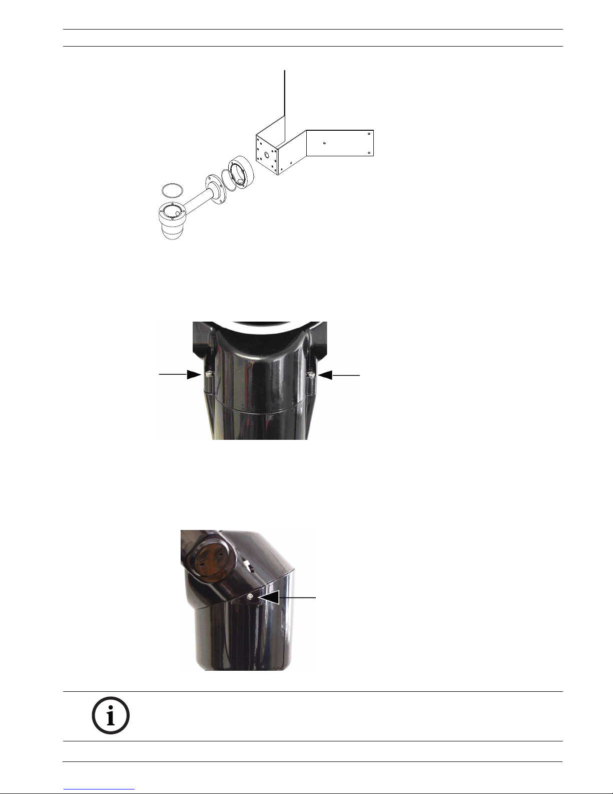
Figure 4.3 Typical wall corner mounting arrangement (MIC-CMB, MIC-SCA and MIC-WMB)
4.1 Adjusting the MIC 500 Series Camera
The MIC 500 Series Camera is suitable for adjustment from the upright position (90°) to a
canted (45°) position.
Figure 4.4 Pan body fixing screws
To adjust the MIC 500 Series Camera, follow these steps:
1. Firmly secure the camera base by the 4 inch PCD foot bolts.
2. Locate and remove the two (2) pan body fixing screws. Once the screws have been
loosened, lift them up and continue turning to lock the screws open. Ensure not to
damage the paint work on the camera.
Figure 4.5 Security screws
NOTICE!
The small security screws are not designed to be removed. Any attempt to remove these
screws will void the warranty and potentially cause serious damage to the camera.
16 en | Mounting MIC Series 500 Camera
F.01U.173.601 | 2.0 | 2010.11 User’s Manual Bosch Security Systems, Inc.
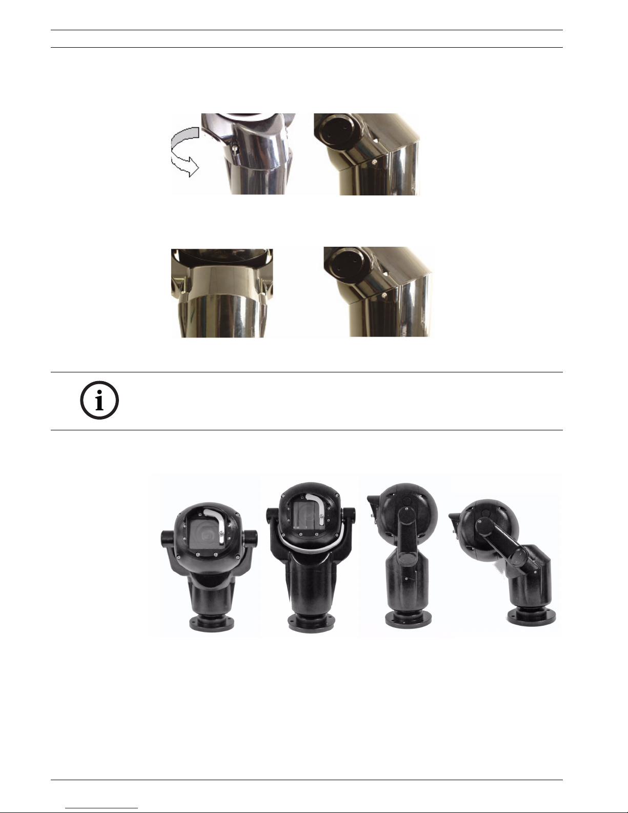
3. Grasp the lower camera body beneath the pan body joint and then carefully twist the
upper camera body clockwise until the camera body has rotated 180° around, canting the
top part of the camera to the 45° angle. Ensure that the securing bolt holes are aligned.
Figure 4.6 Canting in progress
4. Carefully replace and tighten the pan body securing the supplied (MIC-DCA, MIC-SCA,
MIC-WMB) bolts. Ensure not to damage the paint work on the camera.
Figure 4.7 Camera canted
5. The MIC 500 Series Camera is now ready to be installed and configured.
The following graphic shows the various positions of the MIC 500 Series Camera. See the
table below for the descriptions.
Figure 4.8 MIC 500 Series Cameras (From left to right: Canted full frontal view; Upright full frontal view;
Upright side view; Canted side view)
NOTICE!
Installation should be made by qualified service personnel and conform to the National
Electrical Code and applicable local codes. Ensure a strong safety chain is used to secure the
MIC 500 Series Camera to prevent any danger of dropping the product during installation.
MIC Series 500 Camera Mounting | en 17
Bosch Security Systems, Inc. User’s Manual F.01U.173.601 | 2.0 | 2010.11
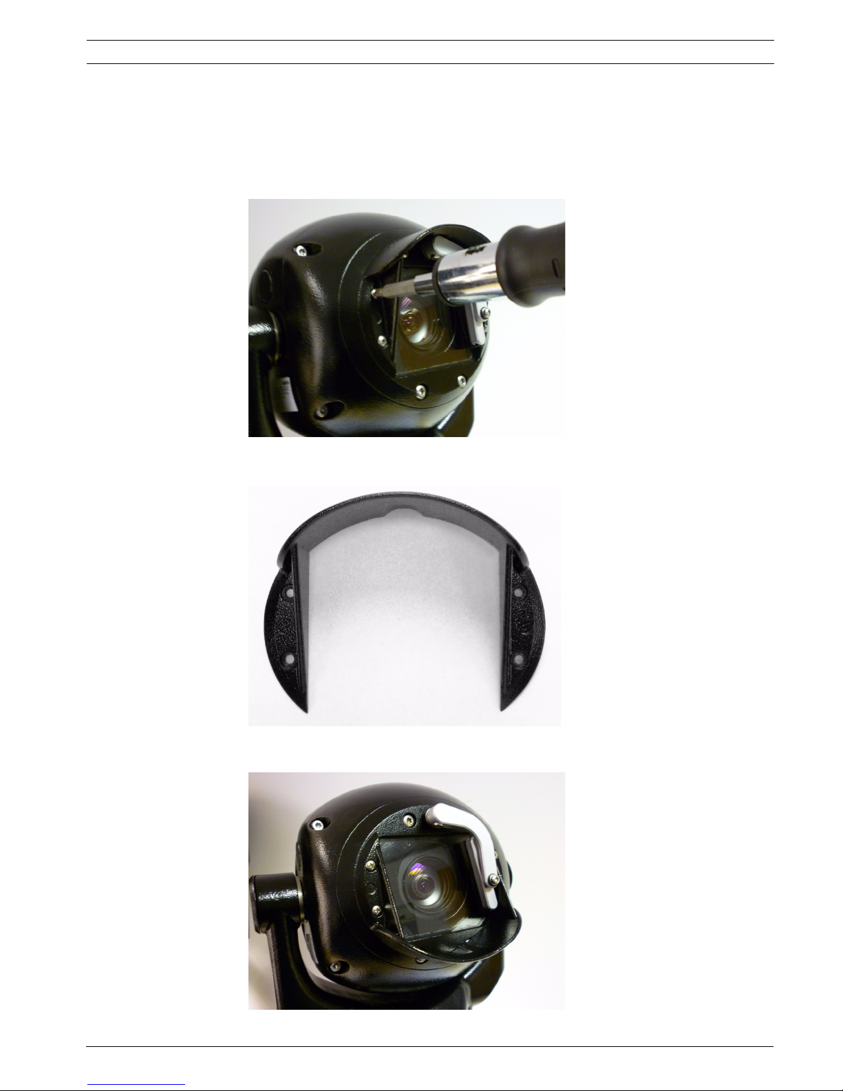
4.2 Adjusting the Rain Shield for Inverted Operation
The upright unit can be mounted either with the camera ball up or down.When inverted,
reverse the rain shield to provide weather protection for the window glass by following these
steps:
1. Remove the 4 of M3 x 6 screws fixing the rain shield to the face of the camera.
Figure 4.9 Remove screws
2. Reverse the rain shield.
Figure 4.10 Reverse rain shield
3. Reattach the rain shield to the camera face.
Figure 4.11 Inverted rain shield
 Loading...