


ce 120M
Operating Instructions
--
I
4 5
Version 102
BOSCH
Automation
ce 120M
Operating Instructions
1070 073 435-102 (92.03) GB
Reg. Nr. 16149-03
© 1991
by Robert Bosch GmbH,
All rights reserved, including applications tor protective rights. Reproduction or handing over to third parties are subject to our written permission.
Discretionary charge 20.- DM

@ BaSCH |
Table of contents |
ce 120 M |
|
Flexible Automation |
Operating Instroctions |
||
|
|||
|
|
|
Table of contents
New ehapters. whieh did not appear in CC 100 Mare marked with a "0" belore the page number.
General |
1-1 |
Prelaee |
1-2 |
Abbreviations . . . . . . . . . . . . . . . . . . . . . . . . . . . . . . . . . . . . . . . . . . . . . . . . . . . . . . . . . . . . . . . . . . . . . . |
.. 1-2 |
Control panel . . . . . . . . . . . . . . . . . . . . . . . . . . . . . . . . . . . . . . . . . . . . . . . . . . . . . . . . . . . . . . . . . . . . . ... |
1-3 |
Contral elements 01 the panel. . . . . . . . . . . . . . . . . . . . . . . . . . . . . . . . . . . . . . . . . . . . . . . . . . . . . . . . |
.. 1-4 |
Manual panel . . . . . . . . . . . . . . . . . . . . . . . . . . . . . . . . . . . . . . . . . . . . . . . . . . . . . . . . . . . . . . . . . . . . . . |
.. 1-6 |
Control elements 01 the manual panel .. . . . . . . . . . . . . . . . . . . . . . . . . . . . . . . . . . . . . . . . . . . . . . . . |
.. 1-7 |
Sereen layout in "GOM MACHINE" |
1-9 |
Operating instruetions |
, 1-10 |
Symbols used |
1-10 |
Initial display |
|
|
2-1 |
Memory general |
|
|
2-2 |
Part programs or cyeles |
|
2-3 |
|
Editing. inputting and outputting part programs |
|
2-3 |
|
Editing a program line |
|
|
2-5 |
Deleting a program line |
|
2-6 |
|
Searehing for eharaeter strings/inserting a text |
|
2-6 |
|
Example: Searehing lor program end/M30 |
|
2-7 |
|
Example: Inserting a !ine . . . . . . . . . . . . . . . . . . . . . . . . . . . . . . . . . . . . . . . . . . . . . . . . . . . . . |
. . . . .. |
2-8 |
|
Renaming a program |
|
|
2-9 |
Deleting a program |
|
|
2-10 |
PROTECTION ON/OFF |
'" |
|
2-10 |
Units 01 measurement |
(ineh/metrie) |
, 2-11 |
|
Notes on units 01 measurement |
, 2-11 |
||
Copying a program |
|
, 2-12 |
|
Converting programs to eyeles . . . . . . . . . . . . . . . . . . . . . . . . . . . . . . . . . . . . . . . . . . . . . . . . . . . |
. . . .. |
2-13 |
|
Renumbering programs |
|
|
2-14 |
CYCLES |
|
|
2-15 |
Drilling and eontour eyeles |
2-16. 2-17 |
||
Example 01 drilling eyeles |
|
2-18 |
|
Contour eyeles |
|
|
2-20 |
Tables |
|
|
2-21 |
Editing the tool table |
|
: |
2-21 |
Zero shiltlvariables table |
" |
2-24 |
|
Variables |
|
0 |
2-24 |
Input/output functions |
|
2-25 |
|
Example: inputting an individual part program |
|
2-26 |
|
Example: outputting programs/eyeles/tables |
|
2-27 |
|
Formatleheeksum |
|
|
2-28 |
1. DFS program header |
|
2-28 |
|
2. Inputting/outputting the eheeksum |
|
2-29 |
|
Cont. - 1

@ BOSCH |
Table of contents |
ce 120 M |
|
Flexible Automation |
Operating Instructions |
||
|
Initial display .......................................... |
• |
............................. 3-1 |
Basic funetions |
|
3-1 |
Approaehing referenee points(s) " |
|
3-2 |
Manual mode |
|
3-3 |
Exampie: traversing axes manually |
|
3-3 |
Example: entering a block . . . . . . . . . . . . . . . . . . . . . . . . . . . . |
. . . . . . . . . . . . . . . . . . . . . . . . . . . . .. |
3-6 |
Teach in |
|
3-7 |
Seleeling the unit of measurement inch/metrie |
|
3-12 |
Initial display |
|
4.,.' |
Basic funetions |
|
4 |
Automatic execution of programs/cycles |
|
4-" |
Procedure before NC Start |
|
4-2 |
Automatie exeeution in normal mode/dry run/rapid leed |
|
4-3 |
Seleeting/editing the step size ................................................. |
• |
....... 4-4 |
Aetivating a stop point |
|
4-5 |
Seleeting an NC block direetly/defining braneh destinations |
|
4-6 |
Seleeting the milling eonditions |
|
4-6 |
Calling CPC test |
|
4-8 |
Seleeting the start point |
|
4-8 |
Departure/re-entry during automatie mode |
|
4-8 |
Proeedure |
|
4-9 |
Procedure after NC Start |
|
4-10 |
Tables |
|
4-11 |
DRIP FEEDING (automatic mode via interface) |
|
4-12 |
SeleC1ing drip feeding |
|
4-12 |
Simulation |
|
4-14 |
Initial display |
|
|
5-1 |
|
Options . . . . . . . . . . . . . . . . . . . . . . . . . . . . . . . . . . . |
. . . . . . . . . . . . . . . . . . . . . . . . . . . . . . . . . |
. . . . . . . |
. . 5-1 |
|
Machine status functions ..... . . . . . . . . . . . . . . |
. . . . . . . . . . . . . . . . . . . . . . . . . . . . . . . . . |
. . . . . . . |
. . 5-2 |
|
Meaning of machine status functions |
|
|
5-4 |
|
NC 110 status |
|
|
5 |
-5 |
Errors and mesaages |
|
|
5 |
-6 |
Axis displays |
|
|
5 |
-7 |
Meaning ofaxis display functians |
|
|
: . 5 |
-7 |
Status table . . . . . . . . . . . . . . . . . . . . . . . . . . . . . . . |
. . . . . . . . . . . . . . . . . . . . . . . . . . . . . . . . . |
. . . . . . . |
. . 5-8 |
|
PIC/PC displays |
|
|
5-10 |
|
Calling up search functians |
|
|
5-11 |
|
Seleeting time/counter tables and 110 f1ags |
" |
'" |
5-12 |
|
I/Ollag8 |
|
|
5-13 |
|
Calling up trigger functians |
|
|
5-14 |
|
Service lunctions |
|
|
5-' |
|
Logbook |
|
|
5-1 i |
|
Cant. - 2

@ BOSCH |
Table of contents |
ce 120 M |
|
Flexible Automation |
Operating Instructions |
||
|
|||
|
|
|
Displaying logbook ...................................... |
|
|
•........................ |
|
5-17 |
|
Outputting logbook . . . . . . . . . . . . . . . . |
. . . . |
. . . . . . . . . . . . . . |
. . . . • . . . . . . . . . . . . . . . . . . . |
. . . •. |
5-18 |
|
Setting the clock and date display ........................ |
|
|
•...•..................... |
Q 5-19 |
||
Selecting the language ............ |
•............................................ |
|
|
•. 5-19 |
||
Selecting ON UNE PIC/ON UNE PANEL/ON UNE DNC .................................... |
|
•. 5-20 |
||||
Interface ....... |
•......................... |
|
•....................... |
•.•...•....... |
•... |
5-20 |
DRIP FEEDING |
|
|
|
|
|
5-21 |
Buffer size .............................................. |
|
|
|
•......................... |
• |
5-22 |
Block offset ..•.•................................................................. |
|
|
|
• |
5-22 |
|
DNC INTERFACE with LSV 2 protocol .......................... |
|
|
•....................... |
|
5-24 |
|
MTB service/resetldelete ...................................... |
|
|
•...................... |
|
5-24 |
|
Softkey architecture for machine tool builder ...... |
•.............. |
•..................... |
• |
5-25 |
||
Reset and delete |
|
|
|
|
|
5-25 |
Control reset |
|
|
|
|
|
5-25 |
Cont. - 3
~ BOSCH |
ce 120 M |
1 Introduction |
|
Flexible Automation |
Operating Instructions |
General
ce 120 M
Continuous path controi for driiling and milling machines and small machining centres with 3 - 4 axes and a main spindie .
Continuous path control for wood machining. automatie drilling and surface mil-
Iing applications.
Modular continuous path control for automated systems with max. 5 axes or with 4 axes and a main spindie .
Continuous path contral for special
cellular plastic. flame. stone and glass cutting applications, drilling / milling / scribing PCBs.
Programming to DIN 66 025 / expanded to include new graphie and computing functions (CPC) and customer-specific cycles.
|
|
|
|
|
|
|
|
|
|
|
|
|
|
|
|
|
|
|
|
|
|
|
ce 120 M |
|
|
|
{I |
BOSCH |
|
|
|
|
|
|
|
|
|
|
|
|
|
|
|
|
CD CD CD |
CD |
|
|
|
|
|
|
|
|
|
|
|
|
|
|
|
|
|
|
|
||
|
|
|
|
|
|
|
|
|
|
000000 |
00 |
|
|
|
|
|
|
|
|
|
|
|
|
|
|
|
0 |
00 |
|
|
|
|
|
|
|
|
|
|
|
|
|
|
|
00000 |
00 |
|
|
|
|
|
|
|
|
|
|
|
|
|
|
|
0000 |
00 |
|
|
|
|
|
|
|
|
|
|
|
|
|
|
|
0000 |
00 |
|
|
|
|
|
|
|
|
|
|
CD CD CD CD CD |
0 |
00000 |
00 |
|
|
|
|
||||
|
|
|
|
|
|
|
|
|
|
|
|
|||||
|
|
|
|
|
|
|
|
|
|
|
|
|
|
|
|
|
|
|
|
|
|
|
|
|
|
|
|
|
|
|
|
|
|
|
|
|
|
|
|
|
|
|
|
|
|
|
|
|
|
|
|
|
|
|
|
|
|
|
|
|
|
|
|
|
|
|
|
1 - 1

(@ BOSCH |
1 Introduction |
ce 120 M |
|
Operating Instructions |
|||
Flexible Automation |
|
||
|
|
|
Preface
The operating instructions only apply to software versions.2 850.
The control unit features 4 group operating modes (GOM). which can be selected with the symbols in the upper right hand corner of the control panel (see page 1-3).
MEMORY
MACHINE
[2]
~
Chapter 2
Chapter 3
AUTOMATIC |
[2] |
Chapter 4 |
(execution of |
||
prograrn) |
@] |
|
INFO |
Chapter 5 |
These GOMs will be described in the following chapters, and iIIustrated with examples.
In the "INTRODUCTION" chapter o the control panel,
o the control elements of the panel, o the manual panel,
o the control elements of the manual panel and o the screen layout
of the CC 120 M will be briefly outJined, instructions on use will be provided and the symbols used explained.
Please refer to the specialised index at the end of the manual for individual terms.
Abbreviations
BAUD |
Transmission rate (baud rate) in bits/sec |
CNC |
Computerized Numerical Contral |
OCR |
Digital Cassette Recorder |
DFS |
Define Store Program |
DNC |
Direct Numerical Control |
110 |
InputlOutput |
GOM |
Group Operating Mode |
Kbyte |
1024 bytes |
LSV |
Procedure to secure cables |
MP |
Machine Parameters |
Ne |
NumericaJ Control |
P |
Part program |
Pie |
Programmable Interface Controller |
RAM |
Random Access Memory |
SK |
Softkey |
F |
Feed |
MTB |
Machine T001 Builder |
1 - 2

(§ BOSeH |
1 Introduction |
ce 120 M |
|
Operating Instructions |
|||
Flexible Automation |
|
||
|
|
|
Control panel
|
|
|
|
Bracketed tunetions |
|||
|
|
|
|
(secondary functlon) |
|||
|
I<:a I |
|
Delete key |
|
|||
Service Information |
+ ~-- |
|
|
||||
Automatie executlon of programs I:J I |
~ |
|
|
|
|||
Dlrect machine mode |
------I[[t] l |
~ |
|
|
|
|
|
|
|
|
|
|
|
||
Memory mode |
[2] |
|
|
|
|
|
|
|
|
|
|
|
|
||
|
|
|
|
|
|
|
|
Softkeys
Meanlng varies depending on operating mode and status. There are several softkey levels
which can be selected consecutively,
Page back key ®
"R" can be used to
preselect the previous softkey level.
Axis addresses and |
|
|
Space key |
computing functions |
|
ENTER |
|
|
|
|
|
|
|
key |
SHIFT: enter |
|
|
|
|
CPC: enter |
|
|
upper functlon |
|
|
|
|
upper function |
|
|
|
|
|
Additional characters |
|
Computing and root functions |
|
|
|
Additional and auxiliary functions |
|
|
|
|
|
|
|
Digits I branches
ICPC test tunetions)
1 - 3

@ BaSeH |
1 |
Introduction |
ce 120 M |
||
Flexible Automation |
Operating Instructions |
||||
|
|
||||
|
|
|
|
|
|
Control elements of the panel
Note:
Dual-assignmenl keys have 2 funelions. whieh are selecled with eilher Ihe
ISH'FTI key (for leiters) or Ihe ICPC Ikey (for eompuling funclions). Le.
Press onee: seleel upper funelion.
Press Iwiee: reselecl original funetion.
ISH'FTI SHIFT: |
seleel upper leller |
ICPcl CPC: |
selecl upper compuling funelion |
Explanation of functions
Deseriplion of funelions performed by Ihe IwO rows of keys on Ihe righl hand
~
side of Ihe conlral panel (-+ see page 1-3) which are selecled with the c:::.J key:
eTI~ - Bracketed funclions (secondary) Leiters land L
EZlEtJ - Leiters B,J,O,P
IUKIIC~1_Leiters U.K,C,N
~~ - Leiters H.A,D - &: used only for word processing
~~ - Leiters Q. v. W, - $: branching
-SHIFT key: see above
-Space key: blank spaee
1 - 4

@ BOSCH |
1 |
ce 120 M |
Introduction |
||
Flexible Automation |
|
Operating Instructions |
|
|
|
Description of the functions performed by the row of keys on the left hand side of the control panel which are selected wlth the CPC key :
 - Computing functions for addition and subtraction - Letters G and X
|
- |
Computing functions for division and multiplication |
|||
|
- Letters Y and Z |
||||
ISI~llc~1 |
_Sine and eosine funetions |
||||
|
- |
Letters |
Fand |
M |
|
IA~GIIS~RI |
_Are tangent and root funetions |
||||
|
- |
Letters |
T |
and |
S |
|
- |
Equals sign, - Letter E |
|||
|
- |
TST: used for eonditlon register (CPC test funetions ! |
|||
|
-+ see Programming Manual CC t 20 M P. No. 4257) |
||||
|
- |
letter R |
|
|
|
. Numeric keypad |
|
|
|
||
IB~EIIB~lla~ol |
- |
Digits |
0 - 9 |
||
|
|
|
|||
|
|
|
- |
Parametric functions |
|
|
|
|
- see Programming Manual CC 120 M P. No. 4257. |
||
|
|
|
- BGE. BlE. BEQ. BNE. BlT. BGT: eonditional |
||
|
|
|
|
branches |
|
|
|
|
- |
BSR. BRA: uneonditional branehes |
|
|
|
|
- |
TRF: load ZS table or retrieve values from ZS |
|
|
|
|
|
table |
|
|
|
|
- |
DEC: deerement value |
|
|
|
|
- |
CPC key: see page 1-4 for explanation |
|
- Param. funetion COR: load tool memory
-Decimal point
-Param. funetion INC: Increment value
-Minus sign
-Delete key (dele1es the eharaeter in front of the cursor)
- ENTER key
1 - 5
@BOSeH
Flexible Automation
Manual panel
1 Introduction
ce 120 M
Operating Instructions
Front view
|
|
Customer keypad FI - FI5 |
|||
Electronlc |
handwheel |
|
|
|
Re-entry |
|
Emergency stop |
||||
|
|
Feed mode |
button |
|
|
|
|
|
|||
|
|
Distance to |
|
|
|
|
|
|
|
|
|
|
|
|
go key \ |
|
|
|
|
|
|
|
|
|
|
|
|
|
|
|
|
|
|
|
|
|
|
|
|
|
|
|
E1EJEJDEJE1E1E1E1EJ |
\0 |
|
|
|
|
||
|
EJEJEJEJEJ |
E11IJ- |
|
|
|
|||
|
||||||||
== |
= |
Eill:HBIB |
|
|
|
|
||
""'"' |
|
== |
|
|
|
|
||
|
|
|
|
|
|
|||
|
|
|
|
|
|
|
|
|
|
Axis selectlon swltch |
|
Start key |
|
|
|
|
|
|
|
|
|
|
|
|
|
|
|
|
|
|
Stop key |
|
|
|
|
100%-keys tor spindie speed, feedrate Jog keys |
|
|
|
|
||||
|
|
|
|
Departure |
||||
|
|
|
|
trom |
||||
|
|
|
|
contour |
||||
Functions
Potentiometer and 100%-key:
The feedrate is set as a % at the potentiometer; the key renders the potentiometer inaetive (100%).
Potentiometer used in MACHINE and AUTOMATIC operating modes.
Customer keypad:
Operative in GOM MACHINE; the permanently stored manual input funetior and maehine tunetions are initiated by pressing one of the keys.
1 - 6
(§l BOSCH |
1 Introduction |
ce 120 M |
|
Operating Instructions |
|||
Flexible Automation |
|
||
|
|
|
Control elements of the manual panel
Electronic handwheel
|
|
|
The eleetronie handwheel is used to manually |
|||||
|
|
|
traverse the axes. |
|
|
|
||
|
|
|
|
|||||
|
|
|
Set the axis to be traversed |
|
|
|
|
|
|
|
|
via the seleetion switch. |
|
|
|
|
|
|
|
|
|
|
|
|
|
|
|
|
|
Set rotary switch to handwheel lor selecting |
|||||
|
|
|
traversing mode (see below). |
|||||
|
|
|
The leedrate is determined by the leed |
|||||
|
|
|
||||||
|
|
|
potentiometer setting and the handwheel |
|||||
|
|
|
speed. |
|||||
|
|
|
(Speed is indicated on panel) |
|||||
|
Feed potentiometer (0 - 120 %) and 100%-key |
|||||||
|
|
|
Used in GOM MACHINE and AUTOMATie |
|||||
|
|
|
||||||
|
|
|
The 100%-key is only operative when the leed |
|||||
|
|
|
potentiometer is set between 80 and 120%. |
|||||
|
0% ANV' 120% |
|
When the 100%-key is actuated. the |
|||||
|
|
|
100% leed value indieated on the panel flashes; |
|||||
|
|
|
this means that the leedrate is always 100% |
|||||
|
|
|
irrespective 01 the value seleeted via the |
|||||
|
|
|
potentiometer. |
|||||
|
|
|
This ean be cancelled by pressing the 100% |
|||||
|
|
|
key once again: the 100% display ceases to flash |
|||||
|
|
|
and the selected leed value is valid. |
|||||
Spindie potentiometer (50 - 150%) and 100%-key
atu
50% @) 150%
See leed potentiometer lor instructions
The 100%-key is inactive il the spindie potentiometer setting < 80% or >120% (otherwise abrupt speed changes could oeeur).
Rotary switch lor selecting traversing mode
IWo/' I Feed with jog keys
I'V'\.o I Rapid leed with jog keys
~Feed with eleetronic handwheel
Selection 01 various incremental leed rates (1 to 10 000 steps)
Feed START by pressing the jog keys.
1 - 7
@ BOSeH |
1 |
Introduction |
ce 120 M |
|
Flexible Automation |
Operating Instmctions |
|||
|
|
|||
|
|
|
|
Customer keypad
Customer keys F1-F15: Ireely assignable via cycle no. 78
First 15 executed in blocks described in cycle 78
FunClion keys lor PIC input signals
A machine parameter determines the assignment 01 customer keys with NC or
PLC lunctions.
Axls selection switch
The respective axis to be traversed X. Y, Z, or E is set with the axis selection switch.
The axes are traversed via jog keys or the electronic handwheel.
EMERGENCY OFF BUTTON
Function keys
Jog keys:
[!]
c:J
~
~
~tIjll
II[D~
Positive traversing direction
Negative traversing direction
Departure from contour
|
only operative in |
} |
GOM AUTOMATIC |
(see P.4-9) |
|
Re-entry contour |
|
Stop key |
|
Start key |
|
BI
Display 01 distance to go
1 - 8

~ BOSCH |
1 Introduction |
ce 120 M |
|
Operating Instructions |
|||
Flexible Automation |
|
||
|
|
|
Screen layout in GOM I([iJJ I
(when "MANUAL INPUT" or "TEACH IN" are active)
|
|
|
Selected axls display: |
|||
|
|
|
COMMAND POSITION |
|
Posltional data |
|
|
|
|
||||
|
|
|
LAG |
|
|
|
|
|
|
MACHINE POSITION |
|
|
(G lunctlons) |
|
|
|
INDICATION OF |
|
|
|
ln-position symbol |
|
DISTANCE TO GO |
|
|
INCH/METRIC |
|
|
|
Error displays |
|
|
Actlve |
|
|
Sub-mode |
|
Current unlt |
|
group operating mode |
|
|
|
|
|
|||
|
(actlve data block) |
|
|
|
||
|
|
Inch (I). |
met |
|
|
|
|
|
|
|
|
||
|
|
|
|
|
|
|
|
|
|
|
|
|
|
|
|
|
|
|
|
|
|
|
|
|
|
OIO() |
|
- |
t:C:o:M::M=A~NrD=P~O~S~I~T~IO~N=;;-_jllnMI |
|
t |
||||
|
|
|
|
S |
|
|
|
|
|
Reference line |
|
Current spindie |
|
|
|
|
Tool number |
|
speed (0-150%) |
|
|
|
|
||
with cursor |
|
|
|
|
|
|
(T No.) |
|
Current feedrate |
|
|
|
|
|
|
|
|
|
|
|
|
|
|
|
|
|
|
|
Feed |
|
|
|
|
|
|
|
|||
|
|
programmed teedrate |
|
potentiometer cr |
|||
|
|
||||||
Function cr |
|
|
|
100%-key |
|||
|
|
|
|
|
|
||
softkey window |
4th axis |
||||||
(altemating 1 |
|
|
|||||
|
|
(optionai) |
|||||
|
|
|
|
||||
1 - 9

@ BOSCH |
1 |
Introduction |
ce 120 M |
|
Flexible Automation |
Operating Instructions |
|||
|
|
|||
|
|
|
|
Operating instructions
1.The CC120M leatures live soltkeys. whieh are situated under the sereen. Various lunetions are assigned to these keys. Depending on the eommand status. the possible lunetions are indieated at the bOllom 01 the sereen, direetly above the soltkeys, The eontrol sequenee is determined via the soltkeys onee a GOM has been seleeted,
2.Eaeh new key assignment is designated as a soltkey level.
3.There are several soltkey levels in eaeh GOM, These are seleeted eonseeutively. The next soltkey level is seleeted by aetuating the respeetive softkey.
4, The funetions are seleeted (by pressing the respeetive soltkey in bold) line by line (soltkey strips). Irom top to bOllom and lram left to right.
5.It is possible to return to the previous level by aetuating the page bat? key ® (see page 1-3).
6.The 11 ENTERII key must be pressed to store eaeh digital value input.
7.II a different GOM is seleeted without lirst returning to the basie level. the former GOM designation Ilashes in the upper right hand eorner 01 the sereen, indieating that it is still aetive. The GOM is ehanged by returning to the basie level and seleeting the new GOM. The exeeption to this is "AUTOMATIC" whieh ean seleeted direetly from GOM MEMORY.
8.II neeessary. the eontrol unit will provide the following information during
AUTOMATIC |
or MACHINE mode: |
|
- |
WARNING |
it is possible to eontinue automatie mode |
- |
ERROR automatie mode has been interrupted, |
|
The error message is indieated in GOM INFO
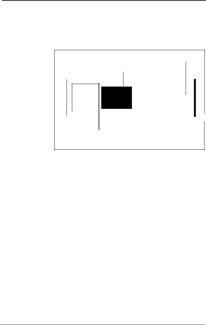
S Actuate functlon key
===~======: Softkey highlighted:
|
|
function ls active |
|
'- |
) Softkey not highlighted: |
||
>functlon terminated or not active. |
|||
|
|
Enter numeric vaiue |
|
|
|
Page back |
-+ see page 1-4 |
1 - 10

@ BOSCH |
Memory [2] |
ce 120 M |
|
Operating Instructions |
|||
Flexible Automation |
|
||
|
|
|
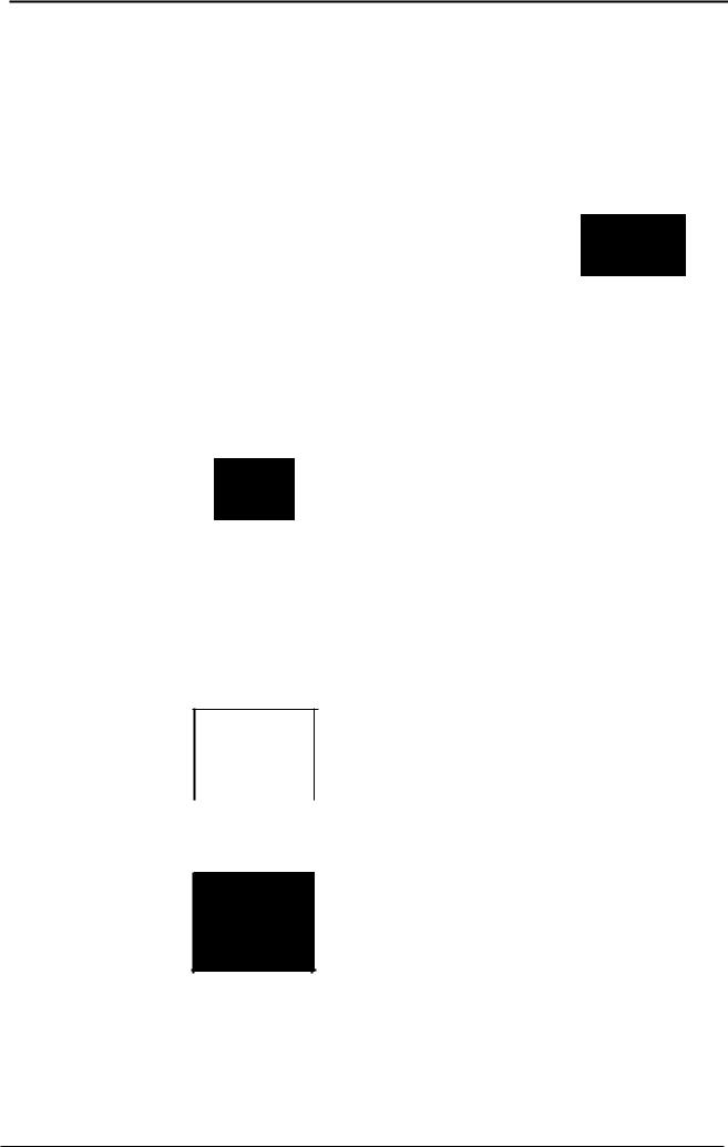
GOM MEMORy[2]
The following initial display appears after selecting GOM MEMORY via the
[2] key:
Initial display
|
|
|
|
MEMORY |
|
BOSCH |
CC 120 M |
||
to |
99 tools (Tl |
> •• T99) |
|
|
to |
6 zero shifts |
(G54 |
... G60, G160) |
|
to |
827 CPC variables |
(V1 |
.. V99, VOA .. VCZ, VAA .. VR2) |
|
to |
69 Cycles |
|
|
|
VARIABLES
Calling |
|
|
Part programs or cycles |
Page |
2-3 |
Tables |
Page |
2-21 |
(Tool. zero shift (ZS) |
|
|
and variable tables) |
|
|
Input and output functions (data interface) |
Page |
2-25 |
2 - 1

@ BOSCH |
Memory [2] |
ce 120 M |
||
Operating Instructions |
||||
Flexible Automation |
|
|||
|
|
|
|
|
MEMORY general
Memory for input and editing of:
part programs (max.999 999 999/limited by memory capacity) • max. 69 cycles,
max. 48 tool compensations (99 tools optional) , parameter table for max. 48 tools (99 tools optional) , tool Iife,
max. 6 zero shifts per axis and 2 additional zero shifts
max. 1035 CPC variables, 208 of which are reserved for MTB.
Input of information via:
keypad (EDIT) and
interfaces V24/20 mA (port 1) and/or V24 (port 2).
Output of information via:
interfaces V24/20mA (port 1) and/or V24 (port 2).
Types of protection
Unauthorised access (read, write and delete) can be prevented via the softkeys. The execution of cycles is always authorised.
Types of protection are indicated as folIows:
RWEO |
Read, Write, Execute, Delete authorised |
|
|
RE |
Read and execute authorised |
|
|
|
|
~-'---~ |
|
|
, By actuating the SK |
PROTECTION |
(see P.2-10). |
|
ON/OFF |
||
E |
Execution only authorised |
|
|
o The "E" type of protection can only be activated in GOM INFO. The codeword only for cycles must be entered via "MTB SERVICE" .
o Apart program must first be converted into a cycle (see page 2-13) order to select the read protection function.
2 - 2

I@ BOSCH |
Memory [2] |
ce 120 M |
|
Operating Instructions |
|||
Flexible Automation |
|
||
|
|
|
Part programs or cycles
o Part programs/cycles can be
- edited (edit. insert, regenerate or search for texts),
-input and output.
-deleted,
-renamed,
-copied,
-or renumbered.
o Part programs can be
- converted to cycles (but not visce versa).
--+ For information on c y c 1e s see page 2-15.
Editing, inputting and outputting part programs |
|
When the SK I PROGRAMS I |
is actuated, the programs in the memory are |
listed. |
|
If apart program was active prior to this, the program number (cursor flashes)
|
is indicated |
(the "P1" part program - GEAR, in this case): |
||||
|
|
|
|
|
|
|
|
|
|
|
|
|
|
|
TOOLS |
I ZERO POINTS r VARIABLES I PROGRAMS I CVCLES |
|
|||
|
|
|
|
|
|
|
|
|
|
|
|
|
|
|
|
|
|
|
|
|
|
|
|
|
|
|
|
|
|
|
|
|
|
|
|
|
|
|
|
|
|
The part program GEAR (cursor flashes) can be input or output by actuating the
SK I INPUT I or I OUTPUT I.
--+ See INPUT/OUTPUT FUNCTIONS on page 2-25 for operating sequence.
The next page is called there are more than 10
up by actuating the SK I |
~;~~ |
I (only when |
programs in the memory). |
|
|
A different program can be calied up by deleting the old program no. (DELETE KEY) and entering the new number (cursor does not flash).
2 - 3
@l BOSeH
Flexible Automation
Memory C8 |
ce 120 M |
|
Operating Instructions |
||
|
Example: editing apart program
PROG. NO. |
I _~ |
~ ENTER ~ |
or NAME |
. ~ |
|
A DIFFERENT FILE VIA RED DELETE KEY
COMMANDS T NEXT I EDIT I INPUT I OUTPUT PAGE
A different part program is selected by deletlng the last part program to have been called up (actuate delete key) and entering the name or number of the new one.
When a program has been selected (e.g. "HOLE PATIERN"/prog. no. 4), the
program start ("N1 - N4") Is dlsplayed when the SK I EDIT I Is actuated, The name and number of the active program appear In the prograr header.
The cursor is positloned at the start of the first line:
MRWED MEMORY
I |
|
PROGRAM START |
I;:;:~.: |
>Nl |
GO |
N2 |
X10 |
The cursor can be moved vertlcally by simultaneously actuating the IlsCROLyl
and ~or [[Z]] keys. The cursor can be moved horizontally in the reference line by pressing the ~or iC1:J] keys.
2 - 4

@ BOSCH |
Memory [2] |
ce 120 M |
|
Operating Instructions |
|||
Flexible Automation |
|
||
|
|
|
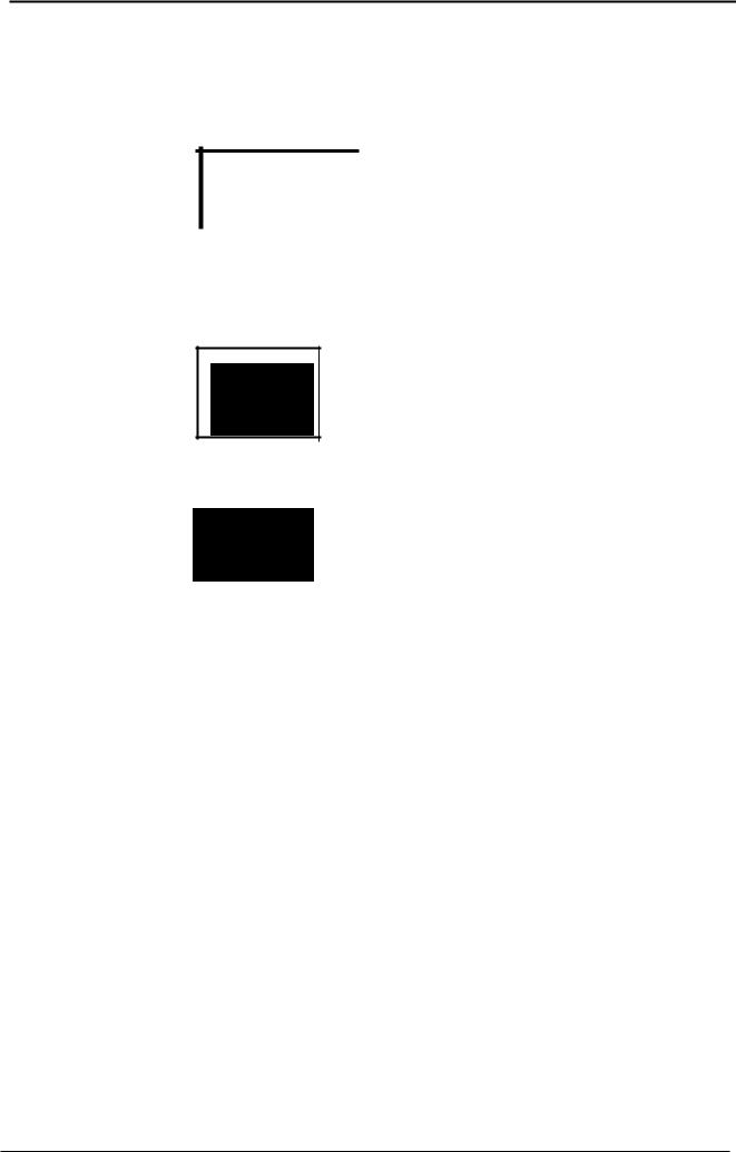
Editing a program line
When the program has been called up and the "EDIT FUNCTION" selected, the cursor is moved to the start of the line to be edited ("N3") using the cursor keys. -+ see page 2-4.
Example: Editing a character |
|
|
|
||||
Editing line "N 3" |
("X10"): the new block is "Y10": |
||||||
|
|
|
|
|
MRweo |
|
|
|
|
|
|
4 HOLE PATTERN |
MEMORY |
|
|
|
|
PROGRAM START |
|
|
|
||
|
Nl |
GO |
- |
|
|
|
|
|
>N3 |
Xl0 |
Yl0 |
|
|
|
|
|
N2 |
Xl0 |
|
|
|
I |
|
};:~~ |
N4 |
Z10 |
|
|
|
|
|
~~j |
N5 |
Gl |
X100 |
|
|
|
|
|
N6 |
Yl00 |
|
|
|
|
|
1--N3---.-,0------------------ |
|
||||||
|
|
|
|
|
|
|
|
The "EDIT" function is active (highlighted).
Procedure:
I N3 |
|
|
Use [I2JI to move the cursor to "1",'which is to |
||
|
|
|
X10 |
||
|
|
|
|
|
the right of the character to be deleted ("X"). |
|
|
|
|
|
Press the delete key. The character to the left of the |
|
|
|
|
|
cursor is deleted. |
|
|
|
|
|
|
|
|
N3 |
10 |
|
Enter "Y" via keypad. |
|
|
|
|
|
|
|
|
N3 |
Y10 |
||
|
|
|
|
|
The edited text appears in the line "N 3" after the |
|
|
|
|
|
|
~ENTER ~ key is actuated:
2 - 5

@ BOSCH |
Memory [2] |
|
|
|
ce 120 M |
Flexible Automation |
|
Operating Instructions |
|||
|
|
|
|
|
|
|
|
|
|
|
|
Any number of characters in a block can be edited, deleted or inserted in this manner.
Deleting a program line
The entire !ine to the right of the cursor (including the character at which the cursor is positioned) is deleted by actuating the
11 SHIFT ~ -+ I# I -+ 11 ENTER ~ keys.
Searching for character strings
It is possible to search for character strings in "edit" mode. Select the appropriate softkeys and enter the character string (this is indicated in the reference !ine).
The cursor jumps to the line where the character strlng first occurs when the ~ENTER ~ key is actuated.
2 - 6

@ BOSeH |
Memory [2] |
ce 120 M |
|
Operating Instructions |
|||
Flexible Automation |
|
||
|
|
|
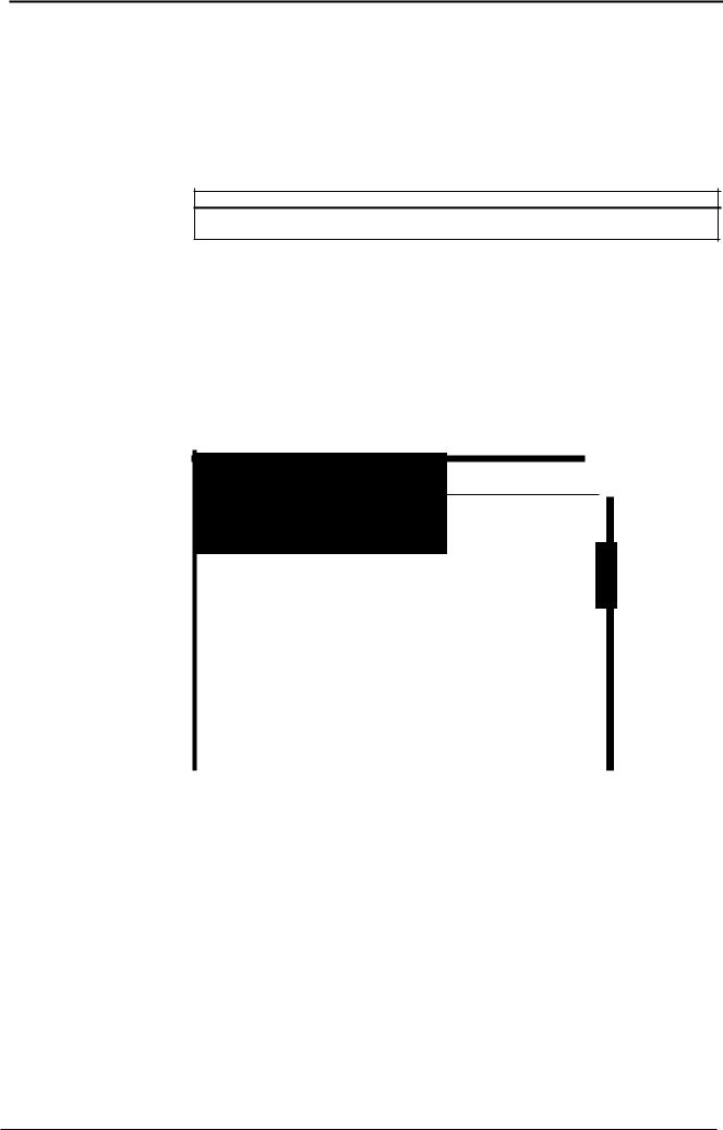
Example: Search tor program end/M30
In praclice il is otlen the case that a new line is required at the program end.
Position the cursor at "M30":
PROGRAM SELECTION
COMMANDS I |
PAGE |
I |
EDIT |
I |
INPUT |
I OUTPUT |
NEXT |
|
|
|
|
|
|
- |
|
|
|
|
|
|
|
|
|
|
|
SEARCH + |
|
|
SCROLL |
- |
|
|
EDIT |
|
|||||
|
CVCLES |
|
|
|
|
|
|
|
|
INSERT |
|
|||
|
|
|
|
|
|
|
|
|
|
|
||||
|
|
|
|
|
|
|
|
|
|
|
|
|||
|
ENTER CHARACTER STRING? |
|
|
|
|
|
|
|
|
|
|
|||
|
|
I |
MILLING |
I |
|
I |
DRILLING |
I |
CONTOUR |
|
||||
|
|
CVCLES |
|
|
|
CVCLES |
DEFINITIONS |
|
||||||
|
|
|
|
|
|
|
|
|
|
|
|
|
|
|
ENTER CHARACTER STRING? M30
__ I 1
The cursor jumps trom the 1st line 10 the last line "N 9":
Yl00 |
|
|
><200 |
,. |
|
X400 |
||
|
MOO
~!
L Important! ----------------------- |
' |
When searching tor block numbers (e.g. N 100). enler aspace betore the number ("N 100").
"NOT FOUND" will appear it the entered character string does not exisl.
2 - 7

@> BOSeH
Flexible Automation
Memory [2] |
ce 120 M |
|
Operating Instructions |
||
|
Example: Inserting a line |
|
|
|
|
|
|||
Insert a new line with the text "Y300" between |
lines" N S" (X400) and "N 9" |
|||||||
(M30/Program end): |
|
|
|
|
|
|
||
|
Move cursor to "N S" and actuate the |
SK |
I_-,-IN"ES::.~::;I~"T,-_I so that |
|||||
|
"INSERT" |
is highlighted. |
|
|
|
|
|
|
|
Enter the new fine "Y300" via keypad. " Y300 " appears in the relerence |
|||||||
|
fine: |
|
|
|
|
|
|
|
|
|
|
|
|
|
|
|
|
N+ |
Y300 |
I |
- |
|
|
|
- |
|
SEARCH + |
I |
SCROLL |
I |
|
||||
|
CYCLES |
|
|
|
|
|
||
|
|
|
|
|
|
|
|
|
The inserted fine appears between the fines "N S" and "N 9" as the block number "N+S" when the ~ENTER ~ key is actuated:
~j!~::~~~i%Wjt'l~jl::~'::~:~~~i!lWMlli~~:@NM&=~' |
|
J: :: |
I |
F~:: |
I |
11' |
----------------------- |
|
|
|
|
|
lf:~ |
N9 |
|
I |
I |
|
|
a SEARCH + I - |
LEOrt |
|
||||
i:I;li,t:~~~:1wim;;wH1#:m'i!i'wlf:'i!",l |
"il:;::~:<)1#Mm:::1!1!l%;~:::;iM |
|
||||
|
The part program, "P4" |
(HOLE PATIERN) is renumbered by actuating the |
||||
|
fR\ |
|
I |
RENUMBER |
I |
|
|
v |
key, 2 x "COMMANDS", and the SK '--------- |
' |
|||
(-+ see page 2-15). The block "N+S" is assigned the block number"N 9" and the last block "N 9" (M30) is assigned the block number "N 10".
The fines 01 the "P4" program will be renumbered the next time the "P4" program is selected. ("N 1"-"N 10").
2 - 8
 Loading...