


Antriebsund Steuerungstechnik
CC 220 M
Graphic programming
Operating instructions, Part 1 and Part 2
Version 101
Automationstechnik

CC 220 M
Graphic programming
Operating instructions, Part 1 and Part 2
1070 073 323-101 (92.01) GB
(V25)
E 1992
by Robert Bosch GmbH,
All rights reserved, including applications for protective rights. Reproduction or handing over to third parties are subject to our written permission.
Discretionary charge 40.– DM

Flexible Automation
Contents |
CC 220 M |
|
Operating instructions |
||
|
Contents
Graphic programming Part 1
Page
1.GENERAL
Summary of functions . . . . . . . . . . . . . . . . . . . . . . . . . . . . . . . . . . . . . . . . . . . . . . . . . . . . . . . . . . . 1–1 Notes, conventions . . . . . . . . . . . . . . . . . . . . . . . . . . . . . . . . . . . . . . . . . . . . . . . . . . . . . . . . . . . . . . 1–2 Input dialog, input format . . . . . . . . . . . . . . . . . . . . . . . . . . . . . . . . . . . . . . . . . . . . . . . . . . . . . . . . . 1–2 Function keys and softkeys . . . . . . . . . . . . . . . . . . . . . . . . . . . . . . . . . . . . . . . . . . . . . . . . . . . . . . . 1–3 Operating and softkey levels . . . . . . . . . . . . . . . . . . . . . . . . . . . . . . . . . . . . . . . . . . . . . . . . . . . . . . 1–3 Level return key . . . . . . . . . . . . . . . . . . . . . . . . . . . . . . . . . . . . . . . . . . . . . . . . . . . . . . . . . . . . . . . . . 1–4 Input confirmation . . . . . . . . . . . . . . . . . . . . . . . . . . . . . . . . . . . . . . . . . . . . . . . . . . . . . . . . . . . . . . . 1–4 Window technique . . . . . . . . . . . . . . . . . . . . . . . . . . . . . . . . . . . . . . . . . . . . . . . . . . . . . . . . . . . . . . . 1–4 Absolute/incremental values . . . . . . . . . . . . . . . . . . . . . . . . . . . . . . . . . . . . . . . . . . . . . . . . . . . . . . 1–5 Cursor keys . . . . . . . . . . . . . . . . . . . . . . . . . . . . . . . . . . . . . . . . . . . . . . . . . . . . . . . . . . . . . . . . . . . . 1–6 Angle input . . . . . . . . . . . . . . . . . . . . . . . . . . . . . . . . . . . . . . . . . . . . . . . . . . . . . . . . . . . . . . . . . . . . . 1–7 Coordinate input . . . . . . . . . . . . . . . . . . . . . . . . . . . . . . . . . . . . . . . . . . . . . . . . . . . . . . . . . . . . . . . . 1–8 Units of measurement . . . . . . . . . . . . . . . . . . . . . . . . . . . . . . . . . . . . . . . . . . . . . . . . . . . . . . . . . . . 1–9 Selection of a contour or contour section . . . . . . . . . . . . . . . . . . . . . . . . . . . . . . . . . . . . . . . . . . 1–11 Geometrical principles . . . . . . . . . . . . . . . . . . . . . . . . . . . . . . . . . . . . . . . . . . . . . . . . . . . . . . . . . . 1–19 Coordinate system . . . . . . . . . . . . . . . . . . . . . . . . . . . . . . . . . . . . . . . . . . . . . . . . . . . . . . . . . . . . . 1–19 Zero points and reference points . . . . . . . . . . . . . . . . . . . . . . . . . . . . . . . . . . . . . . . . . . . . . . . . . 1–21 Tools . . . . . . . . . . . . . . . . . . . . . . . . . . . . . . . . . . . . . . . . . . . . . . . . . . . . . . . . . . . . . . . . . . . . . . . . . . 1–24 Zero point offset . . . . . . . . . . . . . . . . . . . . . . . . . . . . . . . . . . . . . . . . . . . . . . . . . . . . . . . . . . . . . . . . 1–29
2.OPERATION
Graphic programming . . . . . . . . . . . . . . . . . . . . . . . . . . . . . . . . . . . . . . . . . . . . . . . . . . . . . . . . . . . . 2–1 Geometry . . . . . . . . . . . . . . . . . . . . . . . . . . . . . . . . . . . . . . . . . . . . . . . . . . . . . . . . . . . . . . . . . . . . . . 2–1 Working plan . . . . . . . . . . . . . . . . . . . . . . . . . . . . . . . . . . . . . . . . . . . . . . . . . . . . . . . . . . . . . . . . . . . 2–1 File . . . . . . . . . . . . . . . . . . . . . . . . . . . . . . . . . . . . . . . . . . . . . . . . . . . . . . . . . . . . . . . . . . . . . . . . . . . . 2–1 Data transfer . . . . . . . . . . . . . . . . . . . . . . . . . . . . . . . . . . . . . . . . . . . . . . . . . . . . . . . . . . . . . . . . . . . 2–1 Graphic display . . . . . . . . . . . . . . . . . . . . . . . . . . . . . . . . . . . . . . . . . . . . . . . . . . . . . . . . . . . . . . . . . 2–2 Magnifier . . . . . . . . . . . . . . . . . . . . . . . . . . . . . . . . . . . . . . . . . . . . . . . . . . . . . . . . . . . . . . . . . . . . . . . 2–2 Messages . . . . . . . . . . . . . . . . . . . . . . . . . . . . . . . . . . . . . . . . . . . . . . . . . . . . . . . . . . . . . . . . . . . . . . 2–2
Control panel . . . . . . . . . . . . . . . . . . . . . . . . . . . . . . . . . . . . . . . . . . . . . . . . . . . . . . . . . . . . . . . . . . . . 2–3 Input field . . . . . . . . . . . . . . . . . . . . . . . . . . . . . . . . . . . . . . . . . . . . . . . . . . . . . . . . . . . . . . . . . . . . . . 2–4 Screen display . . . . . . . . . . . . . . . . . . . . . . . . . . . . . . . . . . . . . . . . . . . . . . . . . . . . . . . . . . . . . . . . . . 2–6 Color tables . . . . . . . . . . . . . . . . . . . . . . . . . . . . . . . . . . . . . . . . . . . . . . . . . . . . . . . . . . . . . . . . . . . . . 2–7
Contents − 1

Flexible Automation
Contents |
CC 220 M |
|
Operating instructions |
||
|
Page
3. . GEOMETRY
Geometry input . . . . . . . . . . . . . . . . . . . . . . . . . . . . . . . . . . . . . . . . . . . . . . . . . . . . . . . . . . . . . . . . . . 3–1 Graphic working area . . . . . . . . . . . . . . . . . . . . . . . . . . . . . . . . . . . . . . . . . . . . . . . . . . . . . . . . . . . . 3–2 Coordinate origin . . . . . . . . . . . . . . . . . . . . . . . . . . . . . . . . . . . . . . . . . . . . . . . . . . . . . . . . . . . . . . . . 3–4 Description of the finished part . . . . . . . . . . . . . . . . . . . . . . . . . . . . . . . . . . . . . . . . . . . . . . . . . . . 3–7 External contour . . . . . . . . . . . . . . . . . . . . . . . . . . . . . . . . . . . . . . . . . . . . . . . . . . . . . . . . . . . . . . . . . 3–9
Creating the external contour . . . . . . . . . . . . . . . . . . . . . . . . . . . . . . . . . . . . . . . . . . . . . . . . . . . . . 3–9 Rectangle . . . . . . . . . . . . . . . . . . . . . . . . . . . . . . . . . . . . . . . . . . . . . . . . . . . . . . . . . . . . . . . . . . . . 3–10 Circle . . . . . . . . . . . . . . . . . . . . . . . . . . . . . . . . . . . . . . . . . . . . . . . . . . . . . . . . . . . . . . . . . . . . . . . . 3–11 Change, delete, confirm . . . . . . . . . . . . . . . . . . . . . . . . . . . . . . . . . . . . . . . . . . . . . . . . . . . . . . . . . 3–12 Contour blend . . . . . . . . . . . . . . . . . . . . . . . . . . . . . . . . . . . . . . . . . . . . . . . . . . . . . . . . . . . . . . . . 3–13 Elements of a contour blend . . . . . . . . . . . . . . . . . . . . . . . . . . . . . . . . . . . . . . . . . . . . . . . . . . . . . 3–16 Line . . . . . . . . . . . . . . . . . . . . . . . . . . . . . . . . . . . . . . . . . . . . . . . . . . . . . . . . . . . . . . . . . . . . . . . . . . 3–18 Arc . . . . . . . . . . . . . . . . . . . . . . . . . . . . . . . . . . . . . . . . . . . . . . . . . . . . . . . . . . . . . . . . . . . . . . . . . . . 3–20 Transition conditions for producing contour blends made up of several elements . . . . . . . 3–21 Defined contour blend elements . . . . . . . . . . . . . . . . . . . . . . . . . . . . . . . . . . . . . . . . . . . . . . . 3–24 Circle to line . . . . . . . . . . . . . . . . . . . . . . . . . . . . . . . . . . . . . . . . . . . . . . . . . . . . . . . . . . . . . . . . . . . 3–24 Line to circle . . . . . . . . . . . . . . . . . . . . . . . . . . . . . . . . . . . . . . . . . . . . . . . . . . . . . . . . . . . . . . . . . . . 3–31 Line to line . . . . . . . . . . . . . . . . . . . . . . . . . . . . . . . . . . . . . . . . . . . . . . . . . . . . . . . . . . . . . . . . . . . . 3–34 Circle to circle . . . . . . . . . . . . . . . . . . . . . . . . . . . . . . . . . . . . . . . . . . . . . . . . . . . . . . . . . . . . . . . . . 3–37 Undefined contour blend elements . . . . . . . . . . . . . . . . . . . . . . . . . . . . . . . . . . . . . . . . . . . . . 3–41 Circle to circle . . . . . . . . . . . . . . . . . . . . . . . . . . . . . . . . . . . . . . . . . . . . . . . . . . . . . . . . . . . . . . . . . 3–44 Circle to line . . . . . . . . . . . . . . . . . . . . . . . . . . . . . . . . . . . . . . . . . . . . . . . . . . . . . . . . . . . . . . . . . . . 3–47 Line to circle . . . . . . . . . . . . . . . . . . . . . . . . . . . . . . . . . . . . . . . . . . . . . . . . . . . . . . . . . . . . . . . . . . . 3–48 Input example . . . . . . . . . . . . . . . . . . . . . . . . . . . . . . . . . . . . . . . . . . . . . . . . . . . . . . . . . . . . . . . . 3–51 Start point selection . . . . . . . . . . . . . . . . . . . . . . . . . . . . . . . . . . . . . . . . . . . . . . . . . . . . . . . . . . . . 3–54 Input example . . . . . . . . . . . . . . . . . . . . . . . . . . . . . . . . . . . . . . . . . . . . . . . . . . . . . . . . . . . . . . . . 3–56 Closing the contour . . . . . . . . . . . . . . . . . . . . . . . . . . . . . . . . . . . . . . . . . . . . . . . . . . . . . . . . . . . . . 3–58 Rounding/chamfer . . . . . . . . . . . . . . . . . . . . . . . . . . . . . . . . . . . . . . . . . . . . . . . . . . . . . . . . . . . . . . 3–60 Input example . . . . . . . . . . . . . . . . . . . . . . . . . . . . . . . . . . . . . . . . . . . . . . . . . . . . . . . . . . . . . . . . 3–65 Contour blend, change, delete, confirm . . . . . . . . . . . . . . . . . . . . . . . . . . . . . . . . . . . . . . . . . . . 3–67
Internal contour . . . . . . . . . . . . . . . . . . . . . . . . . . . . . . . . . . . . . . . . . . . . . . . . . . . . . . . . . . . . . . . . 3–68 Pocket, island . . . . . . . . . . . . . . . . . . . . . . . . . . . . . . . . . . . . . . . . . . . . . . . . . . . . . . . . . . . . . . . . . . 3–70 Definition of pocket . . . . . . . . . . . . . . . . . . . . . . . . . . . . . . . . . . . . . . . . . . . . . . . . . . . . . . . . . . . . . 3–70 Definition of island . . . . . . . . . . . . . . . . . . . . . . . . . . . . . . . . . . . . . . . . . . . . . . . . . . . . . . . . . . . . . . 3–70 Bores . . . . . . . . . . . . . . . . . . . . . . . . . . . . . . . . . . . . . . . . . . . . . . . . . . . . . . . . . . . . . . . . . . . . . . . . . . 3–73 Type of bore . . . . . . . . . . . . . . . . . . . . . . . . . . . . . . . . . . . . . . . . . . . . . . . . . . . . . . . . . . . . . . . . . . . 3–73 Hole pattern . . . . . . . . . . . . . . . . . . . . . . . . . . . . . . . . . . . . . . . . . . . . . . . . . . . . . . . . . . . . . . . . . . . 3–79 Change, delete, confirm . . . . . . . . . . . . . . . . . . . . . . . . . . . . . . . . . . . . . . . . . . . . . . . . . . . . . . . . . 3–85 Groove . . . . . . . . . . . . . . . . . . . . . . . . . . . . . . . . . . . . . . . . . . . . . . . . . . . . . . . . . . . . . . . . . . . . . . . . . 3–88 Groove end . . . . . . . . . . . . . . . . . . . . . . . . . . . . . . . . . . . . . . . . . . . . . . . . . . . . . . . . . . . . . . . . . . . 3–90 Groove depth, groove width . . . . . . . . . . . . . . . . . . . . . . . . . . . . . . . . . . . . . . . . . . . . . . . . . . . . . 3–90 Change, delete, confirm . . . . . . . . . . . . . . . . . . . . . . . . . . . . . . . . . . . . . . . . . . . . . . . . . . . . . . . . . 3–92
Contents − 2

Flexible Automation
Contents |
CC 220 M |
|
Operating instructions |
||
|
Page
3. . GEOMETRY
Geometry edit . . . . . . . . . . . . . . . . . . . . . . . . . . . . . . . . . . . . . . . . . . . . . . . . . . . . . . . . . . . . . . . . . . 3–92 Contour editor . . . . . . . . . . . . . . . . . . . . . . . . . . . . . . . . . . . . . . . . . . . . . . . . . . . . . . . . . . . . . . . . . 3–93 Delete element . . . . . . . . . . . . . . . . . . . . . . . . . . . . . . . . . . . . . . . . . . . . . . . . . . . . . . . . . . . . . . . . 3–94 Insert element . . . . . . . . . . . . . . . . . . . . . . . . . . . . . . . . . . . . . . . . . . . . . . . . . . . . . . . . . . . . . . . . . 3–94 Delete contour . . . . . . . . . . . . . . . . . . . . . . . . . . . . . . . . . . . . . . . . . . . . . . . . . . . . . . . . . . . . . . . . . 3–94 Numeric display . . . . . . . . . . . . . . . . . . . . . . . . . . . . . . . . . . . . . . . . . . . . . . . . . . . . . . . . . . . . . . . . 3–95 Change origin . . . . . . . . . . . . . . . . . . . . . . . . . . . . . . . . . . . . . . . . . . . . . . . . . . . . . . . . . . . . . . . . . 3–95 Hole editor . . . . . . . . . . . . . . . . . . . . . . . . . . . . . . . . . . . . . . . . . . . . . . . . . . . . . . . . . . . . . . . . . . . . 3–97 Select holes . . . . . . . . . . . . . . . . . . . . . . . . . . . . . . . . . . . . . . . . . . . . . . . . . . . . . . . . . . . . . . . . . . . 3–97 Change holes . . . . . . . . . . . . . . . . . . . . . . . . . . . . . . . . . . . . . . . . . . . . . . . . . . . . . . . . . . . . . . . . . . 3–97 Change geometry . . . . . . . . . . . . . . . . . . . . . . . . . . . . . . . . . . . . . . . . . . . . . . . . . . . . . . . . . . . . . . 3–97 Type of bore . . . . . . . . . . . . . . . . . . . . . . . . . . . . . . . . . . . . . . . . . . . . . . . . . . . . . . . . . . . . . . . . . . . 3–98 Change hole pattern . . . . . . . . . . . . . . . . . . . . . . . . . . . . . . . . . . . . . . . . . . . . . . . . . . . . . . . . . . . . 3–98 Delete holes . . . . . . . . . . . . . . . . . . . . . . . . . . . . . . . . . . . . . . . . . . . . . . . . . . . . . . . . . . . . . . . . . . . 3–99 Numeric display . . . . . . . . . . . . . . . . . . . . . . . . . . . . . . . . . . . . . . . . . . . . . . . . . . . . . . . . . . . . . . . . 3–99 Geometry . . . . . . . . . . . . . . . . . . . . . . . . . . . . . . . . . . . . . . . . . . . . . . . . . . . . . . . . . . . . . . . . . . . . . 3–99 Hole pattern . . . . . . . . . . . . . . . . . . . . . . . . . . . . . . . . . . . . . . . . . . . . . . . . . . . . . . . . . . . . . . . . . . 3–100 Center point . . . . . . . . . . . . . . . . . . . . . . . . . . . . . . . . . . . . . . . . . . . . . . . . . . . . . . . . . . . . . . . . . . 3–100 Change coordinate system . . . . . . . . . . . . . . . . . . . . . . . . . . . . . . . . . . . . . . . . . . . . . . . . . . . . . 3–101
Blank . . . . . . . . . . . . . . . . . . . . . . . . . . . . . . . . . . . . . . . . . . . . . . . . . . . . . . . . . . . . . . . . . . . . . . . . . 3–102 Blank contour input . . . . . . . . . . . . . . . . . . . . . . . . . . . . . . . . . . . . . . . . . . . . . . . . . . . . . . . . . . . . 3–102 Change, delete, confirm . . . . . . . . . . . . . . . . . . . . . . . . . . . . . . . . . . . . . . . . . . . . . . . . . . . . . . . . 3–104 Automatic blank generation . . . . . . . . . . . . . . . . . . . . . . . . . . . . . . . . . . . . . . . . . . . . . . . . . . . 3–105 Geometry macro . . . . . . . . . . . . . . . . . . . . . . . . . . . . . . . . . . . . . . . . . . . . . . . . . . . . . . . . . . . . . . . 3–106 Identifying a geometry macro . . . . . . . . . . . . . . . . . . . . . . . . . . . . . . . . . . . . . . . . . . . . . . . . . . . 3–108 Storing an active geometry macro . . . . . . . . . . . . . . . . . . . . . . . . . . . . . . . . . . . . . . . . . . . . . . . 3–109 Activating a stored geometry macro . . . . . . . . . . . . . . . . . . . . . . . . . . . . . . . . . . . . . . . . . . . . . 3–110 Geometry macro transfer . . . . . . . . . . . . . . . . . . . . . . . . . . . . . . . . . . . . . . . . . . . . . . . . . . . . . . . 3–112 Change functions . . . . . . . . . . . . . . . . . . . . . . . . . . . . . . . . . . . . . . . . . . . . . . . . . . . . . . . . . . . . 3–113 Shift . . . . . . . . . . . . . . . . . . . . . . . . . . . . . . . . . . . . . . . . . . . . . . . . . . . . . . . . . . . . . . . . . . . . . . . . . 3–116 Rotate . . . . . . . . . . . . . . . . . . . . . . . . . . . . . . . . . . . . . . . . . . . . . . . . . . . . . . . . . . . . . . . . . . . . . . . 3–118 Mirror . . . . . . . . . . . . . . . . . . . . . . . . . . . . . . . . . . . . . . . . . . . . . . . . . . . . . . . . . . . . . . . . . . . . . . . . 3–124 Scaling . . . . . . . . . . . . . . . . . . . . . . . . . . . . . . . . . . . . . . . . . . . . . . . . . . . . . . . . . . . . . . . . . . . . . . 3–130
Contents − 3

Flexible Automation
Contents |
CC 220 M |
|
Operating instructions |
||
|
Graphic programming Part 2
Page
4. . WORKING PLAN
Explanations . . . . . . . . . . . . . . . . . . . . . . . . . . . . . . . . . . . . . . . . . . . . . . . . . . . . . . . . . . . . . . . . . . . . 4–1 Machining . . . . . . . . . . . . . . . . . . . . . . . . . . . . . . . . . . . . . . . . . . . . . . . . . . . . . . . . . . . . . . . . . . . . . . . 4–3 Contour machining . . . . . . . . . . . . . . . . . . . . . . . . . . . . . . . . . . . . . . . . . . . . . . . . . . . . . . . . . . . . . . 4–4 Contour selection . . . . . . . . . . . . . . . . . . . . . . . . . . . . . . . . . . . . . . . . . . . . . . . . . . . . . . . . . . . . . . . 4–4 Roughing, finishing . . . . . . . . . . . . . . . . . . . . . . . . . . . . . . . . . . . . . . . . . . . . . . . . . . . . . . . . . . . . . . 4–6 Roughing . . . . . . . . . . . . . . . . . . . . . . . . . . . . . . . . . . . . . . . . . . . . . . . . . . . . . . . . . . . . . . . . . . . . . . 4–6 Finishing . . . . . . . . . . . . . . . . . . . . . . . . . . . . . . . . . . . . . . . . . . . . . . . . . . . . . . . . . . . . . . . . . . . . . . . 4–6 Tool engagement . . . . . . . . . . . . . . . . . . . . . . . . . . . . . . . . . . . . . . . . . . . . . . . . . . . . . . . . . . . . . . . . 4–7 Tool selection . . . . . . . . . . . . . . . . . . . . . . . . . . . . . . . . . . . . . . . . . . . . . . . . . . . . . . . . . . . . . . . . . . . 4–8 Contour milling strategy . . . . . . . . . . . . . . . . . . . . . . . . . . . . . . . . . . . . . . . . . . . . . . . . . . . . . . . . . . 4–9 Complete contour . . . . . . . . . . . . . . . . . . . . . . . . . . . . . . . . . . . . . . . . . . . . . . . . . . . . . . . . . . . . . . . 4–9 Contour section . . . . . . . . . . . . . . . . . . . . . . . . . . . . . . . . . . . . . . . . . . . . . . . . . . . . . . . . . . . . . . . . 4–10 Contour machining management . . . . . . . . . . . . . . . . . . . . . . . . . . . . . . . . . . . . . . . . . . . . . . . . . 4–16 Surface machining . . . . . . . . . . . . . . . . . . . . . . . . . . . . . . . . . . . . . . . . . . . . . . . . . . . . . . . . . . . . . . 4–17 Calling surface machining . . . . . . . . . . . . . . . . . . . . . . . . . . . . . . . . . . . . . . . . . . . . . . . . . . . . . . . 4–20 Surface identification . . . . . . . . . . . . . . . . . . . . . . . . . . . . . . . . . . . . . . . . . . . . . . . . . . . . . . . . . . . 4–20 Roughing, finishing . . . . . . . . . . . . . . . . . . . . . . . . . . . . . . . . . . . . . . . . . . . . . . . . . . . . . . . . . . . . . 4–22 Roughing . . . . . . . . . . . . . . . . . . . . . . . . . . . . . . . . . . . . . . . . . . . . . . . . . . . . . . . . . . . . . . . . . . . . . 4–22 Finishing . . . . . . . . . . . . . . . . . . . . . . . . . . . . . . . . . . . . . . . . . . . . . . . . . . . . . . . . . . . . . . . . . . . . . . 4–22 Traversing strategy . . . . . . . . . . . . . . . . . . . . . . . . . . . . . . . . . . . . . . . . . . . . . . . . . . . . . . . . . . . . . 4–23 Parallel and meander–type machining . . . . . . . . . . . . . . . . . . . . . . . . . . . . . . . . . . . . . . . . . . . . 4–26 Compensating cut . . . . . . . . . . . . . . . . . . . . . . . . . . . . . . . . . . . . . . . . . . . . . . . . . . . . . . . . . . . . . . 4–25 Equidistant machining . . . . . . . . . . . . . . . . . . . . . . . . . . . . . . . . . . . . . . . . . . . . . . . . . . . . . . . . . . 4–27 Down–milling/up–milling . . . . . . . . . . . . . . . . . . . . . . . . . . . . . . . . . . . . . . . . . . . . . . . . . . . . . . . . 4–28 Tool selection . . . . . . . . . . . . . . . . . . . . . . . . . . . . . . . . . . . . . . . . . . . . . . . . . . . . . . . . . . . . . . . . . . 4–27 Approach to the surface . . . . . . . . . . . . . . . . . . . . . . . . . . . . . . . . . . . . . . . . . . . . . . . . . . . . . . . . . 4–30 Surface machining management . . . . . . . . . . . . . . . . . . . . . . . . . . . . . . . . . . . . . . . . . . . . . . . . . 4–32 Pocket machining . . . . . . . . . . . . . . . . . . . . . . . . . . . . . . . . . . . . . . . . . . . . . . . . . . . . . . . . . . . . . . 4–34 Pocket identification . . . . . . . . . . . . . . . . . . . . . . . . . . . . . . . . . . . . . . . . . . . . . . . . . . . . . . . . . . . . 4–36 Machining mode . . . . . . . . . . . . . . . . . . . . . . . . . . . . . . . . . . . . . . . . . . . . . . . . . . . . . . . . . . . . . . . 4–36 Roughing . . . . . . . . . . . . . . . . . . . . . . . . . . . . . . . . . . . . . . . . . . . . . . . . . . . . . . . . . . . . . . . . . . . . . 4–36 Finishing . . . . . . . . . . . . . . . . . . . . . . . . . . . . . . . . . . . . . . . . . . . . . . . . . . . . . . . . . . . . . . . . . . . . . . 4–37 Roughing, finishing . . . . . . . . . . . . . . . . . . . . . . . . . . . . . . . . . . . . . . . . . . . . . . . . . . . . . . . . . . . . . 4–37 Input of allowances . . . . . . . . . . . . . . . . . . . . . . . . . . . . . . . . . . . . . . . . . . . . . . . . . . . . . . . . . . . . . 4–37 Traversing strategy . . . . . . . . . . . . . . . . . . . . . . . . . . . . . . . . . . . . . . . . . . . . . . . . . . . . . . . . . . . . . 4–37 Down–milling/up–milling . . . . . . . . . . . . . . . . . . . . . . . . . . . . . . . . . . . . . . . . . . . . . . . . . . . . . . . . 4–37 Tool selection . . . . . . . . . . . . . . . . . . . . . . . . . . . . . . . . . . . . . . . . . . . . . . . . . . . . . . . . . . . . . . . . . . 4–37 Approach to the surface . . . . . . . . . . . . . . . . . . . . . . . . . . . . . . . . . . . . . . . . . . . . . . . . . . . . . . . . . 4–38 Pocket machining management . . . . . . . . . . . . . . . . . . . . . . . . . . . . . . . . . . . . . . . . . . . . . . . . . . 4–38 Clearing . . . . . . . . . . . . . . . . . . . . . . . . . . . . . . . . . . . . . . . . . . . . . . . . . . . . . . . . . . . . . . . . . . . . . . . . 4–39 Tool change . . . . . . . . . . . . . . . . . . . . . . . . . . . . . . . . . . . . . . . . . . . . . . . . . . . . . . . . . . . . . . . . . . . 4–41 Drilling geometry definition . . . . . . . . . . . . . . . . . . . . . . . . . . . . . . . . . . . . . . . . . . . . . . . . . . . . . . 4–41
Contents − 4

Flexible Automation
Contents |
CC 220 M |
|
Operating instructions |
||
|
Page
4. . WORKING PLAN
Store . . . . . . . . . . . . . . . . . . . . . . . . . . . . . . . . . . . . . . . . . . . . . . . . . . . . . . . . . . . . . . . . . . . . . . . . . 4–42 Termination of clearing . . . . . . . . . . . . . . . . . . . . . . . . . . . . . . . . . . . . . . . . . . . . . . . . . . . . . . . . . . 4–45 Clearing management . . . . . . . . . . . . . . . . . . . . . . . . . . . . . . . . . . . . . . . . . . . . . . . . . . . . . . . . . . 4–47 Interactive machining . . . . . . . . . . . . . . . . . . . . . . . . . . . . . . . . . . . . . . . . . . . . . . . . . . . . . . . . . . . 4–48 Tool change . . . . . . . . . . . . . . . . . . . . . . . . . . . . . . . . . . . . . . . . . . . . . . . . . . . . . . . . . . . . . . . . . . . 4–49 Traversing blocks . . . . . . . . . . . . . . . . . . . . . . . . . . . . . . . . . . . . . . . . . . . . . . . . . . . . . . . . . . . . . . 4–50 Reference contour selection . . . . . . . . . . . . . . . . . . . . . . . . . . . . . . . . . . . . . . . . . . . . . . . . . . . . . 4–51 Traversing block without reference contour . . . . . . . . . . . . . . . . . . . . . . . . . . . . . . . . . . . . . 4–53 Traversing block with reference contour . . . . . . . . . . . . . . . . . . . . . . . . . . . . . . . . . . . . . . . . 4–61 Cycle . . . . . . . . . . . . . . . . . . . . . . . . . . . . . . . . . . . . . . . . . . . . . . . . . . . . . . . . . . . . . . . . . . . . . . . . . 4–63 Storing the machining steps in the working plan . . . . . . . . . . . . . . . . . . . . . . . . . . . . . . . . . . . . 4–66 Drilling . . . . . . . . . . . . . . . . . . . . . . . . . . . . . . . . . . . . . . . . . . . . . . . . . . . . . . . . . . . . . . . . . . . . . . . . . 4–67 Drilling depth . . . . . . . . . . . . . . . . . . . . . . . . . . . . . . . . . . . . . . . . . . . . . . . . . . . . . . . . . . . . . . . . . . 4–68 Spot drilling . . . . . . . . . . . . . . . . . . . . . . . . . . . . . . . . . . . . . . . . . . . . . . . . . . . . . . . . . . . . . . . . . . . 4–69 Drilling, core drilling, deep hole drilling . . . . . . . . . . . . . . . . . . . . . . . . . . . . . . . . . . . . . . . . . . . . 4–69 Drilling/core drilling . . . . . . . . . . . . . . . . . . . . . . . . . . . . . . . . . . . . . . . . . . . . . . . . . . . . . . . . . . . . . 4–71 Core drilling . . . . . . . . . . . . . . . . . . . . . . . . . . . . . . . . . . . . . . . . . . . . . . . . . . . . . . . . . . . . . . . . . . . 4–72 Deep hole drilling . . . . . . . . . . . . . . . . . . . . . . . . . . . . . . . . . . . . . . . . . . . . . . . . . . . . . . . . . . . . . . 4–72 Drilling management . . . . . . . . . . . . . . . . . . . . . . . . . . . . . . . . . . . . . . . . . . . . . . . . . . . . . . . . . . . . 4–74 Tool change . . . . . . . . . . . . . . . . . . . . . . . . . . . . . . . . . . . . . . . . . . . . . . . . . . . . . . . . . . . . . . . . . . . . 4–75 Tool selection . . . . . . . . . . . . . . . . . . . . . . . . . . . . . . . . . . . . . . . . . . . . . . . . . . . . . . . . . . . . . . . . . . 4–75 Special tool . . . . . . . . . . . . . . . . . . . . . . . . . . . . . . . . . . . . . . . . . . . . . . . . . . . . . . . . . . . . . . . . . . . . 4–77 Drills . . . . . . . . . . . . . . . . . . . . . . . . . . . . . . . . . . . . . . . . . . . . . . . . . . . . . . . . . . . . . . . . . . . . . . . . . 4–77 Core drills . . . . . . . . . . . . . . . . . . . . . . . . . . . . . . . . . . . . . . . . . . . . . . . . . . . . . . . . . . . . . . . . . . . . . 4–77 Spot drills . . . . . . . . . . . . . . . . . . . . . . . . . . . . . . . . . . . . . . . . . . . . . . . . . . . . . . . . . . . . . . . . . . . . . 4–78 Reamers . . . . . . . . . . . . . . . . . . . . . . . . . . . . . . . . . . . . . . . . . . . . . . . . . . . . . . . . . . . . . . . . . . . . . . 4–78 Taps . . . . . . . . . . . . . . . . . . . . . . . . . . . . . . . . . . . . . . . . . . . . . . . . . . . . . . . . . . . . . . . . . . . . . . . . . . 4–79 Countersink . . . . . . . . . . . . . . . . . . . . . . . . . . . . . . . . . . . . . . . . . . . . . . . . . . . . . . . . . . . . . . . . . . . 4–80 Milling cutters . . . . . . . . . . . . . . . . . . . . . . . . . . . . . . . . . . . . . . . . . . . . . . . . . . . . . . . . . . . . . . . . . . 4–81 Protection zones . . . . . . . . . . . . . . . . . . . . . . . . . . . . . . . . . . . . . . . . . . . . . . . . . . . . . . . . . . . . . . . 4–82 Rectangle . . . . . . . . . . . . . . . . . . . . . . . . . . . . . . . . . . . . . . . . . . . . . . . . . . . . . . . . . . . . . . . . . . . . . 4–83 Circle . . . . . . . . . . . . . . . . . . . . . . . . . . . . . . . . . . . . . . . . . . . . . . . . . . . . . . . . . . . . . . . . . . . . . . . . . 4–83 Edit . . . . . . . . . . . . . . . . . . . . . . . . . . . . . . . . . . . . . . . . . . . . . . . . . . . . . . . . . . . . . . . . . . . . . . . . . . 4–84 Simulation of all machining steps . . . . . . . . . . . . . . . . . . . . . . . . . . . . . . . . . . . . . . . . . . . . . . . . 4–85
5. . NC PROGRAM
NC block . . . . . . . . . . . . . . . . . . . . . . . . . . . . . . . . . . . . . . . . . . . . . . . . . . . . . . . . . . . . . . . . . . . . . . . . 5–1 Reference coordinate system . . . . . . . . . . . . . . . . . . . . . . . . . . . . . . . . . . . . . . . . . . . . . . . . . . . . . 5–2 Program zero point . . . . . . . . . . . . . . . . . . . . . . . . . . . . . . . . . . . . . . . . . . . . . . . . . . . . . . . . . . . . . . 5–3 Program zero point definition . . . . . . . . . . . . . . . . . . . . . . . . . . . . . . . . . . . . . . . . . . . . . . . . . . . . . . . 5–4 NC program generation . . . . . . . . . . . . . . . . . . . . . . . . . . . . . . . . . . . . . . . . . . . . . . . . . . . . . . . . . . 5–5
Contents − 5

Flexible Automation
Contents |
CC 220 M |
|
Operating instructions |
||
|
Page
6. . GRAPHIC DISPLAY
Layout . . . . . . . . . . . . . . . . . . . . . . . . . . . . . . . . . . . . . . . . . . . . . . . . . . . . . . . . . . . . . . . . . . . . . . . . . . 6–1 Scaling . . . . . . . . . . . . . . . . . . . . . . . . . . . . . . . . . . . . . . . . . . . . . . . . . . . . . . . . . . . . . . . . . . . . . . . . . . 6–2 Top view . . . . . . . . . . . . . . . . . . . . . . . . . . . . . . . . . . . . . . . . . . . . . . . . . . . . . . . . . . . . . . . . . . . . . . . . 6–3 Standard views . . . . . . . . . . . . . . . . . . . . . . . . . . . . . . . . . . . . . . . . . . . . . . . . . . . . . . . . . . . . . . . . . . 6–4 Cross–section in XY . . . . . . . . . . . . . . . . . . . . . . . . . . . . . . . . . . . . . . . . . . . . . . . . . . . . . . . . . . . . . 6–5
Cross–section plane . . . . . . . . . . . . . . . . . . . . . . . . . . . . . . . . . . . . . . . . . . . . . . . . . . . . . . . . . . . . . 6–5 Numeric input . . . . . . . . . . . . . . . . . . . . . . . . . . . . . . . . . . . . . . . . . . . . . . . . . . . . . . . . . . . . . . . . . . . 6–6 Graphic input . . . . . . . . . . . . . . . . . . . . . . . . . . . . . . . . . . . . . . . . . . . . . . . . . . . . . . . . . . . . . . . . . . . 6–6 Projection . . . . . . . . . . . . . . . . . . . . . . . . . . . . . . . . . . . . . . . . . . . . . . . . . . . . . . . . . . . . . . . . . . . . . . . 6–8 Scaling factor . . . . . . . . . . . . . . . . . . . . . . . . . . . . . . . . . . . . . . . . . . . . . . . . . . . . . . . . . . . . . . . . . . . 6–9 Magnifier function . . . . . . . . . . . . . . . . . . . . . . . . . . . . . . . . . . . . . . . . . . . . . . . . . . . . . . . . . . . . . . 6–10 Mode call . . . . . . . . . . . . . . . . . . . . . . . . . . . . . . . . . . . . . . . . . . . . . . . . . . . . . . . . . . . . . . . . . . . . . 6–10 Positioning . . . . . . . . . . . . . . . . . . . . . . . . . . . . . . . . . . . . . . . . . . . . . . . . . . . . . . . . . . . . . . . . . . . . 6–10 Magnification . . . . . . . . . . . . . . . . . . . . . . . . . . . . . . . . . . . . . . . . . . . . . . . . . . . . . . . . . . . . . . . . . . 6–12 Display of magnification . . . . . . . . . . . . . . . . . . . . . . . . . . . . . . . . . . . . . . . . . . . . . . . . . . . . . . . . . 6–12 Repetition of the magnifier function . . . . . . . . . . . . . . . . . . . . . . . . . . . . . . . . . . . . . . . . . . . . . . . 6–12 Inadmissible magnification . . . . . . . . . . . . . . . . . . . . . . . . . . . . . . . . . . . . . . . . . . . . . . . . . . . . . . 6–12 Quitting the magnifier function . . . . . . . . . . . . . . . . . . . . . . . . . . . . . . . . . . . . . . . . . . . . . . . . . . . 6–12
7. . FILES
TOOL FILE . . . . . . . . . . . . . . . . . . . . . . . . . . . . . . . . . . . . . . . . . . . . . . . . . . . . . . . . . . . . . . . . . . . . . . 7–1 Tool parameters . . . . . . . . . . . . . . . . . . . . . . . . . . . . . . . . . . . . . . . . . . . . . . . . . . . . . . . . . . . . . . . . . 7–2 Technological parameters . . . . . . . . . . . . . . . . . . . . . . . . . . . . . . . . . . . . . . . . . . . . . . . . . . . . . . 7–2 Geometry data . . . . . . . . . . . . . . . . . . . . . . . . . . . . . . . . . . . . . . . . . . . . . . . . . . . . . . . . . . . . . . . . . 7–6 Data for the NC program . . . . . . . . . . . . . . . . . . . . . . . . . . . . . . . . . . . . . . . . . . . . . . . . . . . . . . . 7–6 Editing conventions . . . . . . . . . . . . . . . . . . . . . . . . . . . . . . . . . . . . . . . . . . . . . . . . . . . . . . . . . . . . . . 7–7 Editing the tool file . . . . . . . . . . . . . . . . . . . . . . . . . . . . . . . . . . . . . . . . . . . . . . . . . . . . . . . . . . . . . . . 7–9 Change tool . . . . . . . . . . . . . . . . . . . . . . . . . . . . . . . . . . . . . . . . . . . . . . . . . . . . . . . . . . . . . . . . . . . 7–10 Delete tool . . . . . . . . . . . . . . . . . . . . . . . . . . . . . . . . . . . . . . . . . . . . . . . . . . . . . . . . . . . . . . . . . . . . 7–11 Tool input . . . . . . . . . . . . . . . . . . . . . . . . . . . . . . . . . . . . . . . . . . . . . . . . . . . . . . . . . . . . . . . . . . . . . 7–12 Explanation of geometry data . . . . . . . . . . . . . . . . . . . . . . . . . . . . . . . . . . . . . . . . . . . . . . . . . . 7–13 Copy tool . . . . . . . . . . . . . . . . . . . . . . . . . . . . . . . . . . . . . . . . . . . . . . . . . . . . . . . . . . . . . . . . . . . . . 7–27 Clear file . . . . . . . . . . . . . . . . . . . . . . . . . . . . . . . . . . . . . . . . . . . . . . . . . . . . . . . . . . . . . . . . . . . . . . 7–28 Tool types . . . . . . . . . . . . . . . . . . . . . . . . . . . . . . . . . . . . . . . . . . . . . . . . . . . . . . . . . . . . . . . . . . . . . 7–28 Tool type file . . . . . . . . . . . . . . . . . . . . . . . . . . . . . . . . . . . . . . . . . . . . . . . . . . . . . . . . . . . . . . . . . . . 7–29
Contents − 6

Flexible Automation
Contents |
CC 220 M |
|
Operating instructions |
||
|
Page
Editing the tool type file . . . . . . . . . . . . . . . . . . . . . . . . . . . . . . . . . . . . . . . . . . . . . . . . . . . . . . . . . 7–31 Delete tool type . . . . . . . . . . . . . . . . . . . . . . . . . . . . . . . . . . . . . . . . . . . . . . . . . . . . . . . . . . . . . . . . 7–31 Clear file . . . . . . . . . . . . . . . . . . . . . . . . . . . . . . . . . . . . . . . . . . . . . . . . . . . . . . . . . . . . . . . . . . . . . . 7–31 Select tool type . . . . . . . . . . . . . . . . . . . . . . . . . . . . . . . . . . . . . . . . . . . . . . . . . . . . . . . . . . . . . . . . 7–32 Enter tool type . . . . . . . . . . . . . . . . . . . . . . . . . . . . . . . . . . . . . . . . . . . . . . . . . . . . . . . . . . . . . . . . . 7–32
Creation of tool types . . . . . . . . . . . . . . . . . . . . . . . . . . . . . . . . . . . . . . . . . . . . . . . . . . . . . . . . . 7–34 Geometrical basic elements . . . . . . . . . . . . . . . . . . . . . . . . . . . . . . . . . . . . . . . . . . . . . . . . . . . . 7–35
7. . FILES
Explanation of parameters . . . . . . . . . . . . . . . . . . . . . . . . . . . . . . . . . . . . . . . . . . . . . . . . . . . . . 7–36 Terminating tool type input . . . . . . . . . . . . . . . . . . . . . . . . . . . . . . . . . . . . . . . . . . . . . . . . . . . . . 7–38 Input example – Input tool type . . . . . . . . . . . . . . . . . . . . . . . . . . . . . . . . . . . . . . . . . . . . . . . . 7–39 CONFIGURATION FILE . . . . . . . . . . . . . . . . . . . . . . . . . . . . . . . . . . . . . . . . . . . . . . . . . . . . . . . . . . 7–47 Editing the configuration file . . . . . . . . . . . . . . . . . . . . . . . . . . . . . . . . . . . . . . . . . . . . . . . . . . . . . 7–47 NC processor . . . . . . . . . . . . . . . . . . . . . . . . . . . . . . . . . . . . . . . . . . . . . . . . . . . . . . . . . . . . . . . . . . 7–48 Machine configuration . . . . . . . . . . . . . . . . . . . . . . . . . . . . . . . . . . . . . . . . . . . . . . . . . . . . . . . . . . 7–50
8. . DATA TRANSFER
DATA TRANSFER . . . . . . . . . . . . . . . . . . . . . . . . . . . . . . . . . . . . . . . . . . . . . . . . . . . . . . . . . . . . . . . . 8–1 Data selection . . . . . . . . . . . . . . . . . . . . . . . . . . . . . . . . . . . . . . . . . . . . . . . . . . . . . . . . . . . . . . . . . . . 8–2 Geometry data . . . . . . . . . . . . . . . . . . . . . . . . . . . . . . . . . . . . . . . . . . . . . . . . . . . . . . . . . . . . . . . . . . 8–2 Tool data . . . . . . . . . . . . . . . . . . . . . . . . . . . . . . . . . . . . . . . . . . . . . . . . . . . . . . . . . . . . . . . . . . . . . . . 8–2 Transfer direction . . . . . . . . . . . . . . . . . . . . . . . . . . . . . . . . . . . . . . . . . . . . . . . . . . . . . . . . . . . . . . . . 8–2 Data input . . . . . . . . . . . . . . . . . . . . . . . . . . . . . . . . . . . . . . . . . . . . . . . . . . . . . . . . . . . . . . . . . . . . . . 8–2 Data output . . . . . . . . . . . . . . . . . . . . . . . . . . . . . . . . . . . . . . . . . . . . . . . . . . . . . . . . . . . . . . . . . . . . . 8–3
9. . GRAPHIC MESSAGES
INDEX
Contents − 7

Flexible Automation
Contents |
CC 220 M |
|
Operating instructions |
||
|
Contents − 8
Flexible Automation
Contents |
CC 220 M |
Summary |
Operating instructions |
‘ Summary
The graphic programming functions are explained in detail in the individual chapters:
.1. GENERAL
The section entitled ”Notes, conventions” contains basic information on operation. These specific points will not be discussed in further detail in subsequent chapters.
.2. OPERATION
Calling up the graphic programming function.
The softkeys, screen and ASCII keyboard are described. The color settings of the screen are also described.
Additional information on execution of an NC program can be found in the sections entitled ”Geometrical principles” and ”Tools”.
.3. GEOMETRY
The control system offers basic geometric elements for inputs of the finished and blank contours. In this way, the workpiece to be produced can be displayed ”pictorially”.
.4. WORKING PLAN
The workpiece is machined on the basis of the finished and blank dimensions. You determine the order of machining and select the required tools.
You identify any protection zones in the working area, thus permitting visual monitoring of any potential collisions.
Simulated workpiece machining can be called on the basis of the working plan data.
.5. NC PROGRAM
You determine the program zero point of the NC program to be written.
The NC program is generated in accordance with DIN 66025 on the basis of the workpiece geometry data and the working plan data.
Contents − 9

Flexible Automation
Contents |
CC 220 M |
Summary |
Operating instructions |
.6. GRAPHIC DISPLAY
Various workpiece displays, sectional views and enlarged magnified views can be selected for geometry input and compilation of the working plan.
.7. FILES
The tool file with the tool type file is described here. In addition, this chapter contains explanations of technological and geometry data. The geometry of a tool can be described using the information in the tool type file (new tool input).
Certain parameters can be activated or deactivated in the configuration file. In addition, parameters can be stored here for the NC program to be generated.
.8. DATA TRANSFER
This chapter describes transfer of data from geometry and tool files between the part program and main memory (reading data in and out).
.9. GRAPHIC MESSAGES
This chapter contains explanations of the error messages and warnings output in graphic programming mode. The possible fault causes are specified with reference to the error messages.
. INDEX
Contents − 10

Flexible Automation
General |
CC 220 M |
|
Operating instructions |
||
|
‘ Summary of functions
The CC 220 M is used to generate a milling program by entering the geometry of the workpiece. No NC language is required for this purpose. Each input is displayed in graphic form on the screen. Changes and additions are possible at any time.
The control system then calculates the various steps on the basis of the values entered for the finished and blank contours and suggests suitable tools. This allows you to draw up the working plan for all machining steps.
The control calculates the tool path from the tool dimensions and programmed workpiece contour, also for irregular contour transitions.
The programmed work steps can be simulated.
Input errors can be recognized and corrected accordingly.
The result is an NC program in accordance with DIN 66025.
These operating instructions provide fundamental information required for the following operations:
‘Input of the workpiece geometry in accordance with the production drawing, thus allowing the dimensionally correct workpiece to be displayed on the screen.
‘Generation of a working plan with information on the tools, machining sequence and machining strategy.
‘Data management of the geometry, tool and NC files.
‘Generation of an NC program in accordance with DIN 66025.
Summary:
Graphic programming
GENERATE PROGRAM
GEOMETRY
 Outside contour
 Internal contour Bores
Pocket/island
Groove
 Blank
Blank
WORKING PLAN
TECHNOLOGY
 Machining sequence
 Machining strategy
 Technological data
  Simulation
NC–PROGRAMM
 NC blocks in accordance with DIN 66025
DATA MANAGEMENT
 Geometry file
 Tool file
 NC file
  Configuration file
1 – 1

Flexible Automation
General |
CC 220 M |
|
Operating instructions |
||
|
‘ NOTES, CONVENTIONS
The information given below applies to the following chapters. The specific significance of the various points will not be discussed again later.
Input dialog, dialog format
Input
‘Functions are selected by means of softkeys. Based on the principle of a variable function keypad.
‘Alphanumeric input of parameters in a fixed window.
Errors can be corrected in two ways:
‘Editor function
Values can be edited during alphanumeric input.
‘Edit function
Deletion, editing, insertion and numeric display of elements. Correction of geometry or working plan data.
Conversion of the coordinate system to simplify input and permit adaption to production drawings with different scales.
‘Cursor function to identify graphic objects. In many cases, it is necessary to establish a relationship with already existing objects or elements.
Two possibilities exist for a specific selection:
–An object can be selected by systematically paging through. The current element is displayed in a different color. Selection is made by
YES/NO.
–Graphic identification using the cursor.
Output
‘Current geometry
‘Selection of different views
‘Operator prompts and error messages in clear text
1 – 2

Flexible Automation
General |
CC 220 M |
|
Operating instructions |
||
|
Function keys and softkeys
The momentary significance (function) of each individual key is determined by the corresponding window in the softkey line at the bottom of the screen.
Example: |
|
|
|
|
|
|
|
|
|
|
|
|
||
|
|
|
|
|
|
|
|
|
|
|
|
|
|
|
MODES |
|
|
|
|
|
|
|
|
|
|
|
|
||
|
|
|
|
|
|
|
|
|
|
|
|
|
|
|
GEOMETRY |
WORKING |
|
FILE |
|
DATA |
|
|
|
||||||
|
PLAN |
|
TRANSFER |
|
|
|
||||||||
|
|
|
|
|
|
|
|
|
|
|||||
|
|
|
|
|
|
|
|
|
|
|
|
|
|
|
|
|
|
|
|
|
|
|
|
|
|
|
|
|
|
|
F1 |
|
F2 |
|
F3 |
|
F4 |
|
F5 |
|||||
The keys are subsequently designated by F1 ... F5. The keys on the ASCII keyboard are labelled accordingly.
The current operating level is indicated on the left–hand side in the message line. The softkey texts in the windows refer to the next operating level, individual functions or variable basic conditions.
Note:
Any change in a basic condition (e.g. absolute or incremental value input) influences only the functions of the current or subsequent operating levels without exiting the current operating level.
Operating and softkey levels
Each new assignment of functions to keys F1 ... F5 is designated as an operating or softkey level. There are thus a number of operating levels for each individual key, depending on the functions assigned, each of which can be selected in succession. The corresponding softkey function is activated when the function key is pressed. A summary of the current operating levels is included for each section of the following operating instructions.
Use the key  to jump from any operating level directly to the initial display.
Every level can be activated directly using the level return key provided parallel to the softkey selection. The user is returned to next–higher level if this key is pressed.
1 – 3
Flexible Automation
General |
CC 220 M |
|
Operating instructions |
||
|
Level return key
Panel or 
 ASCII keyboard
Whenever this key is pressed, you are returned to the next–higher level. The current function is terminated and not executed. Any incorrect inputs can thus be corrected. You can jump back to the initial level in individual cases.
Input confirmation
 ENTER
ENTER  on the control panel keyboard or
  RETURN
  ASCII keyboard
Inputs are confirmed whenever this key is pressed.
A parameter list is transferred to the control for further processing.
Window technique
The appropriate parameters are displayed in the upper right–hand corner of the screen so that a basic geometrical contour or element can be defined or values entered in the working plan. Some of the parameters contain preset default values.
The example shows the window displayed when RECTANGLE is input as the external workpiece contour.
Example: List of parameters for a rectangle
|
|
|
|
|
|
RECTANGLE |
|
|
|
|
Z – LEVEL |
|
20.000 |
|
|
|
|||
|
|
|||
|
START POINT X |
120.000 |
||
|
START POINT Y |
10.000 |
||
|
WIDTH |
100.000 |
||
|
HEIGHT |
180.000 |
||
|
ANGLE |
0.000 |
||
|
ROUNDING |
0.000 |
||
|
|
|
|
|
‘The cursor is always located in the first line.
‘Terminate value input for each line with ENTER. The cursor then jumps to the next line.
‘Set values or default values can be overwritten or adopted by pressing
ENTER.
‘When all the missing values have been entered, store the parameter list with
ENTER.
‘If the input is incomplete, the following error message is output: INPUT NOT COMPLETE.
1 – 4

Flexible Automation
General |
CC 220 M |
|
Operating instructions |
||
|
‘Altering an existing list of parameters
1.Use 


 to jump to the required line.
2.Overwrite the value or delete it by pressing 
 or DELETE.
3.Terminate the input with ENTER.
‘Geometrical dimensions can be determined using the calculator principle and the basic arithmetic elements + , – , . ; : . Brackets are not possible.
‘If supplementary information is optionally possible but not obligatory in addition to the input values required, the corresponding parameters are highlighted in a different color in the dialog text.
Absolute/incremental values
The softkey line offers a choice between absolute and incremental inputs. The momentary setting applies to the value input for a parameter in the parameter list.
ABSOLUTE
INCREMENT
The condition is defined when the key is pressed. The currently active condition is highlighted.
Absolute value input
ABSOLUTE |
|
|
|
INCREMENT |
If absolute input is selected, the position of an end point is |
|
|
specified relative to the current coordinate origin. |
|
Example: Absolute value input |
|
+Y |
EP |
Absolute value |
AP |
+X |
Absolute |
value |
EP = End point AP = Start point
1 – 5

Flexible Automation
General |
CC 220 M |
|
Operating instructions |
||
|
Incremental value input
ABSOLUT |
|
INKREMENTAL |
The distance between a start point and an end point is input for |
|
incremental programming. The coordinate values of the end point always refer to the start point, i.e. to the end point of the last element input.
The position of the start point is of decisive importance with regard to reaching the end point. For this reason, the coordinates of the last point input are displayed in the prompt line for guidance.
Note: The end point of the last defined element serves as the reference point when entering indeterminate contour elements.
Example: Incremental value input
+Y |
EP |
Incremental value |
AP |
+X |
Incremental |
value |
EP = End point AP = Start point
Cursor keys
–
–
‘
‘
 These keys are used to move the
cursor cross +
or
cursor square
In ”Geometry Edit”, the differently colored cursor cross marks the current position. The cursor keys can be used to move the cursor cross to the desired position.
File data changes and suggestion list inputs are edited line–by–line. The cursor square indicates the momentary input position. The cursor keys


 are used to jump to the required line.
1 – 6
Flexible Automation
General |
CC 220 M |
|
Operating instructions |
||
|
Angle input
Angles are always defined in mathematically positive direction and are input with reference to the X–axis (horizontal axis). All angles are entered in DEGREES.
(–270 ƒ)
|
90 ƒ |
|
|
180ƒ |
0 |
ƒ |
ƒ |
|
(–360 ) |
||
ƒ |
360 ƒ |
||
(–180 ) |
|
|
|
270 ƒ (–90 ƒ)
Each angular position is referred to the X–axis
Example: Angle input
90 ƒ
Y |
0ƒ |
 (–45 ƒ) 315 ƒ
X |
(315 ƒ = –45 )ƒ |
1 – 7

Flexible Automation
General |
CC 220 M |
|
Operating instructions |
||
|
Coordinate input
Cartesian coordinates
Y
P1 (X,Y)
Y1
X1 
 X
X
ABSOLUTE
INCREMENT
The position of all points (corners, center points of circles) can be precisely described using a coordinate system with two axes.
Each position is clearly defined by a coordinate pair (X, Y).
Polar coordinates
Y  Punkt–
 P1
P1
Abstand
Punkt–
Winkel ABSOLUTE
INCREMENT
X
The polar coordinates of a point are entered by specifying the linking distance between the point and its point of origin (coordinate origin) as well as the angle between this line and a defined coordinate axis (e.g. Xaxis).
1 – 8
Flexible Automation
General |
CC 220 M |
|
Operating instructions |
||
|
Units of measurement
Metric/inch switch–over
Data can be entered in the metric or inch system by selecting the corresponding unit of measurement. The chosen unit of measurement then applies to all length inputs (e.g. for geometry, working plan, tool file etc.).
The unit of measurement stored in the configuration file (NC process; unit of length) is decisive for the basic setting. Here, the entry of MPP3002 (G70/G71) is generally offered as the basic setting. The unit of measurement for graphic programming is determined by the input for
LENGTH UNIT METRIC/INCH
(see ”Configuration file”).
The unit of measurement can be changed for length inputs for an individual input situation. The changed mode then applies only to the respective line (geometry) or for each input side during active input of a tool (see Page 7–2ff) or parameter input in the working plan. The unit of measurement stored in the configuration file is offered as standard and all displayed parameters are converted correspondingly. ”Metric” or ”Inch input” is activated by means of a ”Toggle softkey” in the respective softkey line.
Example: Toggle softkey metric/inch
METRIC
INCH
Geometry (see ”Geometry”, Page 3–3) or Working plan (see ”Working plan”,
Page 4–1ff)
‘You can change the mode for each line of an input window.
‘Mixed dimension input with metric/inch unit is possible.
‘The selected unit of measurement is stored together with the individual data items. The value is displayed after corresponding conversion if the unit of measurement is changed.
Tool file (see ”Tool file”, Page 7–2ff)
‘The basic setting for the unit of measurement stored in the configuration file (NC process) appears after new selection of the tool file under the parameter
1 LENGTH UNIT METRIC/INCH.
All parameters suitable for metric/inch conversion are output in accordance with the selected unit. The unit of measurement for the corresponding input lines is changed by changing parameter 1 correspondingly.
1 – 9
Flexible Automation
General |
CC 220 M |
|
Operating instructions |
||
|
NC program (see ”NC program”, Page 5–1ff)
‘The unit set in the configuration file is decisive for the NC program, without taking into account the mode used for input. The header of the generated program then contains a
–G70 (inch programming) or
–G71 (metric programming).
Summary: Metric/inch switchover
MPP 3002
G70/G71
Configuration file
Metric or inch
Geometry, tool file, working plan
Metric or inch
NC–Program
G70/G71
Max. range for metric/inch programming
Format |
|
|
|
|
|
METRIC |
4 places before decimal point, |
3 after |
|
Max.: 9999.999 mm |
|
INCH |
3 places before decimal point, |
4 after |
|
Max.: 393.0007 Inch |
|
The maximum working area in inches is obtained by means of the internal conversion factor of 1 inch = 25.4 mm:
X–Positive |
= 393.0007 Inches ( |
9999.999 mm) |
|
|
= |
Y–Positive |
= 393.0007 Inches ( |
9999= .999 mm) |
Z–Level |
= 393.0007 Inches ( |
9999.999 mm) |
|
|
= |
Owing to the display format, the following minimum inputs are required, since all data in inches are entered and displayed with 4 places after the decimal point and all metric data with 3 places after the decimal point:
INCH |
0.0001 Inch |
= 0.003 mm |
METRIC |
0.001 mm |
= 0.0000 Inch |
1 – 10
Flexible Automation
General |
CC 220 M |
|
Operating instructions |
||
|
Selection of a contour or contour section
It is possible to select a complete contour or a contour section. The marked contour element then forms the basis for a new geometrical form or identifies a machining section.
The procedure described here is the basis for the functions in geometry and working plan modes.
Contour selection
Initial operating level
Example: Geometry macro
GEOMETRY MACRO |
|
|
|
|
|
|
|
|
|
IDENTIFY |
ACTIVATE |
SAVE |
MODIFY |
STORE |
|
|
|
|
|
|
|
|
|
|
IDENTIFY |
|
|
|
|
|
|
|
|
|
or |
|
|
|
|
Working plan |
|
|
|
|
|
|
|
|
|
IDENTIFY CONTOUR |
|
|
|
|
|
|
|
|
|
OTHER |
|
CONTOUR |
|
STORE |
CONTOUR |
|
SECTION |
|
|
|
|
|
||
Other contour

 You can address each possible contour by means of this key. The current contour appears in a different color in each case.
Defining a contour section
CONTOUR |
|
|
SELECTION |
This key can be used to define a contour section on the current |
|
contour. |
||
|
The contour section is defined by means of the start and end points.
Example: Contour section
The start and end point define the contour section.
Contour |
End point |
|
Contour section
Start point
1 – 11

Flexible Automation
General |
CC 220 M |
|
Operating instructions |
||
|
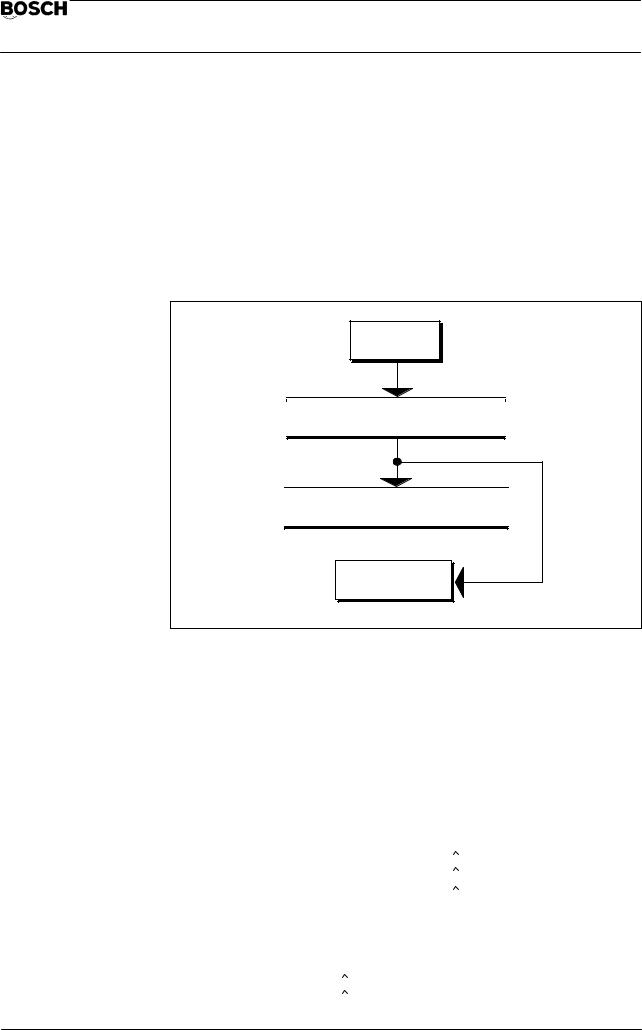
Start and end point selection
IDENTIFY CONTOUR
OTHER |
|
CONTOUR |
|
STORE |
CONTOUR |
|
SECTION |
|
|
|
|
|
||
|
|
|
|
|
CONTOUR |
|
|
|
|
SECTION |
|
|
|
|
|
|
|
||
SELECT START POINT (END POINT) |
|
|
||
|
|
|
|
|
ADVANCE |
BACKUP |
POSITION |
|
STORE |
INPUT |
|
|||
|
|
|
|
|
The procedure is essentially the same for both start and end point selection.
START POINT/END POINT SELECTION
Procedure:
1.start point
2.end point.
Determine
3. |
STORE |
The respective position is now stored. |
Various possibilities are available under POSITION INPUT or ADVANCE/BACKUP for positioning.
Direction of movement
ADVANCE
BACKUP
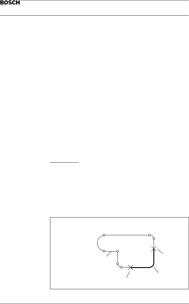
Each contour is offered here divided internally into the original contour elements in order to permit selection of the start and end points. Using the two softkeys, you can move the cursor cross over the contour to mark these points. The cursor jumps to the internal contour element transitions.
Example: Contour divided into the original contour elements
Contour with marked start/end points.
Advance/backup defines the direction of movement, whereby the original input direction is taken into account.
1 – 12

Flexible Automation
General |
CC 220 M |
|
Operating instructions |
||
|
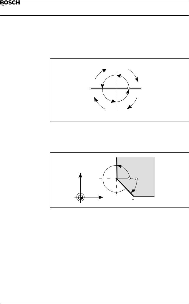
Example: Calling a contour section
When a contour section is called, the cursor cross is positioned to the start point of the first element.
Input direction |
= |
Advance |
|
 Start point
Input direction
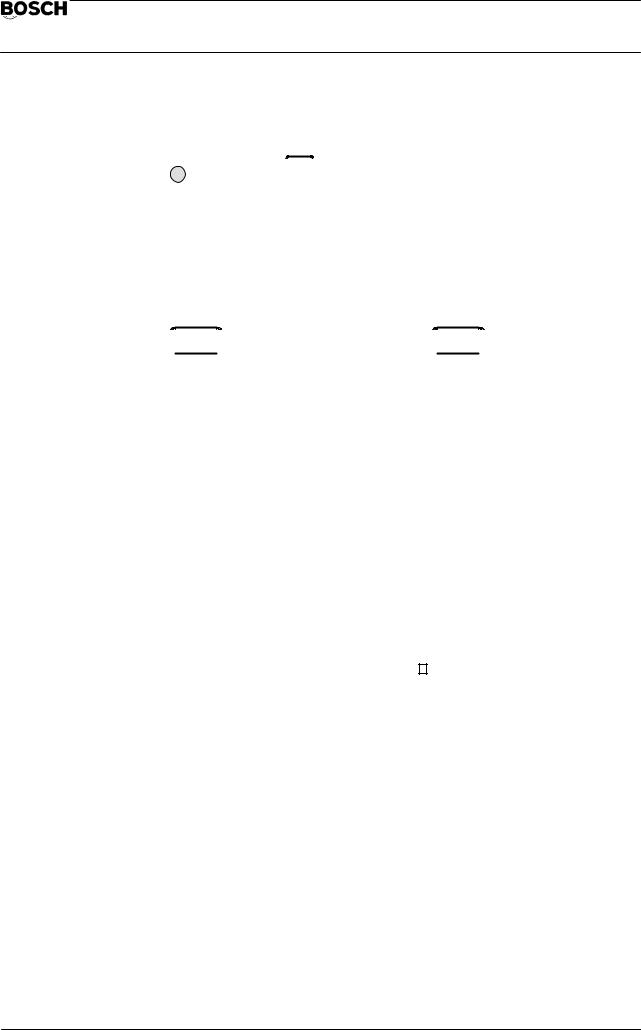
The following applies to circular and rectangular contours:
Advance |
= Movement in counter–clockwise direction |
||
|
|
|
|
Backup |
= Movement in clockwise direction |
||
Example: Circle, rectangle |
|
|
|
|
|
|
|
|
Circle |
Rectangle |
|
|
|
|
|
|
|
|
|
2 semi–circles |
4 contour elements |
|
”straight line” |
The respective position is marked by the cursor cross
1 – 13

Flexible Automation
General |
CC 220 M |
|
Operating instructions |
||
|
Position input
Any point on the offered contour can be determined here as the start or end point.
You are thus independent of the coarse selection of transition points via
ADVANCE/BACKUP.
POSITION
INPUT
This is followed by the operating level
Example: Start point selection
SELECT START POINT
|
METRIC |
ABSOLUTE |
|
|
NUMERIC |
|
INCH |
INCREMENT |
|
|
GRAPHIC |
The current display appears with the selected contour. A cross–hair extending over the whole display marks the suggested start point. The input window POSITION INPUT is displayed.
Example: Position input
|
|
|
|
|
|
|
|
POSITION INPUT |
|
|
|
|
|
|
|
|
|
|
|
COORDINATE X |
= |
|
0.000 |
|
|
COORDINATE Y |
= |
|
–10.000 |
|
|
... DISTANCE |
= |
|
|
|
|
... ANGLE |
= |
|
|
|
|
POSITIONING MODE |
= |
|
FINE |
|
|
|
|
|
|
|
|
|
|
|
|
SELECT START POINT
|
METRIC |
ABSOLUTE |
|
|
NUMERIC |
|
INCH |
INCREMENT |
|
|
GRAPHIC |
The displayed window shows the current position in numerical form.
The cursor cross is set by entering the coordinate position. This input can be made either numerically or graphically (see ”Numeric/graphic position input”, Page 1–16).
Example: Input window, position input
|
|
|
|
|
|
|
POSITION INPUT |
|
|
|
|
|
|
|
|
|
COORDINATE X |
= |
Display of the Cartesian coordinates |
|
|
COORDINATE Y |
= |
of the currently set start point |
|
|
..... DISTANCE |
= |
Polar coordinate input |
|
|
..... ANGLE |
= |
|
|
|
POSITIONING MODE= |
COARSE/FINE selection with cursor keys |
|
|
|
|
|
|
|
|
|
|
|
1 – 14

Flexible Automation
General |
CC 220 M |
|
Operating instructions |
||
|
Explanations for position input
COORDINATE X = 40.000
COORDINATE Y = 50.000
Indication of the Cartesian coordinates of the currently set point.
All positions are displayed as Cartesian coordinates, irrespective of the input.
....DISTANCE =
....ANGLE =
You can enter the current point in polar coordinates (see ”Polar coordinates”, Page 1–8).
Mixed input of Cartesian/polar coordinates is possible. The position must be unambiguously defined by two inputs in each case.
Table: Coordinate input for unambiguous point definition
COORDINATE X
COORDINATE Y
..... DISTANCE
..... ANGLE
The message INPUT DATA INCONSISTENT appears if the position input is ambiguous.
POSITIONING MODE = FINE/COARSE
You can alternatively select COARSE or FINE (default setting) with the cursor keys
or 


 .
.
COARSE: The contour point is the start position of a contour element of the current contour which is closest to the graphically or numerically entered point.
Example: COARSE positioning mode
Selected contour
The cross–hair position determines the start point on the contour.
Start or end point
1 – 15

Flexible Automation
General |
CC 220 M |
|
Operating instructions |
||
|
FINE: |
The contour point is the position of a contour element of the current |
|
contour which is nearest to the graphically or numerically entered |
|
point. |
Example: FINE positioning mode
Selected contour
The cross–hair position determines the start point on the contour.
Start or end point
Numeric/graphic position input
You determine the input mode by means of the toggle softkey. The currently active status is shown inverted.
NUMERIC |
|
GRAPHIC |
Default setting NUMERIC. |
|
Numeric input
You define the unambiguous position (Cartesian/polar). The cross–hair marks the input position. The contour is marked in accordance with the positioning mode (coarse/fine) after the point is accepted.
Unit of measurement
METRIC |
|
INCH |
Coordinates can be entered in mm or inch, depending on the |
|
metric/inch selection. Inputs with mixed units are possible. The current status is shown inverted.
Measurement mode
ABSOLUTE |
|
INCREMENT |
Coordinate inputs can be made in either absolute or incremental |
|
|
form (see ”Absolute/incremental value input”, Page 1–5ff). |
|
The current status is shown inverted.
1 – 16
Flexible Automation
General |
CC 220 M |
|
Operating instructions |
||
|
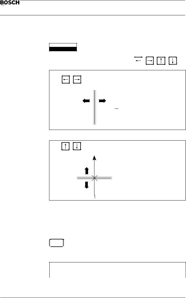
Graphic input
NUMERIC
GRAPHIC
The cross–hair is positioned with the cursor keys 

Movement on the X–axis
– X 

 + X
+ X
+ Y
Movement on the Y–axis
 – Y
– Y
Setting start and end points
After the cross–hair has been positioned, the current position is accepted with ENTER. The current positions are displayed as Cartesian coordinates in the input window.
 ENTER
ENTER You store the positions of the input window by pressing this key. The corresponding point on the contour is set and marked. This is followed by the softkey line for activation.
SELECT START POINT (END POINT)
ADVANCE |
BACKUP |
POSITION |
|
STORE |
INPUT |
|
|||
|
|
|
|
1 – 17

Flexible Automation
General |
CC 220 M |
|
Operating instructions |
||
|
Accepting the start/end point
STORE
The offered position is accepted by pressing this key. The marking cross new appears in a different color. End point selection is offered after acceptance of the start point. The contour defined with the start and end point is displayed in a different color after acceptance of the end point.
Example: Contour section acceptance
Contour with defined contour section
Contour section
Acceptance is followed by the operating level
CONTOUR SECTION
OTHER |
STORE |
|
SECTION |
||
|
||
OTHER |
|
|
SECTION |
The alternative contour section is shown. |
|
|
||
|
Contour with defined |
|
|
contour section |
|
|
”Other section” |
|
|
Other section |
Contour section acceptance
STORE
The contour section displayed in a different color is accepted by pressing this key. The user is then returned to the initial operating level.
Example: Initial operating level for contour selection GEOMETRY MACRO:
GEOMETRY MACRO
|
IDENTIFY |
ACTIVATE |
SAVE |
EDIT |
STORE |
|
|
|
|
|
|
|
|
|
|
|
|
|
|
|
1 – 18
 Loading...