


CCS 900 Ultro
CCS 900 Ultro
Discussion System
en Installation and Operating Manual


CCS 900 Ultro Table of Contents | en 3
Bosch Security Systems B.V. Installation and Operating Manual IOM_CCS900 | V1.0 | 2010.06
Table of Contents
1 About this manual 5
2 Introduction 6
3 Control Unit (CU) 7
4 Delegate and Chairman Unit 9
5 Installation 10
5.1 Connecting the Delegate and Chairman Units 10
5.2 Connecting up to 150 units 10
5.3 Locking the extension cable 11
5.4 Connecting an external microphone 11
5.5 Connecting a wireless microphone 12
5.6 Recording/playback the conversation 12
5.7 Connecting a PA-system or other external equipment 13
5.8 Connecting a telephone coupler 13
5.9 Connecting an equalizer 14
5.10 Mains connection 14
5.11 Connecting a USB cable 15
6Operation 16
6.1 Testing the connection of the Delegate and Chairman Units 16
6.2 Using the microphone button of the Delegate Unit 16
6.3 Possible-To-Speak 17
6.4 Using the microphone button of the Chairman Unit 17
6.5 Using the priority button 18
6.6 Priority mode settings in Chairman Unit 18
6.7 Open mode 19
6.8 Open mode with auto switch-off 19
6.9 Override mode 20
6.10 Chairman only mode 20
6.11 Volume control of the Delegate and Chairman Units 21
6.12 Volume control of the Delegate and Chairman Units 21
6.13 Monitoring volume control 22
6.14 Using a headphone 22
7 Built-in MP3 recorder (CCS-CURD only) 23
7.1 Introduction 23
7.2 Overview 24
7.2.1 User display 24
7.2.2 Modes of operation 24
7.2.3 Start-up screen 25
7.3 Setting up the MP3 recorder 25

4 en | Table of Contents CCS 900 Ultro
IOM_CCS900 | V1.0 | 2010.06 Installation and Operating Manual Bosch Security Systems B.V.
7.3.1 Overview of set-up icons 26
7.3.2 Deleting files 27
7.3.3 Setting the date and time 28
7.3.4 Selecting the bit rate 28
7.3.5 Continuous recording 29
7.3.6 Set internal/ external recording options 29
7.4 Record 30
7.4.1 Overview of record icons 30
7.4.2 Making a recording 31
7.4.3 Exchanging SD cards during recording 31
7.5 Pre-listen and Playback 32
7.5.1 Overview of pre-listen/ playback icons 32
7.5.2 Pre-listening to and playing back files 33
8Troubleshooting 34
9 Technical data 36
9.1 System Electrical and Electro-Acoustical Characteristics 36
9.1.1 The Control Unit (CU) 36
9.1.2 Combined Units 38
9.2 Mechanical Data 38
9.2.1 Control and Power Supply Unit 38
9.2.2 Delegate/Chairman Units 38
9.3 General data 39
9.3.1 System Environmental Conditions 39
9.3.2 Equipment Range 40
10 Appendix 41
10.1 Pin Configuration 41
10.1.1 Trunk Connections (A) 41
10.1.2 External Microphone (XLR) (B) 41
10.1.3 CINCH Connector (C) 41
10.1.4 Mains Connector (D) 41
10.1.5 Headphone Jack-plug (3.5mm) (E) 41
10.1.6 Schematics of connectors LBB 3316/00 42
10.2 Mounting Instructions 43
10.3 Bracket for Flush Mounting 44

CCS 900 Ultro About this manual | en 5
Bosch Security Systems B.V. Installation and Operating Manual IOM_CCS900 | V1.0 | 2010.06
1 About this manual
This manual provides all the information required to install and operate the CCS 900 Ultro
Discussion System.
Conventions
WARNING!
Warnings draw attention to instructions that must be followed to prevent personal injury.
CAUTION!
Cautions draw attention to instructions that must be followed to prevent damage to the
equipment.
NOTICE!
Notes draw attention to special instruction tips or other useful information.

6 en | Introduction CCS 900 Ultro
IOM_CCS900 | V1.0 | 2010.06 Installation and Operating Manual Bosch Security Systems B.V.
2 Introduction
The CCS 900 Ultro Discussion System is a discussion system for use in meeting and
conference venues with a limited number of participants.
A CCS 900 Ultro Discussion System consists of:
– One Control Unit (CU).
– Maximum 50 units of which one or more Chairman Unit(s).
– Extension cables if required (5m or 10m).
– Peripheral audio and/or telecommunication equipment.
– A built-in MP3 recorder.
The CU is the heart of the discussion system which controls the microphones of the Chairman
and Delegate Units as well as providing facilities for audio inputs and outputs. It also supplies
the power for the CU itself, Chairman Unit(s) and Delegate Unit(s).
With the use of Digital Acoustic Feedback Suppression the loudspeaker volume can be
increased significantly before feedback appears. A Digital Acoustic Feedback Suppressor is
only available in CCS-CUD / CCS-CURD.
A Delegate Unit enables participants to actively join in a discussion (i.e. speaking and
listening) by means of a microphone, controlled by an on/off button and a built-in loudspeaker
or external headphone.
A Chairman Unit has the same function as a Delegate Unit with the addition of a 'Priority'
button, that enables its operator to control the debate by temporary or permanently
overruling and muting all active microphones, depending on an internal setting in the
Chairman Unit.
The built-in MP3 recorder enables participants to: record discussions; listen to discussions
before playing it back to the floor; play discussions back to delegates.
CCS 900 Ultro Control Unit (CU) | en 7
Bosch Security Systems B.V. Installation and Operating Manual IOM_CCS900 | V1.0 | 2010.06
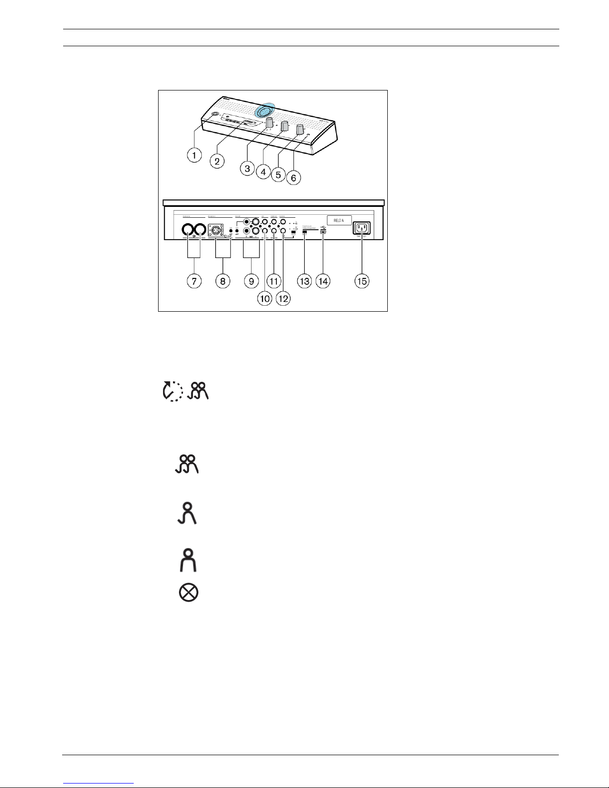
3 Control Unit (CU)
Figure 3.1 Control Unit
1. Mains On/Off switch.
2. MP3 recorder (for more information, see section 7).
3. Microphone-mode switch.
Open mode with auto switch-off. To select the maximum number of delegate
microphones to be activated simultaneously (1, 2, 3 or 4).The microphone
automatically switches off if the speaker does not speak for 30 seconds. The
microphone can manually be switched off by pushing the button on the
Delegate Unit.
Open mode. To select the maximum number of delegate microphones to be
activated simultaneously (1, 2, 3 or 4). The microphone must be switched on or
off manually by pushing the button on the Delegate Unit.
Override mode. Only one delegate microphone can be activated. If a new
delegate presses his microphone button, the microphone unit of the current
speaker will be switched off.
Chaiman only mode. Only the Chairman Units can be activated.
Test mode. For proper installation check. All the red LED’s and the light-rings
of the connected units will lit, if properly connected.
4. Speaker volume control of all connected Delegate and Chairman Units.
5. Volume control of the speaker or headphone of the CU.
6. Headphone connection with 3.5 mm stereo jack plug socket.
7. Trunk output 1 and 2. For loop through connection of the Delegate and Chairman Units.
To each output a maximum of 25 units can be connected. The maximum length of cable
between the outputs of the CU and the last unit in the system is 100 m (328 ft.).
8. Microphone input with gain adjustment for external microphone. The external
microphone will be muted when the priority button on the Chairman Unit is pressed.
9. Recorder input with gain control and recorder output connection.

8 en | Control Unit (CU) CCS 900 Ultro
IOM_CCS900 | V1.0 | 2010.06 Installation and Operating Manual Bosch Security Systems B.V.
10. Line input and output for connecting a PA-system or other audio equipment.
11. Telephone coupler input and output for connecting a remote participant.
12. Insertion connection. To connect an external audio equalizer for speech quality
improvement under difficult acoustic conditions (1 = without equalizer, 0 = insertion
connection is internally open, providing means to connect an external equalizer in the
path from microphone signals to delegate/chairman loudspeakers).
13. Digital Acoustic Feedback Suppressor (DAFS) switch to activate or deactivate the DAFS
(optional).
14. USB connector. Used for downloading recorded speech to a PC (optional).
15. Mains input connection. Use the included mains cord to connect the CU to the mains
socket. In some countries it may be necessary to replace the supplied mains cable by a
local one. Brown = live, blue = neutral and green/yellow = earth. (Replacement and color
indication not applicable to mains cords for North America).
NOTICE!
The telephone input signal to the CU is not added to the telephone output signal from the CU
to prevent line echo due to feedback.
NOTICE!
Position "1" required for internal loop-through of the microphone signals to the Delegate /
Chairman Unit loudspeakers.
CCS 900 Ultro Delegate and Chairman Unit | en 9
Bosch Security Systems B.V. Installation and Operating Manual IOM_CCS900 | V1.0 | 2010.06
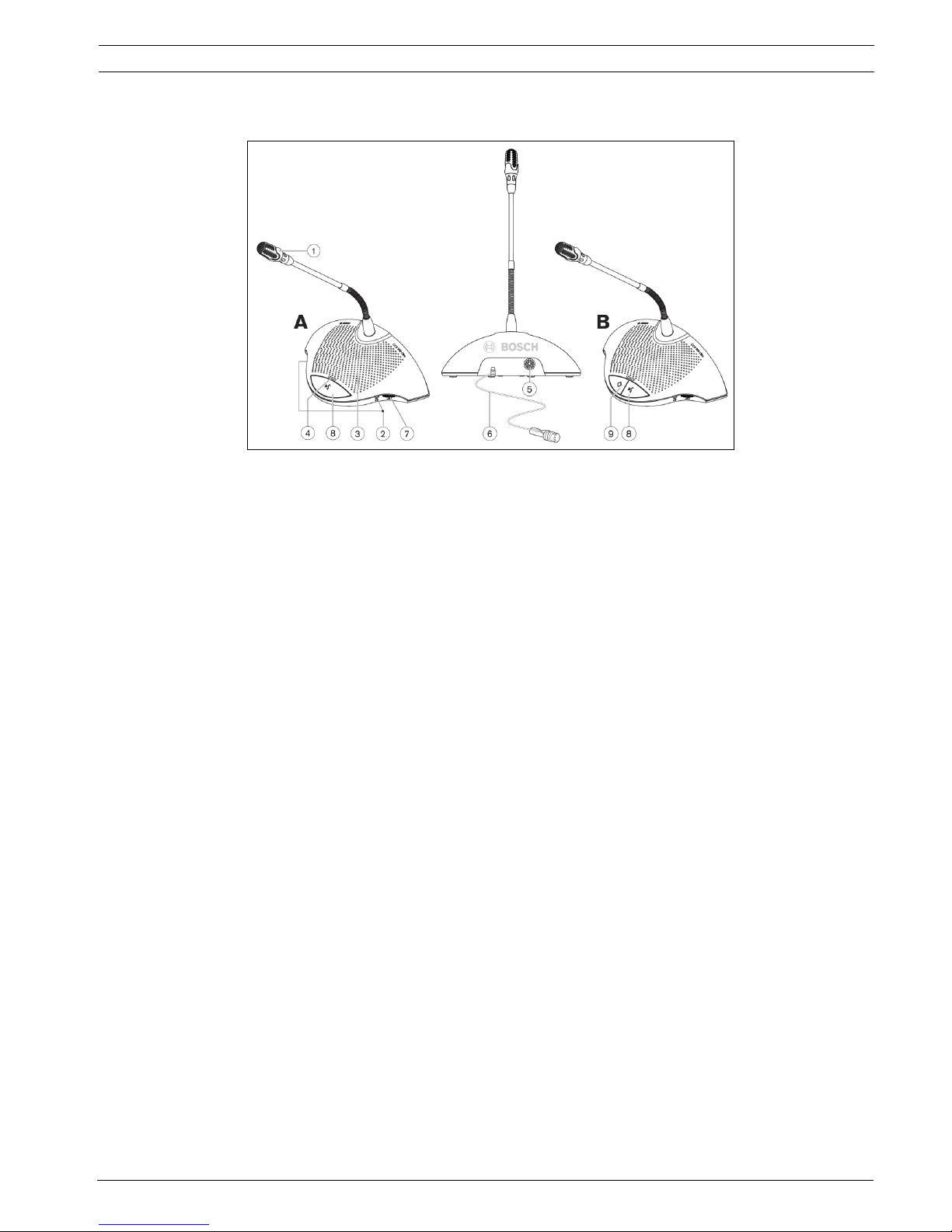
4 Delegate and Chairman Unit
Figure 4.1
The Chairman Unit (B) has the same function as a Delegate Unit (A) with the exception of a
'priority' button and the Possible-To-Speak indication.
1. Microphone with red illuminated indicator ring, lights when the microphone is ON.
2. Two 3.5 mm stereo headphone sockets, one at each side, for headphone or recorder
connection. Insertion of a headphone jack in one or both sockets automatically mutes the
unit's loudspeaker.
3. Built-in loudspeaker, automatically muted when the microphone is on.
4. Bi-color LED indicator above the microphone push button. Red for microphone on, white
for Possible-To-Speak indication (Delegate Unit only).
5. 7-pole circular female socket for loop through connection to the next unit.
6. 2m flying lead connection cable with sturdy moulded 7-pole circular male connector for
connection to the previous unit or CU.
7. Rotary volume control for headphones only.
8. Microphone ON/OFF push-button.
9. Chairman Priority button. When pressed emits chime tone, overrules/mutes all active
microphones of Delegate Units in the system and keeps the chairman's microphone on
for as long as the button is pressed (setting can be changed in the Chairman Unit).
In systems with several Chairman Units these settings are independently selectable for
each Chairman Unit.
10 en | Installation CCS 900 Ultro
IOM_CCS900 | V1.0 | 2010.06 Installation and Operating Manual Bosch Security Systems B.V.
5 Installation
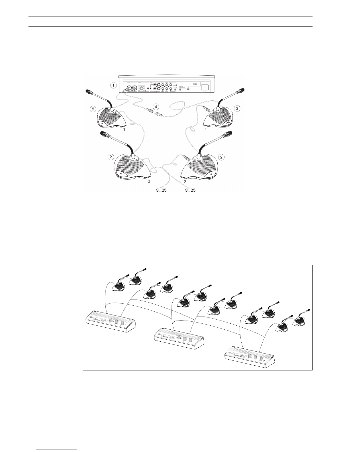
5.1 Connecting the Delegate and Chairman Units
Figure 5.1
Connect the Delegate (2) and Chairman (3) Units to the trunk connectors of the CU (1). Use
an extension cable (4) if necessary.
5.2 Connecting up to 150 units
The CCS 900 Ultro can be used with up to 150 units by adding a maximum of 2 additional
Control Units acting as power supply units only. Please contact your local Bosch
representative for the installation instructions.
Figure 5.2 Connecting 6 x 25 units
CCS 900 Ultro Installation | en 11
Bosch Security Systems B.V. Installation and Operating Manual IOM_CCS900 | V1.0 | 2010.06
5.3 Locking the extension cable
Figure 5.3
Cable locking clamps can be used in combination with the extension cables to prevent
accidental disconnection.
5.4 Connecting an external microphone
Figure 5.4
Put the external microphone (2) connector in the microphone input of the CU (1). Adjust the
sensitivity by use of the gain control (3). Use only microphones with balanced output. The
microphone input provides a 12V phantom power supply.
12 en | Installation CCS 900 Ultro
IOM_CCS900 | V1.0 | 2010.06 Installation and Operating Manual Bosch Security Systems B.V.
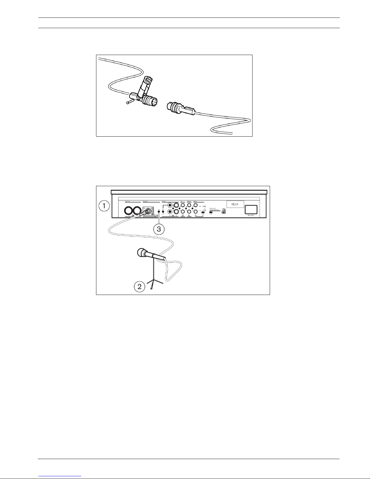
5.5 Connecting a wireless microphone
Figure 5.5
Connecting a wireless microphone to the external microphone input is possible with the
included 50dB attenuator. This way of connection allows interruption of the wireless
microphone by the chairman's priority button.
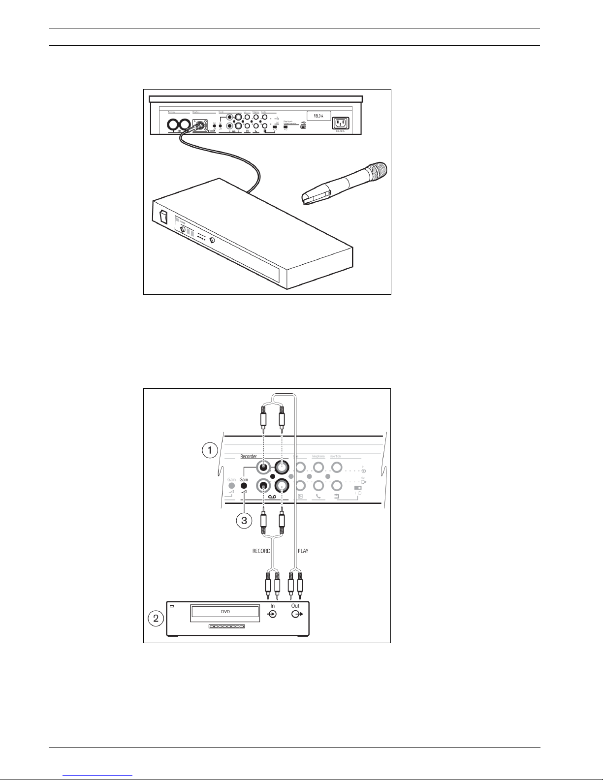
5.6 Recording/playback the conversation
Figure 5.6
Connect the cabling of the recorder device (2) to the recorder input and output of the CU (1).
Use the gain control (3) to adjust the sensitivity of the recorder input of the CU.
CCS 900 Ultro Installation | en 13
Bosch Security Systems B.V. Installation and Operating Manual IOM_CCS900 | V1.0 | 2010.06
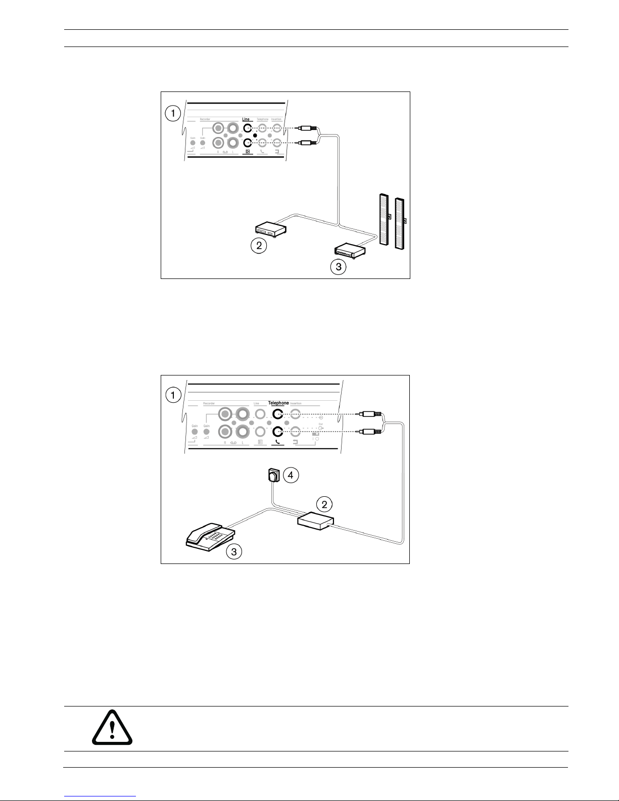
5.7 Connecting a PA-system or other external equipment
Figure 5.7
Connect a PA-system (3) or other devices (2) to the in- and output of the CU (1). Connect
audio sources to the line input, a PA amplifier or other sound-processing devices to the line
output.
5.8 Connecting a telephone coupler
Figure 5.8
Connect the telephone coupler (2) to the telephone input and output of the CU (1). The
telephone coupler is further connected to the telephone wall socket (4) and a telephone (3)
for dialing.
A connection to a telephone network must always be made via a telephone coupler that
provides adequate isolation between the telephone network (PBX) and the CCS 900 Ultro
system. The telephone coupler shall also meet all relevant requirements for this type of
communication equipment as imposed by law and/or responsible telecommunication
organizations in the country of use.
CAUTION!
Never try to make a direct connection between the telephone network and the CCS 900 Ultro
discussion system.
14 en | Installation CCS 900 Ultro
IOM_CCS900 | V1.0 | 2010.06 Installation and Operating Manual Bosch Security Systems B.V.
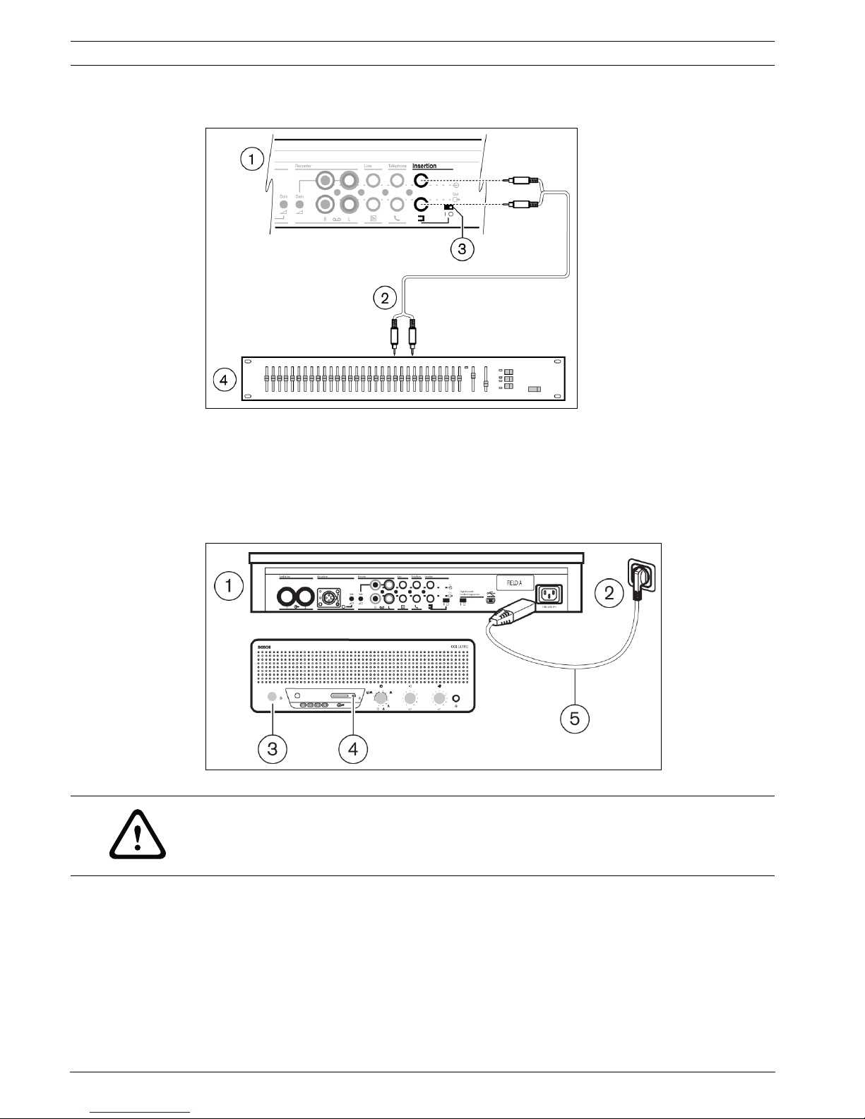
5.9 Connecting an equalizer
Figure 5.9
Put the insertion switch (3) in position "0" and connect the cabling (2) of the (mono)
equalizer (4) to the insertion input and output of the CU (1). Switch (3) must be in position
"1" (loop through) if the insertion input/output is not used.
5.10 Mains connection
Figure 5.10
Use the supplied mains cord set (5) to connect the CU (1) to a protective earthed mains
socket (2). Press the on/off switch (3) to power up the system, the display (4) will be lit
(CCS-CURD only).
WARNING!
The CU must be earthed via the mains supply for safety reasons and to ensure the specified
audio performance of the system. Do not open the CU and/or Delegate/Chairman Units, no
user serviceable parts inside.
 Loading...