


Typ1 osa / CC 220
Programming Instructions DIN
Version 102

Typ1 osa / CC 220
Programming Instructions
DIN
1070 073 661-102 (93.05) GB
(Z25 NJ)
E 1993
by Robert Bosch GmbH,
All rights reserved, including applications for protective rights. Reproduction or handing over to third parties are subject to our written permission.
Discretionary charge 30.– DM

Flexible Automation
CC 220/320 M
Contents
Programming Instructions
Contents
Safety instructions
Preliminary remark
. . . . . . . . . . . . . . . . . . . . . . . . . . . . . . . . . . . . . . . . . . . . . . . . . . . . . . . . . . Safety − 1
. . . . . . . . . . . . . . . . . . . . . . . . . . . . . . . . . . . . . . . . . . . . . . . . . . . . . . . . . Prelim. − 1
Abbreviations used . . . . . . . . . . . . . . . . . . . . . . . . . . . . . . . . . . . . . . . . . . . . . . . . . . . . . . . . . . . . |
0 − 1 |
1General
General notes . . . . . . . . . . . . . . . . . . . . . . . . . . . . . . . . . . . . . . . . . . . . . . . . . . . . . . . . . . . . . . . . . . . . . . . 1 − 1 Definitions . . . . . . . . . . . . . . . . . . . . . . . . . . . . . . . . . . . . . . . . . . . . . . . . . . . . . . . . . . . . . . . . . . . . . . . . . . 1 − 2 Program structure . . . . . . . . . . . . . . . . . . . . . . . . . . . . . . . . . . . . . . . . . . . . . . . . . . . . . . . . . . . . . . . . . . . 1 − 6 Characters used . . . . . . . . . . . . . . . . . . . . . . . . . . . . . . . . . . . . . . . . . . . . . . . . . . . . . . . . . . . . . . . . . . . . 1 − 10 Files . . . . . . . . . . . . . . . . . . . . . . . . . . . . . . . . . . . . . . . . . . . . . . . . . . . . . . . . . . . . . . . . . . . . . . . . . . . . . . 1 − 11 Operation . . . . . . . . . . . . . . . . . . . . . . . . . . . . . . . . . . . . . . . . . . . . . . . . . . . . . . . . . . . . . . . . . . . . . . . . . 1 − 13 Leader programming . . . . . . . . . . . . . . . . . . . . . . . . . . . . . . . . . . . . . . . . . . . . . . . . . . . . . . . . . . . . . . . 1 − 14 Prompt programming . . . . . . . . . . . . . . . . . . . . . . . . . . . . . . . . . . . . . . . . . . . . . . . . . . . . . . . . . . . . . . . 1 − 15 Standard programming formats . . . . . . . . . . . . . . . . . . . . . . . . . . . . . . . . . . . . . . . . . . . . . . . . . . . . . . 1 − 17
2G functions
G Codes |
. . . . . . . . . . . . . . . . . . . . . . . . . . . . . . . . . . . . . . . . . . . . . . . . . . . . . . . . . . . . . . . . . |
. 2 − 1 |
G0 |
Linear interpolation with rapid traverse . . . . . . . . . . . . . . . . . . . . . . . . . . . . . . . |
. 2 − 5 |
G1 |
Linear interpolation with feedrate . . . . . . . . . . . . . . . . . . . . . . . . . . . . . . . . . . . . |
. 2 − 6 |
G2/G3 |
Circular interpolation . . . . . . . . . . . . . . . . . . . . . . . . . . . . . . . . . . . . . . . . . . . . . . . |
. 2 − 7 |
|
Helical motion . . . . . . . . . . . . . . . . . . . . . . . . . . . . . . . . . . . . . . . . . . . . . . . . . . . . . |
2 − 11 |
|
Cylinder surface milling . . . . . . . . . . . . . . . . . . . . . . . . . . . . . . . . . . . . . . . . . . . |
2 − 12 |
G4, G104 |
Dwell time . . . . . . . . . . . . . . . . . . . . . . . . . . . . . . . . . . . . . . . . . . . . . . . . . . . . . . . . |
2 − 14 |
G5 |
Circular interpolation with tangential entry . . . . . . . . . . . . . . . . . . . . . . . . . . . . |
2 − 15 |
G6, G7 |
Acceleration programming ON/OFF . . . . . . . . . . . . . . . . . . . . . . . . . . . . . . . . . |
2 − 16 |
G8, G9 |
Path slope ON/OFF . . . . . . . . . . . . . . . . . . . . . . . . . . . . . . . . . . . . . . . . . . . . . . . . |
2 − 17 |
G10 − G13 |
Polar coordinate programming . . . . . . . . . . . . . . . . . . . . . . . . . . . . . . . . . . . . . . |
2 − 18 |
G14, G15 |
KV programming ON/OFF . . . . . . . . . . . . . . . . . . . . . . . . . . . . . . . . . . . . . . . . . . |
2 − 29 |
G16 |
KV measurement (lag measurement) . . . . . . . . . . . . . . . . . . . . . . . . . . . . . . . . |
2 − 30 |
G17 − G19 |
Plane selection X/Y, Z/X, Y/Z plane . . . . . . . . . . . . . . . . . . . . . . . . . . . . . . . . . . . |
2 − 31 |
G20 |
Plane selection of 2 out of 6 axes . . . . . . . . . . . . . . . . . . . . . . . . . . . . . . . . . . . . |
2 − 32 |
G22 |
Subroutine call P, K, V level . . . . . . . . . . . . . . . . . . . . . . . . . . . . . . . . . . . . . . . . . |
2 − 33 |
without G22 |
Subroutine call via P/Q address . . . . . . . . . . . . . . . . . . . . . . . . . . . . . . . . . . . . . |
2 − 34 |
G23 |
Conditional jump . . . . . . . . . . . . . . . . . . . . . . . . . . . . . . . . . . . . . . . . . . . . . . . . . . |
2 − 35 |
G24 |
Unconditional jump . . . . . . . . . . . . . . . . . . . . . . . . . . . . . . . . . . . . . . . . . . . . . . . . |
2 − 36 |
G25, G26 |
Permitted working area − minimum values/maximum values . . . . . . . . . . . . |
2 − 37 |
G125, G126 |
Forbidden working area − minimum values/maximum values . . . . . . . . . . . |
2 − 37 |
G27 |
Cancellation of the working area limitation . . . . . . . . . . . . . . . . . . . . . . . . . . . . |
2 − 37 |
G28, G128, G29 Corner deceleration ON . . . . . . . . . . . . . . . . . . . . . . . . . . . . . . . . . . . . . . . . . . . |
2 − 41 |
|
|
Corner deceleration/acceleration OFF . . . . . . . . . . . . . . . . . . . . . . . . . . . . . . . . |
2 − 42 |
G33 |
Thread cutting . . . . . . . . . . . . . . . . . . . . . . . . . . . . . . . . . . . . . . . . . . . . . . . . . . . . |
2 − 43 |
G37 − G39 |
Programmable mirror image . . . . . . . . . . . . . . . . . . . . . . . . . . . . . . . . . . . . . . . . |
2 − 55 |
G37 − G39 |
Coordinate rotation . . . . . . . . . . . . . . . . . . . . . . . . . . . . . . . . . . . . . . . . . . . . . . . . |
2 − 60 |
G38 − G39 |
Scaling . . . . . . . . . . . . . . . . . . . . . . . . . . . . . . . . . . . . . . . . . . . . . . . . . . . . . . . . . . . |
2 − 65 |
Cont. − 1

Flexible Automation
CC 220/320 M
Contents
Programming Instructions
|
G40, G41, G42 Cutter path compensation . . . . . . . . . . . . . . . . . . . . . . . . . . . . . . . . . . . . . . . . . |
. 2 − 70 |
|
|
G140, ()43, ()44 Paraxial compensation . . . . . . . . . . . . . . . . . . . . . . . . . . . . . . . . . . . . . . . . . . . . |
. 2 − 71 |
|
|
G43, G44 |
Spatial tool offset . . . . . . . . . . . . . . . . . . . . . . . . . . . . . . . . . . . . . . . . . . . . . . . . . |
. 2 − 74 |
|
G53 |
Zero offsets (ZO) OFF . . . . . . . . . . . . . . . . . . . . . . . . . . . . . . . . . . . . . . . . . . . . . |
. 2 − 78 |
|
G()54−G()59 |
Zero offsets (ZO) ON . . . . . . . . . . . . . . . . . . . . . . . . . . . . . . . . . . . . . . . . . . . . . . |
. 2 − 78 |
|
G60, G67 |
Programmed zero offset (ZO) ON/OFF . . . . . . . . . . . . . . . . . . . . . . . . . . . . . . |
. 2 − 80 |
|
G160, G167 |
External zero offset (ZO) ON/OFF . . . . . . . . . . . . . . . . . . . . . . . . . . . . . . . . . . |
. 2 − 81 |
|
G61, G62 |
In position programming ON/OFF . . . . . . . . . . . . . . . . . . . . . . . . . . . . . . . . . . |
. 2 − 83 |
|
G63, G66 |
Set 100 % feedrate . . . . . . . . . . . . . . . . . . . . . . . . . . . . . . . . . . . . . . . . . . . . . . . |
. 2 − 84 |
|
G64, G65 |
Feedrate override . . . . . . . . . . . . . . . . . . . . . . . . . . . . . . . . . . . . . . . . . . . . . . . . . |
. 2 − 85 |
|
G68, G69 |
Contour transitions . . . . . . . . . . . . . . . . . . . . . . . . . . . . . . . . . . . . . . . . . . . . . . . |
. 2 − 87 |
|
G70 |
Inch programming . . . . . . . . . . . . . . . . . . . . . . . . . . . . . . . . . . . . . . . . . . . . . . . . |
. 2 − 88 |
|
G71 |
Metric programming . . . . . . . . . . . . . . . . . . . . . . . . . . . . . . . . . . . . . . . . . . . . . . |
. 2 − 88 |
|
G73 |
Linear interpolation with IN POSITION PROGRAMMING . . . . . . . . . . . . . . . |
. 2 − 89 |
|
G74 |
Traversing to reference point . . . . . . . . . . . . . . . . . . . . . . . . . . . . . . . . . . . . . . . |
. 2 − 90 |
|
G174 |
Traversing to reference point via intermediate position . . . . . . . . . . . . . . . . . . |
2 − 91 |
|
G274 |
Withdrawal from reference point via intermediate position . . . . . . . . . . . . . . |
2 − 91 |
|
G75 |
Measuring probe input . . . . . . . . . . . . . . . . . . . . . . . . . . . . . . . . . . . . . . . . . . . . . |
2 − 93 |
|
G76 |
Traverse to fixed machine axis position . . . . . . . . . . . . . . . . . . . . . . . . . . . . . . |
2 − 94 |
|
G78, G79 |
Drilling axis switchover . . . . . . . . . . . . . . . . . . . . . . . . . . . . . . . . . . . . . . . . . . . . . |
2 − 96 |
|
G80 − G86 |
Drilling cycles . . . . . . . . . . . . . . . . . . . . . . . . . . . . . . . . . . . . . . . . . . . . . . . . . . . . . |
2 − 99 |
|
G81 |
Drilling 1 . . . . . . . . . . . . . . . . . . . . . . . . . . . . . . . . . . . . . . . . . . . . . . . . . . . . . . . . |
2 − 103 |
|
G82 |
Drilling 2 . . . . . . . . . . . . . . . . . . . . . . . . . . . . . . . . . . . . . . . . . . . . . . . . . . . . . . . . |
2 − 103 |
|
G83 |
Deep hole drilling . . . . . . . . . . . . . . . . . . . . . . . . . . . . . . . . . . . . . . . . . . . . . . . . . |
2 − 104 |
|
G84 |
Tapping . . . . . . . . . . . . . . . . . . . . . . . . . . . . . . . . . . . . . . . . . . . . . . . . . . . . . . . . . |
2 − 105 |
|
G85 |
Boring out 1 . . . . . . . . . . . . . . . . . . . . . . . . . . . . . . . . . . . . . . . . . . . . . . . . . . . . . |
2 − 106 |
|
G86 |
Boring out 2 . . . . . . . . . . . . . . . . . . . . . . . . . . . . . . . . . . . . . . . . . . . . . . . . . . . . . |
2 − 106 |
|
G90 |
Dimensioning system − absolute . . . . . . . . . . . . . . . . . . . . . . . . . . . . . . . . . . |
2 − 110 |
|
G91 |
Dimensioning system − incremental . . . . . . . . . . . . . . . . . . . . . . . . . . . . . . . . |
2 − 110 |
|
G92 |
Set actual value . . . . . . . . . . . . . . . . . . . . . . . . . . . . . . . . . . . . . . . . . . . . . . . . . . |
2 − 111 |
|
G192, G292 |
Spindle speed limitation . . . . . . . . . . . . . . . . . . . . . . . . . . . . . . . . . . . . . . . . . . . |
2 − 112 |
|
G892, G992 |
Laser power control . . . . . . . . . . . . . . . . . . . . . . . . . . . . . . . . . . . . . . . . . . . . . . . |
2 − 113 |
|
G93 |
Time programming . . . . . . . . . . . . . . . . . . . . . . . . . . . . . . . . . . . . . . . . . . . . . . . |
2 − 115 |
|
G94 |
Feedrate mm/min . . . . . . . . . . . . . . . . . . . . . . . . . . . . . . . . . . . . . . . . . . . . . . . . |
2 − 116 |
|
G95 |
Feedrate mm/rev . . . . . . . . . . . . . . . . . . . . . . . . . . . . . . . . . . . . . . . . . . . . . . . . . |
2 − 117 |
|
G98 |
Fast retract ON . . . . . . . . . . . . . . . . . . . . . . . . . . . . . . . . . . . . . . . . . . . . . . . . . . . |
2 − 118 |
|
G99 |
Fast retract OFF . . . . . . . . . . . . . . . . . . . . . . . . . . . . . . . . . . . . . . . . . . . . . . . . . . |
2 − 118 |
|
G130/G131/G132 |
Tangential tool guidance . . . . . . . . . . . . . . . . . . . . . . . . . . . . . . . . . . . . . . . . . . |
2 − 119 |
|
G()45/G146 |
External tool compensation . . . . . . . . . . . . . . . . . . . . . . . . . . . . . . . . . . . . . . . . |
2 − 122 |
|
G993/G994 |
Asynchronous reciprocating axis . . . . . . . . . . . . . . . . . . . . . . . . . . . . . . . . . . . |
2 − 125 |
|
G32 |
Exact tapping . . . . . . . . . . . . . . . . . . . . . . . . . . . . . . . . . . . . . . . . . . . . . . . . . . . . |
2 − 127 |
|
G101, G102 |
Spline interpolation . . . . . . . . . . . . . . . . . . . . . . . . . . . . . . . . . . . . . . . . . . . . . . . |
2 − 129 |
|
G114, G115 |
Feed forward control . . . . . . . . . . . . . . . . . . . . . . . . . . . . . . . . . . . . . . . . . . . . . . |
2 − 132 |
|
G8, G108, G109, |
|
|
|
G110 |
Contour−dependent feedrate override . . . . . . . . . . . . . . . . . . . . . . . . . . . . . . |
2 − 134 |
|
G51, G52 |
Workpiece zero shift . . . . . . . . . . . . . . . . . . . . . . . . . . . . . . . . . . . . . . . . . . . . . . |
2 − 145 |
|
G995 |
Linking of axes |
2 − 147 |
|
|||
|
|
|
|
Cont. − 2

Flexible Automation
CC 220/320 M
Contents
Programming Instructions
3Auxiliary and supplementary functions
Address F |
Feedrate . . . . . . . . . . . . . . . . . . . . . . . . . . . . . . . . . . . . . . . . . . . . . . . . . . . . . . . . . . |
3 − 1 |
Address S |
Spindle speed . . . . . . . . . . . . . . . . . . . . . . . . . . . . . . . . . . . . . . . . . . . . . . . . . . . . . |
3 − 2 |
Address M |
M−codes . . . . . . . . . . . . . . . . . . . . . . . . . . . . . . . . . . . . . . . . . . . . . . . . . . . . . . . . . |
3 − 4 |
|
Programmable spindle orientation (M19) . . . . . . . . . . . . . . . . . . . . . . . . . . . . . . |
3 − 5 |
Address T |
Tool selection . . . . . . . . . . . . . . . . . . . . . . . . . . . . . . . . . . . . . . . . . . . . . . . . . . . . . . |
3 − 8 |
4Tool compensation
Length compensation . . . . . . . . . . . . . . . . . . . . . . . . . . . . . . . . . . . . . . . . . . . . . . . . . . . . . . . . . . . . . . . . 4 − 2 Compensation sign for length compensation . . . . . . . . . . . . . . . . . . . . . . . . . . . . . . . . . . . . . . . . . . . . 4 − 3 Radius compensation . . . . . . . . . . . . . . . . . . . . . . . . . . . . . . . . . . . . . . . . . . . . . . . . . . . . . . . . . . . . . . . . 4 − 4 Tool table . . . . . . . . . . . . . . . . . . . . . . . . . . . . . . . . . . . . . . . . . . . . . . . . . . . . . . . . . . . . . . . . . . . . . . . . . . . 4 − 5 Start point, start of contour . . . . . . . . . . . . . . . . . . . . . . . . . . . . . . . . . . . . . . . . . . . . . . . . . . . . . . . . . . . . 4 − 7 Contour entry with various start points . . . . . . . . . . . . . . . . . . . . . . . . . . . . . . . . . . . . . . . . . . . . . . . . . . 4 − 8 Contour transitions with G68 . . . . . . . . . . . . . . . . . . . . . . . . . . . . . . . . . . . . . . . . . . . . . . . . . . . . . . . . . . 4 − 9 Contour transitions with G69 . . . . . . . . . . . . . . . . . . . . . . . . . . . . . . . . . . . . . . . . . . . . . . . . . . . . . . . . . 4 − 10 Examples . . . . . . . . . . . . . . . . . . . . . . . . . . . . . . . . . . . . . . . . . . . . . . . . . . . . . . . . . . . . . . . . . . . . . . . . . 4 − 11 End point, deactivation of compensation . . . . . . . . . . . . . . . . . . . . . . . . . . . . . . . . . . . . . . . . . . . . . . 4 − 12 Outside corners . . . . . . . . . . . . . . . . . . . . . . . . . . . . . . . . . . . . . . . . . . . . . . . . . . . . . . . . . . . . . . . . . . . . 4 − 14
5 |
Special functions |
|
|
Rotary axis programming (ROTARY/ENDLESS axis type) . . . . . . . . . . . . . . . . . . . . . . . . . . . . . . . . |
. 5 − 1 |
|
Positioning axes (Hirth axes) . . . . . . . . . . . . . . . . . . . . . . . . . . . . . . . . . . . . . . . . . . . . . . . . . . . . . . . . . |
. 5 − 4 |
|
Read monitoring (E code) . . . . . . . . . . . . . . . . . . . . . . . . . . . . . . . . . . . . . . . . . . . . . . . . . . . . . . . . . . . |
. 5 − 5 |
|
Quadrant programming . . . . . . . . . . . . . . . . . . . . . . . . . . . . . . . . . . . . . . . . . . . . . . . . . . . . . . . . . . . . . |
. 5 − 8 |
|
Direction−dependent feedrate override . . . . . . . . . . . . . . . . . . . . . . . . . . . . . . . . . . . . . . . . . . . . . . . |
5 − 10 |
6 |
Annex |
|
|
Machine error and status display (MZA) . . . . . . . . . . . . . . . . . . . . . . . . . . . . . . . . . . . . . . . . . . . . . . . |
. 6 − 1 |
|
Structure of an MZA file . . . . . . . . . . . . . . . . . . . . . . . . . . . . . . . . . . . . . . . . . . . . . . . . . . . . . . . . . . . . . |
. 6 − 2 |
|
Example of a part program (P file group) . . . . . . . . . . . . . . . . . . . . . . . . . . . . . . . . . . . . . . . . . . . . . . |
. 6 − 4 |
|
Example of a zero offset table (V file group) . . . . . . . . . . . . . . . . . . . . . . . . . . . . . . . . . . . . . . . . . . . . |
. 6 − 5 |
|
Example of a tool compensation table (K file group) . . . . . . . . . . . . . . . . . . . . . . . . . . . . . . . . . . . . |
. 6 − 6 |
|
Structure of a tool table . . . . . . . . . . . . . . . . . . . . . . . . . . . . . . . . . . . . . . . . . . . . . . . . . . . . . . . . . . . . . . |
. 6 − 7 |
|
Printout of an entire tool table . . . . . . . . . . . . . . . . . . . . . . . . . . . . . . . . . . . . . . . . . . . . . . . . . . . . . . . . |
. 6 − 9 |
|
ZO values entered in the ZO table at the start of the part program . . . . . . . . . . . . . . . . . . . . . . . . . |
6 − 10 |
|
Leadscrew error table (L file group) . . . . . . . . . . . . . . . . . . . . . . . . . . . . . . . . . . . . . . . . . . . . . . . . . . . |
6 − 11 |
|
Tables − ASCII character set . . . . . . . . . . . . . . . . . . . . . . . . . . . . . . . . . . . . . . . . . . . . . . . . . . . . . . . . . |
6 − 12 |
|
Punched tape code (ISO) . . . . . . . . . . . . . . . . . . . . . . . . . . . . . . . . . . . . . . . . . . . . . . . . . . . . . . . . . . . . |
6 − 13 |
|
Punched tape code (EIA) . . . . . . . . . . . . . . . . . . . . . . . . . . . . . . . . . . . . . . . . . . . . . . . . . . . . . . . . . . . . |
6 − 14 |
Cont. − 3

Flexible Automation
CC 220/320 M
Contents
Programming Instructions
Cont. − 4

Flexible Automation
CC 220/320 M
Safety instructions
Programming Instructions
Safety instructions
The following labels, intended to draw your attention to certain features, may be attached to the control components:
’ Warning of hazardous electrical voltage!
’ Warning of danger from batteries!
’ Components subject to electrostatic induction!
’ Remove mains plug before opening!
’Bolt to be used for connection of protective (PE) conductor only!
’ To be used for the connection of a shielding conductor only!
Symbols used in the manual:
To draw your attention to certain matters:

 NOTE!
NOTE!
(This item will give you supplementing explanations, recommendations, informa tion and tips)
To draw your attention to certain safety−relevant matters or instructions:

 CAUTION!
(Non−observance of instructions may result in material damage! E.g. deletion of files or damage to assemblies)

 CAUTION!
(Non−observance of instructions may result in material damage or even bodily
!injury)

Flexible Automation
CC 220/320 M
Safety instructions
Programming Instructions
Flexible Automation
CC 220/320 M
Preliminary remark
Programming Instructions
Preliminary remark
The present manual refers to the "Z25 NJ" software version of the CC 220/320 M control.

 NOTE!
NOTE!
Information on the current software version of ’your’ control can be found in the DIAGNOSTIC group operating mode after pressing the DIAGNOSTIC CONTROL and SOFTWARE VERSION softkeys.
It contains − with regard to the manual title − the information required for the proper operation of the control. For reasons of clarity, however, it does not contain all details of all possible function combinations. Likewise, since the control is as a rule a part of larger installations or systems, it is not possible to cover any imaginable case of integration or operation.
If, however, you should wish to get further, more detailed informtion, or in case if special problems occur in the operation of the control which are not, or not detailed enough, covered in this manual, please address your questions to your local Bosch service department or to our customer consultation department.
The present description does only apply to DIN programming of the CNC. For CPL programming, a separate manual is available. For programming the machine−tool manufacturer cycles, please observe the corresponding description of the machine−tool manufacturer.
Programming the control allows you to influence the axis movements (e.g. positions etc.), machining technology (e.g. feed, rpm, etc.), machining sequence (e.g. tool change, compensation, help−function output, etc.), and even the interaction between CNC and drives (e.g. KV programming). All this requires general programming knowledge on the one hand (e.g. for the logic program sequence, the description of the contour, etc.), and on the other hand knowledge of the technology of CNC lathe−turning/milling (e.g. for the selection of the correct feedrate for machining a certain material).
Therefore, programming must only be performed by correspondingly trained personnel.

 CAUTION!
Programming by insufficiently or even untrained, or unexperienced, personnel
!may result in severe damage to machines, drives, tools, workpieces or even bodily injury!
Test the programs first without axis movement! The control provides for such tests
!the TEST ON softkey in the AUTOMATIC (NC) group operating mode. If this softkey is displayed in inverse video, no movements directly initiated by a part program will be performed.
BOSCH excludes any liability for subsequent damage resulting from processing
!an NC or CPL program or of an individual block, or from manual traverse of the axes! And neither will BOSCH be liable for subsequent damage which could have been avoided by appropriate PLC programming!
Please note in this context our extensive training offer. An seminar overview can be found on the inside of the manual’s cover sheet. For details, please contact our training center (Telephone: −6062/78258).
Prelim. −1
Flexible Automation
CC 220/320 M
Preliminary remark
Programming Instructions
Prelim. −2

Flexible Automation
CC 220/320 M
Abbreviations
Programming Instructions
ABBREVIATIONS USED:
MTB |
= Machine tool builder |
CNC |
= Computerized Numerical Control |
SK |
= Softkey |
GOM |
= Group operating mode |
MP |
= Machine parameter |
ASCII |
= American Standard Code for Information Interchange |
CPL |
= Customer Programming Language |
DFS |
= Define storage |
IF |
= Interface |
UP |
= Subroutine |
MZA |
= Machine error and status display |
CLM |
= Clear memory |
EIA |
= Electronic Industries Association |
ISO |
= International Standards Organization |
CS |
= Communication store |
CR |
= Carriage Return = End−of−block character (EIA) |
LF |
= Line Feed = End−of−block character (ISO) |
STX |
= Start of Text |
ETX |
= End of Text |

 NOTE!
NOTE!
1.The programming examples should be understood as symbolic only.
2.For reasons of clarity, <CR> <LF> (end−of−block character) is omitted in the program explanations. It will only appear where it is required for a better understanding.
3.Machine−typical and machine−depending programmings have to be observed (refer to machine−tool manufacturer’s instructions).
0 − 1

Flexible Automation
CC 220/320 M
Abbreviations
Programming Instructions
0 − 2

Flexible Automation
General
CC 220/320 M
Programming Instructions
General notes
1.The G functions G900 to G990 can be optionally assigned by the customer.
2.The W tables W999999001 to W999999999 are internally assigned.
3.The program numbers P999999000 to P999999999 should not be used; they are reserved for NC internal programs such as:
−Drilling cycles (P999999081 ... 086)
−Measurement cycles (P999999901 ... 937)
−Machine−error and status display (P999999999)
−CPL / dialog call−up (P999999000 ... 003)
The machine−tool builder should place M6, M60 and other programs in the range between P 899 999 000 and P 899 999 999.
4.An axis shut down via "Drive on" (IF signal) must not be programmed.
5.Programs can be tested in fast−run mode via "Program test" or "Go Block".
1 − 1
Flexible Automation
General
CC 220/320 M
Programming Instructions
Definitions
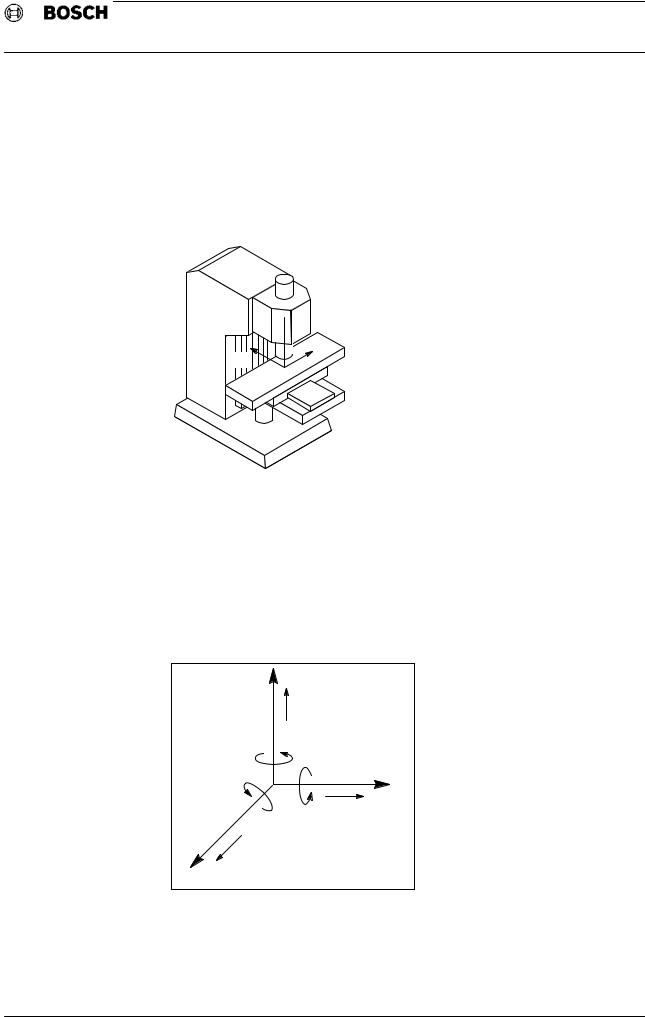
System of coordinates
The explanations contained in these instructions follow DIN 66217. This standard standardizes the direction and arrangement of the coordinate axes.
The coordinate system used is a right−handed, right−angled system with X, Y and Z axis.
 +Z
+Z
+X
+Y
Axis identification
The coordinate system is correlated in relation to the working spindle to which the Z axis runs in parallel. Positive axis direction runs from the workpiece to the tool. The X axis is parallel to the tool clamping surface and horizontal. X and Z define the location of the Y axis.
Further independently controlled axes, arranged in parallel to the main axes, are referred to as U, V, W. Rotary movements performed by machine components around the main axes (e.g. rotary axis) are referred to as A, B, C.
+Y |
|
|
|
+V |
|
|
+B |
|
|
+A |
|
+C |
+U |
+X |
|
|
|
+W |
|
|
+Z |
|
|
Axis commands
To uniform the explanation of all programmed movements, the workpiece is as sumed to be stationary, with only the tool moving (relative tool movement). All movements are referred to the assigned coordinate system.
1 − 2
Flexible Automation
General
CC 220/320 M
Programming Instructions
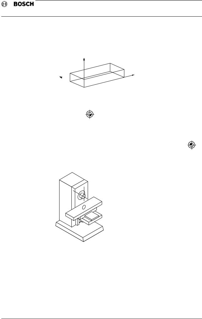
Zero points
The basis is a clockwise Cartesian coordinate system.
The Z axis is parallel to the tool, +Z extends from the tool tip into the spindle.
+Z
+Y +X
+X
The zero point of the coordinate system can be freely selected by the programmer. In the following, this point will be referred to as workpiece zero point (W) and iden
tified as follows:
W
The transformation of this coordinate system to the machine−tool coordinate sys tem by the program is performed using G92 (set actual value) or G154−G159, G254−G259 (zero offset). In the following, the zero point of the machine coordi
nates is referred to as machine zero point (M) and identified as follows:
M
The machine zero point is defined by the machine manufacturer.
 M
M
1 − 3
Flexible Automation
General
CC 220/320 M
Programming Instructions
After power−up, the CNC requires an electric signal indicating the accurate posi tion of each axis. This signal is provided by adjustable cam switches. The indicated
position is referred to as reference point (R) and identified as follows:
R
The position of the reference point of each axis is measured exactly from the ma chine zero point, and its position is memorized in the CNC.
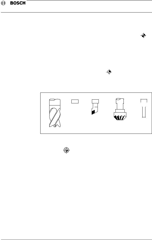
In these instructions, all axis movements are represented as a relative movement of the tool.
In this context, the diameter and length of the tool are generally not considered. The position of the tool on the programmed path corresponds to the
tool set point (N) and is identified as follows:
N
Examples
Ê
Ê
Ê É
Each program is started and ended in the program zero point (P) located outside the workpiece to ensure a safe workpiece change. The program zero point is iden
tified as follows:
P
1 − 4

Flexible Automation
General
CC 220/320 M
Programming Instructions
Fundamentals
Essentially, programming CNC controls defines the following processes:
‘Workpiece machining
‘Tool selection and change
‘Workpiece change
‘Workpiece and tool measurement.
For these definitions the CC 220/320 M features two programming options:
‘According to DIN 66025
‘CPL
Except for the drilling cycles, this manual covers programming according to DIN 66025 only. Machining is its major subject. Tool and pallet changes are machine− dependent cycles, and are not discussed here.
Part programs can be created as follows:
‘Directly on the panel of the machine via the standard arithmetic keypad or optional ASCII keyboard
‘In office−based programming stations
1 − 5
Flexible Automation
General
CC 220/320 M
Programming Instructions
Program structure
The program represents a sequence of machining steps and is divided into blocks.
These blocks contain preparatory functions, path information, auxiliary and supplementary functions. They provide information on:
‘the position
‘the technology
‘the program sequence
The number of programs is only limited by the available memory space.
Program start
During reading in, the first character of a program has to be an end−of−block character. This allows the control to recognize the start of a program. The pro gramming code (EIA/ISO) will be determined as a function of the parity of this first end−of−block character:
‘Even parity = ISO code (8 bits incl. even parity)
‘Odd parity = EIA code (8 bits incl. odd parity)
ISO and EIA code tables can be found in the annex to these instructions.

 NOTE!
NOTE!
All characters programmed before the first end−of−block character will be ig nored by the control during data in.
Program sequence
Without corresponding program instructions the program blocks will be executed one after the other. However, it is possible to influence the program sequence using the following options:
‘Subroutine calls
‘Repeat instructions
‘Jump instructions
‘"Block slash" function
End of program
The end of program is identified by
‘M30 and end−of−block character or
‘M02 and end−of−block character or
‘M2 and end−of−block character.
The effects of M02, M2 and M30 are absolutely identical.
Apart from M02, M2 or M30, no other information may be contained in the last pro gram block. M02/M2/M30 always sets power−up state except in the case of G14/G15 and G70/G71.
At the end of subroutines, M02/M2/M30 causes only a return to the calling pro gram.
1 − 6
Flexible Automation
General
CC 220/320 M
Programming Instructions
Program block
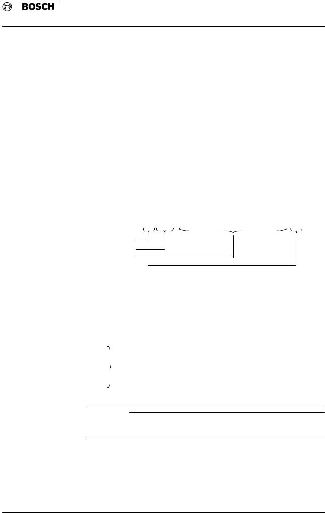
A block is made up of the block address, one or more words, and the end−of− block character.
The end−of−block character must always be written (ISO code: LF, EIA code: CR), but will not be displayed. The blocks may be of different length, but are limited to 128 characters per block. The block address forms the beginning of the block. As a principle, more than one G or M words are allowed within one block. The block address and the words may be preceded by "BLANK" and "TAB" special charac ters.However, programming "BLANKs" and "TABs" requires a lot of memory space and furthermore prolongs the block cycle time.
If a slash is programmed ahead of the block address (e.g. "/N100"), this block may be skipped during the program sequence. For this purpose the "/BLOCK SLASH" function in the "NC" group operating mode or the related interface signal must be activated (also see CC 220/320 Operating instructions, chapter 6: "Program−se quence interventions" and Interface conditions, chapter 5.1.: "Inputs of the con trol").
Example:
/ N100 G1 X255.3 Y−3240 Z20.78 F600 LF
ID
Block address
Words
End−of−block character
The block numbers should be programmed in ascending sequence. It is recom mended to avoid gaps in this sequence.
When editing the program later, up to 99 additional blocks can be inserted between two individual blocks.
Example:
N1 |
|
N1.1 |
|
. |
|
. |
may be inserted |
. |
|
N1.99 |
|
N2 |
|

 NOTE!
NOTE!
When omitting the block address the program’s readability and flexibility (jump commands) becomes worse, but the block cycle time is slightly improved.
1 − 7
Flexible Automation
General
CC 220/320 M
Programming Instructions
Program word
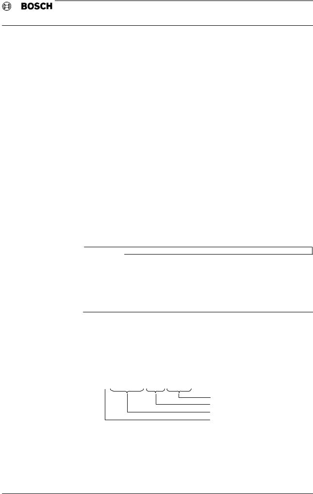
A word is made up of the address letter, the sign and a numerical string. A posi tive sign can be omitted during input. Depending on the format (integer/real), the numerical string may contain a decimal point. Within the defined limits, words of any length can be programmed. It will, however, suffice to indicate only those nu merals actually containing information.
Example
Numerical string as word contents
Numerical string without information can be omitted
R − 2 3 8 . 2 0 0
Decimal point
Sign
Address letter
Program code
Part programs programmed in EIA code (e.g. existing programs on punched tape) can be easily taken over into the CC 220/320. Output of programs (on punched tape, cassette or diskette) is only possible in ISO code.
1 − 8
Flexible Automation
General
CC 220/320 M
Programming Instructions
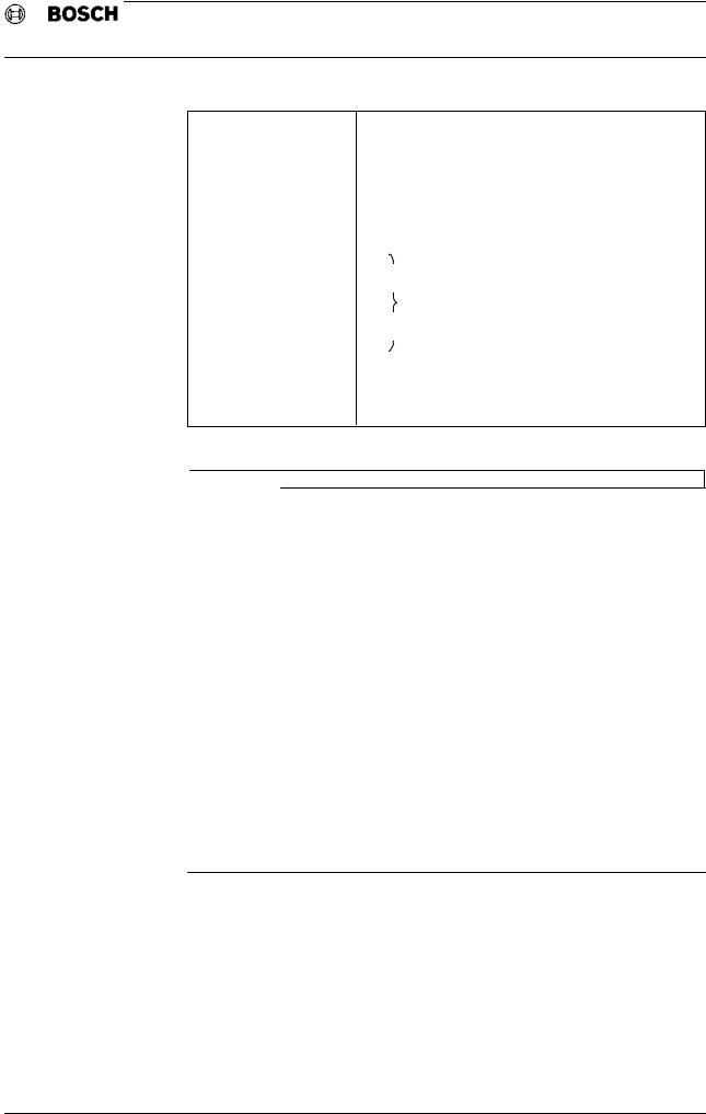
|
Character |
Meaning |
* |
NUL |
SPROCKET |
* |
STX |
START OF THE 1ST PART PROGRAM |
*CR LF
|
FILE HEADER |
DFS IDENTIFICATION |
|
CR |
|
|
LF |
|
|
−−− |
|
|
. |
|
|
. |
|
|
DATA |
NC BLOCKS |
|
. |
|
|
. |
|
|
−−− |
|
|
CR |
|
|
LF |
|
* |
ETX |
END OF PART PROGRAM |
* |
NUL |
SPROCKET |
* will be generated by the system during program output.

 NOTE!
NOTE!
‘At the program start, STX has the same meaning as Line Feed (LF) and sets the parity to ISO. All characters following STX will be evaluated (during data in). STX is output in addition to <LF> in order to facilitate the recognition of the start of useful data for connected data storage devices.
‘At the program end, ETX has the same meaning as M2 <LF> / M30 <LF> (end−of−program identification during data in). ETX is output in addition to M30 <LF> in order to facilitate the recognition of the end of useful data for connected data storage devices.
‘Ahead of each file, between the leader and the 1st LF, an STX is generated (during output).
‘When outputting programs / tables, the CNC will output M30 <LF> and ETX.
‘During output, the CNC will automatically create Carriage Return (CR) which will be ignored during data in.
‘To increase the reliability of reading in data from external media into the CNC’s program memory, the "E CODE" option (read monitoring) option is available. (see page 5−6: Read monitoring).
1 − 9

Flexible Automation
General
CC 220/320 M
Programming Instructions
Characters used
A .... Z
26 upper−case letters
0 .... |
9 |
10 numerals
− Minus sign
If the value of an input is negative, a negative sign has to be placed between the address letter and the numerical string.
+ Plus sign
Positive signs may, but do not have to be written.
End−of−block
ISO code LF, EIA code CR. The end−of−block character is an operating signal for the control and has to be located at the end of the block. The first end−of−block character read in by the control will be identified as program start.
( ) Open brackets, close brackets
Activates special logic in context with DFS and MSG (may also be used for com ment purposes).
, Comma
Special character according to MSG and DFS. Processed as a punctuation charac ter within a prompt.
. Decimal point
Used for value input.
Within text, it is merely processed as a punctuation mark.
/ Slash
If "/" is programmed ahead of a block number, the corresponding block can be skipped during program execution using the "/BLOCK SLASH" function and a cor responding interface signal.
MSG, note (see pages 1−16)
DFS identification (see pages 1−11)
RWED file protection
E−Code read monitoring (see pages 5−6)
1 − 10
Flexible Automation
General
CC 220/320 M
Programming Instructions
Files
The systems contains several file groups:
P:Part programs, CPL, dialog programs
K:Compensation tables
V:Zero offset tables
W:Communication store tables
G:Graphic files (presently not used)
D:Diagnostic programs
L:System files
S:PLC programs (PIC 200)
For workpiece programming (application), the first 5 of the file groups mentioned are of relevance.
With regard to the file groups, the system does not distinguish between main pro grams and subroutines or cycles, respectively. All 3 program types are identified by the P file group. It is thus possible to call up an existing main program as a subrou tine.

 NOTE!
NOTE!
The display of individual blocks of subroutines can be suppressed in the "EXECU TION" operating mode. To do so, the read protection (cancel R) has to be activated using a softkey.
The D, L, S file groups are special files and subject to special rules.
If a file with the T identification is being read in, the CNC will display its contents only on the screen. The file will not be taken over into the part program memory.
File header
Each file has to contain a defined file header, the so−called DFS identification. This makes it, i.a., possible to protect files from unauthorized access. The file header has to be preceded by an end−of−block character or STX.
Format of the DFS identification:
(DFS, P 123456789, TEXT, R W E D)
File protection
File name (30 characters max.)
File number (9 characters max.)
File group identification
Comma, ")" and LF are not allowed in the file name. File name and file protection do not have to be specified. If the file protection is missing in the DFS identification, standard "RWED" will be defaulted.
1 − 11

Flexible Automation
General
CC 220/320 M
Programming Instructions
File protection
"RWED" signifies:
R( = Read): Read access
W |
( = Write): |
Write access |
E ( = Execute): Execute (use) access
D( = Delete): Delete access
Additional indications:
L |
( = Linked): |
Link table present |
A |
( = Active): |
e.g. program file currently active |
P |
( = Permanent): Permanent file protection |
|
Notes on files
Leadscrew error compensation
The values determined by a laser interferometer are a function of the machine or axis, and can be permanently stored in the CNC system (EEPROM).
The data is stored in the L files L100 to L108 (1st to 8th axis).
Machine parameters
For editing machine parameters, an L file, L444, is created in the part program memory; however, after editing, this file will be deleted again (refer to the "CC 320 Machine Parameters" manual, P.−No. 4180).
E code
The "E code" option can be used to increase the reliability of reading in data from external media into the program memory (for a description, please refer to pages 5−6).
End of file
After M30/M2/M02, an end−of−block character must always be programmed.
1 − 12

Flexible Automation
General
CC 220/320 M
Programming Instructions
OPERATION
Program selection
When selecting a program − manually or externally, a linkage run is started, and a link table is created. This link table is used to perform jump addresses to various subroutines, calculations, etc., which are no longer to be executed during the ex ecution of the program.
This speeds up the program run.
The link tables are listed under "GOM AUTOMATIC" (ref. to the CC 220/320 M oper ating manual, P.−No. 4181).
Link tables are assigned to the L1 to L99 range. They can be deleted or permanent ly stored (in this case the linkage run prior to program execution will be omitted). It is furthermore possible to create link tables in advance. In this case, the linked program will not be selected after the end of linkage (background linkage).
Automatic deletion of programs and tables
Using the CLM command it is possible to automatically delete part programs, zero offset tables or compensation tables prior to reading in new programs.
(CLM, P...) (CLM, V...) (CLM, K...)
Delete part program Delete zero offset table Delete compensation table
The LF (Line Feed) character has to precede the bracket expression. More than one CLM commands can be programmed in series.
Example 1:
.
. |
|
. |
Sprocket hole track |
. |
|
. |
|
<CR> <LF> (CLM,P60) <CR> <LF>
(DFS,P60, M5 gearbox, RWED) <CR> <LF> N1 G0
N2
N3
.
Example 2: (clear memory location)
.
.
.  Sprocket hole track
.
.  <CR> <LF>
(CLM,P1505) <CR> <LF> (DFS,P11) <CR> <LF>
1 − 13

Flexible Automation
General
CC 220/320 M
Programming Instructions
Leader programming
An identification text (e.g. in the case of punched tape) can be programmed as a leader for the actual part program.
The leader text may be of any length. No end−of−block character must be pro grammed (within the leader). In this way the text will be ignored by the CNC and will not be displayed.
The first end−of−block character (LF) makes the CNC automatically recognize the code format (EIA/ISO). LF or STX sets the code format to ISO. Subsequently, a DFS identification is expected from the CNC.
Programming
TEST PROGRAM 15, DATED 12.12.90, CC 320 M <CR> <LF>
(DFS,P123456789, MOTOR BLOCK V.21, RWED) <CR> <LF>
N1 ....
N2 ....
N3 ....
.
.
.
1 − 14

Flexible Automation
General
CC 220/320 M
Programming Instructions
Prompt programming (Prompts before read−in of the program)
Applications
Prompts for the operator, before one or more programs are read in. In the case of more than one program stored on one and the same storage medium, in order to permit a table of contents to be displayed.
If only a single text is to be displayed, the leader of the file containing the text has to be written as follows:
(DFS, T) <CR> <LF>
.
. |
|
. |
Text |
. |
|
. |
|
<CR> <LF> M30 <CR> <LF>
Alternatively, T can be programmed with a number (e.g. DFS, T10) in order to dis tinguish between several "text files" on one and the same storage medium.
18 lines with 64 characters each are available on the screen for text. Individual lines are automatically separated after 64 characters (even within one word) or at a point defined by the end−of−block character (LF).
If M30 is detected, reading−in is stopped, and the programmed text (e.g. with op erating instructions for a part program) is displayed. The text will not be taken over into the program memory of the CNC.
Reading−in of the actual program can be restarted using a softkey. The display appears only in the program−memory mode. It will be deleted in case of a mode change and will not appear again, even if the same operating mode is selected again.

 NOTE!
NOTE!
The combination of the M30 and end−of−block characters must not occur within the text. A programmed end−of−block character will not cause any display.
A gap of 110 <NUL> characters must be between the text and the following file.
1 − 15

Flexible Automation
General
CC 220/320 M
Programming Instructions
Prompt programming (Prompts during read−in of the program)
If text is to be displayed during program execution, it has to be written as follows at the corresponding place within the program:
N.....(MSG, Text .....)
A maximum of 64 characters is available for text. The display will appear in the AU
TOMATIC group operating mode.
Applications
Prompts for the operator. When correspondingly programmed (e.g. M0), the pro gram can only be further executed after acknowledgement of the prompt (CYCLE− START).

 NOTE!
NOTE!
All characters apart from the end−of−block character and ")" are permitted within the prompt.
<CR> and <TAB> will be ignored during data in.
The block number need not be programmed, but contributes to clarity.
1 − 16

Flexible Automation
General
CC 220/320 M
Programming Instructions
Standard programming formats
for metric programming and 0.001 mm resolution
The standard format applies to metric input and a measurement system resolution of 0.001 mm. Addresses related to G33, thread cutting, are not contained in the table.
A partial modification of the standard formats can be performed via the MP file.
Addresses |
Preparatory |
Standard |
Signification |
Unit |
|
functions |
format |
||||
|
|
|
|||
|
|
|
|
|
|
|
|
|
Position indications |
|
|
variable |
e.g. G1, G2 |
−+ 4.3 |
Cartesian axis position |
mm or |
|
e.g. X,Y,Z |
|
|
degrees |
||
variable |
e.g. G11, G12 |
−+ 4.3 |
Polar axis position, |
mm |
|
e.g. U,V,W |
|
|
vector length |
||
A |
|
|
vector angle |
dgr. |
|
I,J,K |
G2, G3 |
−+ 4.3 |
Circle parameter |
mm |
|
R |
|
+ 5.3 |
Circle radius |
mm |
|
|
|
− |
|
|
|
|
|
|
Technology information |
|
|
D |
G41/G42 |
3 |
Cutter radius compens. |
−−− |
|
F |
G93 |
6.1 |
Corner deceleration |
|
|
F |
G94 |
6.1 |
Feedrate |
mm/min |
|
F |
G95 |
4.3 |
Feedrate |
mm/rev |
|
F |
G28 |
2 |
Constant feed reduct. |
% |
|
F |
G4 |
5.2 |
Dwell time |
sec |
|
F |
G104 |
7.0 |
Dwell time |
rev |
|
H |
|
3 |
Tool length compens. |
−−− |
|
K |
G28 |
4.3 |
Distance to corner |
mm |
|
S |
|
5.1 |
Spindle speed |
rev/min |
|
T |
|
8 |
Tool |
−−− |
|
|
|
|
|
|
|
|
|
|
Program information |
|
|
L |
|
5 |
Block repetition |
|
|
L |
G23 |
5.2 |
Conditional jump |
|
|
L |
G24 |
5.2 |
Unconditional jump |
|
|
|
|
|
|
||
N (block no.) |
|
5.2 |
N1, N2, N2.1, etc., block address |
||
|
|
|
|
||
P,K,V |
|
9 |
Program, compens., zero−offset ad |
||
P,K,V |
G22 |
|
dress |
zero−offset |
|
|
Subroutine, compens. + |
||||
Q |
|
|
call |
|
|
|
|
Subroutine call |
|
||
G |
|
3 |
G function |
|
|
|
|
|
|
||
M |
|
3 |
Supplementary machine function |
||
|
|
|
|
|
|
1 − 17
 Loading...