


 Loading...
Typ1 osa / CC 220
Machine Parameters
Version 106

Typ1 osa / CC 220
Machine Parameters
1070 073 309-106 (96.06) GB
Z4 GA and D4 NA (Type1 osa)
Z25 FO and D25 NJ (CC 220)
Reg. Nr. 16149-03
E 1996
by Robert Bosch GmbH,
All rights reserved, including applications for protective rights. Reproduction or handing over to third parties are subject to our written permission.
Discretionary charge 20.– DM

Contents
Type1 osa / CC 220
Machine parameters
Table of contents
Page
Foreword . . . . . . . . . . . . . . . . . . . . . . . . . . . . . . . . . . . . . . . . . . . . . . . . . . . . . . . . |
Foreword − 1 |
Safety instructions . . . . . . . . . . . . . . . . . . . . . . . . . . . . . . . . . . . . . . . . . . . . . . . . . . Safety − 1 Software version
User information
1. |
General . . . . . . . . . . . . . . . . . . . . . . . . . . . . . . . . . . . . . . . . . . . . . . . . . . . . . . . . . . |
1 |
2. |
Applications . . . . . . . . . . . . . . . . . . . . . . . . . . . . . . . . . . . . . . . . . . . . . . . . . . . . . |
1 |
3. |
Function . . . . . . . . . . . . . . . . . . . . . . . . . . . . . . . . . . . . . . . . . . . . . . . . . . . . . . . . . |
1 |
4. |
Operation . . . . . . . . . . . . . . . . . . . . . . . . . . . . . . . . . . . . . . . . . . . . . . . . . . . . . . . . |
3 |
4.1 |
Running the machine parameters program . . . . . . . . . . . . . . . . . . . . . . . . . . . . |
3 |
4.2 |
Editing (modifying) . . . . . . . . . . . . . . . . . . . . . . . . . . . . . . . . . . . . . . . . . . . . . . . . |
5 |
4.2.1 |
Entry . . . . . . . . . . . . . . . . . . . . . . . . . . . . . . . . . . . . . . . . . . . . . . . . . . . . . . . . . . . . |
7 |
4.2.2 |
Cursor functions . . . . . . . . . . . . . . . . . . . . . . . . . . . . . . . . . . . . . . . . . . . . . . . . . . |
8 |
4.2.3 |
Search . . . . . . . . . . . . . . . . . . . . . . . . . . . . . . . . . . . . . . . . . . . . . . . . . . . . . . . . . . . |
9 |
4.2.4 |
Delete / Undelete . . . . . . . . . . . . . . . . . . . . . . . . . . . . . . . . . . . . . . . . . . . . . . . . . |
11 |
4.2.5 |
Additional functions . . . . . . . . . . . . . . . . . . . . . . . . . . . . . . . . . . . . . . . . . . . . . . . |
12 |
4.3 |
Transfer . . . . . . . . . . . . . . . . . . . . . . . . . . . . . . . . . . . . . . . . . . . . . . . . . . . . . . . . . |
14 |
4.4 |
Delete . . . . . . . . . . . . . . . . . . . . . . . . . . . . . . . . . . . . . . . . . . . . . . . . . . . . . . . . . . |
15 |
4.5 |
Load (CC 220 / Type1 osa) . . . . . . . . . . . . . . . . . . . . . . . . . . . . . . . . . . . . . . . . |
15 |
4.6 |
Output (CC 220 / Type1 osa) . . . . . . . . . . . . . . . . . . . . . . . . . . . . . . . . . . . . . . . |
18 |
4.7 |
Manage EEPROM . . . . . . . . . . . . . . . . . . . . . . . . . . . . . . . . . . . . . . . . . . . . . . . . |
21 |
4.8 |
Controlling the machine parameters . . . . . . . . . . . . . . . . . . . . . . . . . . . . . . . . |
23 |
5. |
Machine parameters . . . . . . . . . . . . . . . . . . . . . . . . . . . . . . . . . . . . . . . . . . . . . |
25 |
5.1 |
Machine parameter sets . . . . . . . . . . . . . . . . . . . . . . . . . . . . . . . . . . . . . . . . . . . |
25 |
|
P 100 Axis parameters . . . . . . . . . . . . . . . . . . . . . . . . . . . . . . . . . . . . . . . . . . . . |
27 |
|
P 500 Speeds . . . . . . . . . . . . . . . . . . . . . . . . . . . . . . . . . . . . . . . . . . . . . . . . . . . . |
39 |
|
P 1000 Axis dynamics . . . . . . . . . . . . . . . . . . . . . . . . . . . . . . . . . . . . . . . . . . . . . |
43 |
|
P 1500 Positions . . . . . . . . . . . . . . . . . . . . . . . . . . . . . . . . . . . . . . . . . . . . . . . . . |
54 |
|
P 2000 Auxiliary functions . . . . . . . . . . . . . . . . . . . . . . . . . . . . . . . . . . . . . . . . . |
59 |
|
P 2500 Potentiometers . . . . . . . . . . . . . . . . . . . . . . . . . . . . . . . . . . . . . . . . . . . . |
63 |
|
P 3000 Power up state . . . . . . . . . . . . . . . . . . . . . . . . . . . . . . . . . . . . . . . . . . . . |
68 |
|
P 3500 Colour settings . . . . . . . . . . . . . . . . . . . . . . . . . . . . . . . . . . . . . . . . . . . . |
70 |
|
P 3600 Grey scale settings . . . . . . . . . . . . . . . . . . . . . . . . . . . . . . . . . . . . . . . . |
71 |
|
P 4000 CPL parameters . . . . . . . . . . . . . . . . . . . . . . . . . . . . . . . . . . . . . . . . . . . |
72 |
|
P 4500 Zero shifts . . . . . . . . . . . . . . . . . . . . . . . . . . . . . . . . . . . . . . . . . . . . . . . . |
81 |
|
P 5000 Suppression table . . . . . . . . . . . . . . . . . . . . . . . . . . . . . . . . . . . . . . . . . |
82 |
|
P 5500 Device selection . . . . . . . . . . . . . . . . . . . . . . . . . . . . . . . . . . . . . . . . . . . |
83 |
|
P 6000 PLC parameters . . . . . . . . . . . . . . . . . . . . . . . . . . . . . . . . . . . . . . . . . . . |
86 |
Contents − 1

Contents
Type1 osa / CC 220
Machine parameters
|
|
Page |
|
P 6100 Electronic limit switches normal . . . . . . . . . . . . . . . . . . . . . . . . . . . . |
. . 95 |
|
P 6200 Electronic limit switches fast . . . . . . . . . . . . . . . . . . . . . . . . . . . . . . . |
. . 97 |
|
P 6300 Laser applications . . . . . . . . . . . . . . . . . . . . . . . . . . . . . . . . . . . . . . . |
. . 98 |
|
P 6400 Tangential tool control . . . . . . . . . . . . . . . . . . . . . . . . . . . . . . . . . . . . |
. . 99 |
|
P 6500 Centre parameters . . . . . . . . . . . . . . . . . . . . . . . . . . . . . . . . . . . . . . . |
. 101 |
|
P 6600 Compensation parameters . . . . . . . . . . . . . . . . . . . . . . . . . . . . . . . . |
. 110 |
|
P 6800 Contour dependent feedrate override (Look ahead) . . . . . . . . |
. 112 |
|
P 7000 Spindle parameters . . . . . . . . . . . . . . . . . . . . . . . . . . . . . . . . . . . . . . |
. 116 |
|
P 7100 Parameters for 2nd spindle . . . . . . . . . . . . . . . . . . . . . . . . . . . . . . . . |
. 127 |
|
P 7200 Exact tapping . . . . . . . . . . . . . . . . . . . . . . . . . . . . . . . . . . . . . . . . . . . |
. 128 |
|
P 7500 Turning machine . . . . . . . . . . . . . . . . . . . . . . . . . . . . . . . . . . . . . . . . . |
. 129 |
|
P 7600 C axis parameters . . . . . . . . . . . . . . . . . . . . . . . . . . . . . . . . . . . . . . . |
. 134 |
|
P 8500 DNC interface with simple protocol . . . . . . . . . . . . . . . . . . . . . . . . . |
. 139 |
|
P 8600 DNC interface with LSV2 protocol . . . . . . . . . . . . . . . . . . . . . . . . . . |
. 141 |
|
P 8700 FMS communications interface with BAB . . . . . . . . . . . . . . . . . . . . |
. 143 |
|
P 9000 Address selection . . . . . . . . . . . . . . . . . . . . . . . . . . . . . . . . . . . . . . . . |
. 144 |
|
P 9500 Axis processors . . . . . . . . . . . . . . . . . . . . . . . . . . . . . . . . . . . . . . . . . |
. 148 |
|
P 9900 System parameters . . . . . . . . . . . . . . . . . . . . . . . . . . . . . . . . . . . . . . |
. 155 |
6. |
Index of all parameters . . . . . . . . . . . . . . . . . . . . . . . . . . . . . . . . . . . . . . . . |
165 |
−
Contents − 2

Foreword
Type1 osa / CC 220
Machine parameters
Foreword
Software version
This manual describes software version •Z25 GO" for control unit CC 220 M and •D25 NJ" for control unit CC 220T as well as software version •Z4 GA" for control unit Type1 osa M and •D4 NA" for control unit Type1 osa T.
 IMPORTANT
The group operating mode DIAGNOSIS contains instructions for the current control unit software version which may be accessed via the softkey DIAGNOSTIC CONTROL or SOFTWARE VERSION.
Proper use
As the title suggests, this manual contains information required for normal operation of the control unit. For reasons of clarity, however, not every detail of every possible combination of parameters can be included. Similarly, as the control unit is usually only part of a larger installation or system, not every conceivable aspect of integration or operation is covered.
Your Bosch service branch or customer advisory service will be pleased to help you if you require more detailed information or if problems with the control unit should arise which are not sufficiently dealt with in this manual. The addresses may be found on the back cover of this manual.
This manual is intended for technically qualified personnel. The machine parameter program (MPP) enables significant alterations to be made to the interaction between the CNC, machine and drives, including the performance of the CNC itself!
 CAUTION !
!Only suitably trained specialist personnel may start and operate the MPP and make changes to machine parameters. Such personnel should be capable
of recognising the dangers involved in changing parameters and which can generally arise from mechanical, electrical or electronic equipment.
Operation of the MPP by inadequately trained or untrained personnel can result in serious damage to the machine and drives, loss of software or even injury to per sons. Bosch accepts no liability for damage resulting from incorrectly pro grammed, calculated or optimised machine parameters, or from unobserved data limits.
Please note that we offer a comprehensive training program. An overview of courses may be found on the inside front cover of this manual. Our training centre will be pleased to provide you with further information. The address may be found on the back cover of this manual.
Foreword −1

Foreword
Type1 osa / CC 220
Machine parameters
Foreword −2
Safety instructions
Type1 osa / CC 220
Machine parameters
Safety instructions
The Type1 osa and CC220 series control units were developed, manufactured and tested in accordance with the basic safety stipulations of the EC Machine Guideline.
You should nevertheless be wary of residual risks!
You should therefore read this manual before configuring or commissioning this type1 osa or the CC 220, or working with the machine parameters for the first time.
Pictographs and symbol explanations
The following warnings and instructions can be attached to hardware modules to draw attention to certain points:
’Danger of electrocution!
’ Electrostatically sensitive devices!
’ Remove plug before opening!
’Bolts only for PE conductor connection!
’Only for cable screen connection!
Safety − 1
Safety instructions
Type1 osa / CC 220
Machine parameters
Hierarchical warning instructions are used in this manual. The warning instructions are printed in bold, being designated and clearly indicated by a warning symbol at the side of the page.
The warning instructions are classed hierarchically in the following order:
1.WARNING
2.CAUTION
3.NOTE
 WARNING!
!The term WARNING is used to warn of immediate danger. This could lead to a fatality or serious injury (personal injuries).
 CAUTION
!The term CAUTION is used to warn of a potentially dangerous situation.
This could lead to a fatality or serious or light personal injuries or damage to equipment or to the environment.
 NOTE
NOTE
The term NOTE is used to refer to a recommended course of action. Damage to equipment, e.g. to the machine or the workpiece, or loss of data, may result if instructions are not observed.
The symbol IMPORTANT is used in addition to the hierarchy of warning instructions described above:
 IMPORTANT
This designates a passage from the text which contains explanatory information or tips.
Safety − 2
Safety instructions
Type1 osa / CC 220
Machine parameters
Proper use
The Type1 osa or CC 220 is used for
‘controlling feed drives, spindles and auxiliary axes in a machine tool in order to guide a machining tool along a programmed path to machine a work piece (CNC).
In addition, a PLC with corresponding I/O components is required to control completely the machining process while in communication with the actual CNC as well as monitoring safety related aspects of the process.
‘programming the contour and machining technology (feedrate, spindle speed, tool change) of a workpiece.
Any other use is against regulations!
 CAUTION!
!− Improper use may have consequences such as personal injury to the user or a third party, material damages to the equipment and to the workpiece being
machined, or damage to the environment.
You should therefore use our products only as here instructed!
−Movements of tools and axes may lead to serious or fatal injuries!
Every operator, production line builder or machine manufacturer is obliged to connect input signals of the Type1 osa or the CC 220 which can trigger a machining start (e.g. NC START) as well as the contact READY(2) in compliance with the applicable safety requirements.
In addition to this, the emergency stop circuit must be designed in accordance
with the applicable safety requirements and guidelines. Equipment such as ‘protective covers
‘protective screens
‘light cabinets etc.
can reduce the risk of accident considerably.
Safety − 3
Safety instructions
Type1 osa / CC 220
Machine parameters
Qualified personnel
This manual is intended for specially trained technicians and engineers who possess expert knowledge of CNC technology. Thorough knowledge of the hardware and software components involved in the system under control is essential.
Qualified personnel are
−project planning personnel who are familiar with the safety guidelines for electrical and automation technology
−commissioning personnel who are authorized to earth, mark, and put into operation electric circuits and devices/systems in accordance with recognized safety standards.
 CAUTION!
!Only suitably qualified personnel may make changes to machine parameters! Such personnel should be capable of recognizing the dangers involved in
changing parameters and which can generally arise from mechanical, electrical or electronic equipment.
Changes made to machine parameters by inadequately or untrained personnel can result in serious damage to machines and drives, loss of software or even injury to persons!
Bosch accepts no liability for damages resulting from incorrectly programmed, calculated or optimised configuration parameters, or from unobserved data limits!
Please note our comprehensive training programme. An overview of courses may be found on the inside front cover of this manual. Our training centre will be pleased to provide you with further information (tel: 06062 / 78258).
Retrofittings and changes by the operator
Our units have been designed and constructed to offer the utmost safety.
 WARNING!
!− Retrofitting the devices or making changes to them may compromise their safety!
This could lead to a fatality, serious or slight injury (personal injuries), or damage to equipment or to the environment.
You should therefore contact us first before carrying out any retrofittings or changes to the equipment which involve parts made by manufacturers other than Bosch. We are in a position to advice you as to whether such parts are compatible with our products.
Safety − 4

Safety instructions
Type1 osa / CC 220
Machine parameters
Maintenance, repairs
 WARNING!
!− Danger of electrocution!
Unless otherwise stated, maintenance work must always be carried out when the unit is switched off! The unit should be protected against unauthorised or accidental restart.
If it is necessary to carry out measuring or testing operations on an active unit, the existing safety and accident prevention regulations must be observed. A suitable electric tool must be used in any case!
−Risk of fatal injury due to inadequate EMERGENCY OFF devices! Emergency stop devices must remain operative and accessible in all unit modes. Ensure when unlocking the EMERGENCY OFF device that the unit is not restarted without being regulated!
−Movements of tools and axes may lead to serious or fatal injuries!
Feed and spindle motors have very powerful mechanical forces at their disposal and can accelerate very quickly due to the high dynamic.
You should therefore never be standing in the danger area of the machine while it is running!
Do not ever − not even briefly − deactivate the safety relevant functions of the unit!
Report any faults in the unit to your servicing and repairs department immediately!
−Danger of explosion from batteries!
Batteries should not be forcibly opened, re charged, soldered or thrown into fire!
Replace used batteries with new ones!
 CAUTION!
!− Repairs or maintenance of control unit components may only be carried out by the Bosch Service Department or by maintenance centres authorised by
Bosch.
−Only replacement parts and spares authorised by Bosch may be used!
−Used or rechargeable batteries must be treated as special waste!
Safety − 5

Safety instructions
Type1 osa / CC 220
Machine parameters
Safety conscious work
 WARNING!
!− Movements of tools and axes may lead to serious or fatal injuries!
Feed and spindle motors have very powerful mechanical forces at their disposal and can accelerate very quickly due to the high dynamic.
You should therefore never be standing in the danger area of the machine while it is running!
Do not ever − not even briefly − deactivate the safety relevant functions of the unit!
Report any faults in the unit to your servicing and repairs department immediately!
−The wrong choice of clothing may have fatal consequences!
Where machines with moving parts are involved, careless handling may lead to clothes or long hair being caught, pulling the user into the machine!
You shoud therefore: ‘ wear a hair net
‘wear a protective suit
‘remove protective gloves before coming close to moving parts
‘remove jewellery and bracelets
−Remember that chippings may be cast out during operation of the machine unit! They can cause eye injuries and burns.
You should therefore: ‘ wear protective goggles
‘wear a protective suit
−There is also a danger of injury from sharp edges on workpieces and tools during transport!
You should therefore: ‘ wear protective gloves
Safety − 6

General
Type1 osa / CC 220
Machine parameters
1. General
The machine parameters program (MPP) is used to adapt the CNC control to the machine tool. The modifiable data is divided into three groups:
‘Application data
Data for activating the range of options ordered from the machine tool manufacturer (MTM), e.g. 5th axis, 128 kB program memory, thread milling.
‘Machine data
Data for adapting the CNC functions to the specific peculiarities of the machine (e.g. axis speeds).
‘System data
Data for adapting the CNC operating system to special requirements (e.g. interpolation time).
 CAUTION!
The drives must always be correctly adjusted before optimising/setting the machine parameters.
The MTM may only modify the actual machine data independently.
!Changes to the system data and/or application data should only be made on the instructions of the Bosch Service department.
2.Applications
The machine parameters program (diagnostic program 4) is permanently present in the operating system of the CNC (EPROM) and facilitates the display, changing, loading and outputting of all machine parameter data. This supports the following applications:
‘Activating the range of options ordered by the client (from the machine tool manufacturer).
‘Documenting or archiving the machine parameters for a particular system (MTM).
‘ Backing up the machine parameters via external |
data carriers and/ |
or EEPROM, so that they can be re loaded if any |
of the data is lost |
(end client). |
|
3. Function
The machine parameters program is permanently present in the operating system (EPROM) and includes the following functions:
‘Displaying the machine parameter data
‘Changing the machine parameter data
‘Loading the machine parameter data from a storage medium
‘Outputting the machine parameter data to a storage medium
‘Saving data to EEPROM by means of diagnostic program D9 •EEPROM MANAGEMENT".
− 1 −

General
Type1 osa / CC 220
Machine parameters
− 2 −
Operation
Type1 osa / CC 220
Machine parameters
4. Operation
4.1 Running the machine parameters program
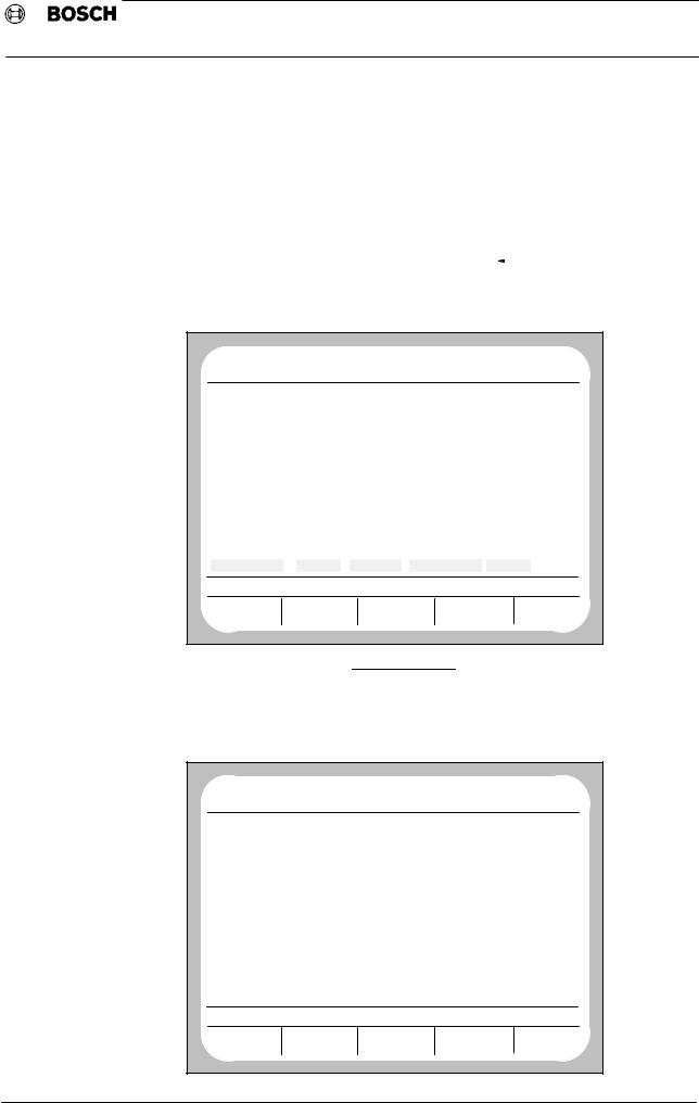
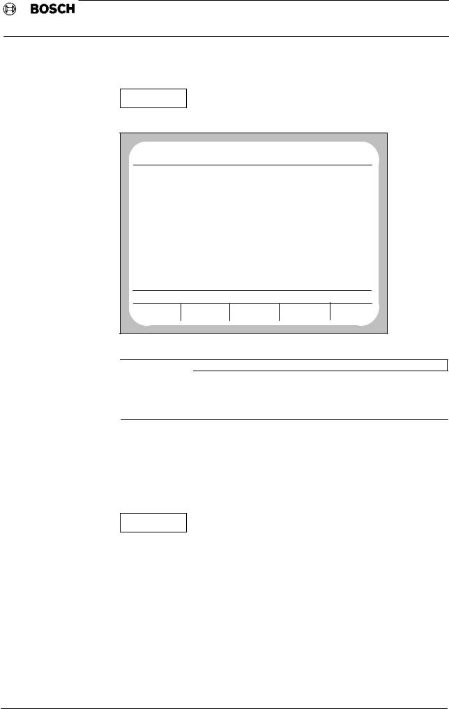
The machine parameters program (MPP) may only be accessed in DIAGNOSTIC operating mode.
This operating mode is selected by pressing 
The following display appears on screen:
NO |
BF0 |
NC0 |
|
|
|
|
|
DIAGNOSTIC |
||
PROGRAM |
ACT |
WAITING |
|
|
|
|
24. 3 |
15:25 |
||
ERROR |
|
CONDITION ON |
|
|
STATUS |
|
|
|||
|
|
|
|
G |
1 |
G |
71 |
NO REF. POINTS |
|
|
|
|
G |
90 |
G |
66 |
G |
140 |
DRIVES ON |
|
|
|
|
G |
94 |
G |
40 |
G |
7 |
FEED STOP |
|
|
|
|
G |
17 |
G |
8 |
G |
27 |
|
|
|
|
|
G |
15 |
G |
29 |
G |
79 |
|
|
|
|
|
G |
80 |
G |
130 |
G |
53 |
|
|
|
|
|
G |
153 |
G |
253 |
G |
67 |
|
|
|
|
|
G |
39 |
G |
62 |
G |
97 |
|
|
|
|
|
G |
65 |
G |
68 |
G |
99 |
|
|
|
|
|
G |
146 |
G |
115 |
G |
167 |
|
|
|
|
|
G |
994 |
|
|
|
|
|
|
|
LAST PROGRAMMED |
|
|
|
|
|
|
|
|
|
|
F 100.0 |
S |
0 |
|
T 1016 |
|
M |
30 |
B |
0 |
|
DIAGNOSTIC |
DIAGNOSTIC |
RESET |
|
SERVICE |
|
|
||||
CONTROL |
MACHINE |
|
FUNCTION |
|
FUNCTION |
|
|
|||
By actuating the softkey  and − if requested to do so by the system − inputting a code number, an overview of all currently resident diagnostic programs (D) may be obtained.
NO |
|
BF0 |
NC0 |
|
DIAGNOSTIC |
|||
PROGRAM |
|
ACT |
WAITING |
|
24. 3 |
15:25 |
||
NUMBER |
|
|
|
NAME OF PROGRAM |
LENGTH |
|
ACCESS |
|
D |
1 |
LOGBOOK MONITOR |
|
|
|
E |
||
D |
2 |
RELOAD OPERATING PROGRAM |
|
|
E |
|||
D |
3 |
CLEAR ALL MEMORY |
|
|
|
E |
||
D |
4 |
MACHINE PARAMETER PROGRAM |
|
|
E |
|||
D |
5 |
INTERNAL REF. POINT OFFSET |
|
|
E |
|||
D |
6 |
SERIAL IF DATA |
|
|
|
E |
||
D |
7 |
COMMUNICATION STORAGE DISPLAY |
|
|
E |
|||
D |
9 |
MANAGE EEPROM |
|
|
|
E |
||
D |
21 |
LOGIC ANALYSER |
|
|
|
E |
||
D |
22 |
AXIS OSCIL. |
|
|
|
E |
||
D |
23 |
CONTOUR DISPLAY |
|
|
|
E |
||
D |
24 |
AXIS OPTIMISATION |
|
|
|
E |
||
MEMORY USED BY DIAGNOSTIC |
4156 |
OTHERS: |
|
72042 |
||||
MEMORY AVAILABLE |
: |
|
185946 |
|
|
|
||
SERVICE FUNCTION |
|
|
|
|
|
|
||
|
|
|
LOAD |
|
OUTPUT |
START |
DELETE |
|
|
|
|
|
− 3 |
− |
|
|
|
Operation
Type1 osa / CC 220
Machine parameters
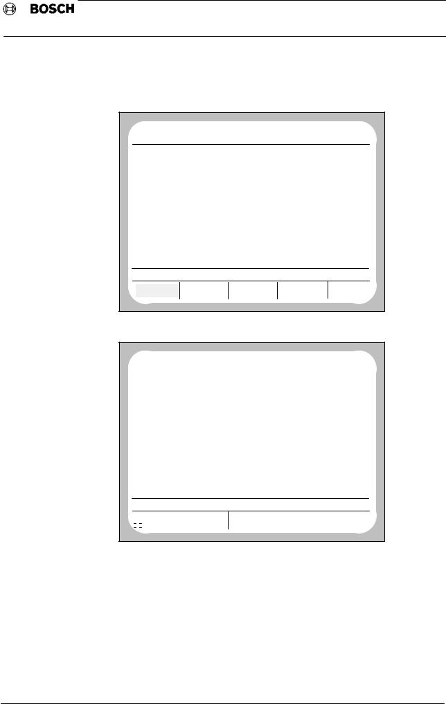
By pressing the softkey
START
and inputting program number 4, the machine parameter program may be started.
NO |
|
BF0 |
NC0 |
|
|
DIAGNOSTIC |
||
PROGRAM |
|
ACT |
WAITING |
|
|
24. 3 |
15:25 |
|
NUMBER |
|
|
NAME OF PROGRAM |
LENGTH |
ACCESS |
|||
L |
870 |
USER<−HEAP<−BLOCK.................... |
|
4140 |
|
|||
L |
1 |
NC LINK TABLE |
|
|
152 |
RWED |
||
L |
2 |
NC LINK TABLE |
|
|
152 |
RWED |
||
L |
3 |
NC LINK TABLE |
|
|
152 |
RWED |
||
L |
4 |
NC LINK TABLE |
|
|
152 |
RWED |
||
L |
5 |
NC LINK TABLE |
|
|
152 |
RWED |
||
L |
444 |
MACHINE PARAMETERS |
24.03 |
|
23319 |
RWED |
||
MEMORY USED BY SYSTEM |
28219 |
OTHERS: |
|
34690 |
||||
MEMORY AVAILABLE |
: |
330307 |
|
|
|
|||
MACHINE PARAMETERS PROGRAM |
|
|
|
|
||||
EDIT |
|
|
LOAD |
TRANSFER |
OUTPUT |
MANAGE |
||
 IMPORTANT
The files •NC LINK TABLE" and •USER<−HEAP<−BLOCK" have no connection with the MPP. L444 only appears if the MP has already been edited or output at least once.
If on selecting DIAGNOSTIC operating mode, the softkey line
|
|
|
|
|
|
DIAGNOSTIC |
DIAGNOSTIC |
RESET |
SERVICE |
MPP |
|
CONTROL |
MACHINE |
FUNCTION |
FUNCTION |
||
|
is displayed, including the •MPP" softkey, pressing the softkey
MPP
is all that is needed to reach the •Machine parameters program"
operating level.
− 4 −

Operation
Type1 osa / CC 220
Machine parameters
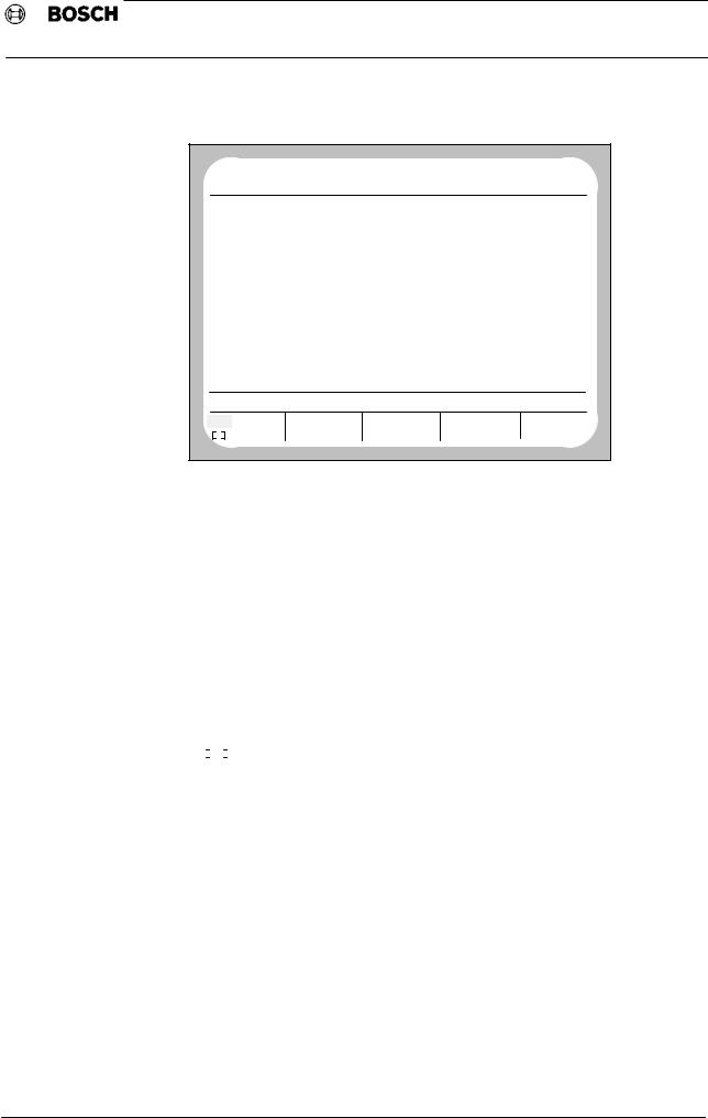
4.2 Editing (modifying)
 IMPORTANT
Only data which is NOT enclosed in square brackets may be edited!
If the parameters are to be edited for the first time, the following display will normally appear (link tables are only present if programs were linked together beforehand):
NO |
|
BF0 |
NC0 |
|
DIAGNOSTIC |
||
PROGRAM |
|
ACT |
WAITING |
|
24. 3 |
15:25 |
|
NUMBER |
|
|
NAME OF PROGRAM |
LENGTH |
ACCESS |
||
L |
870 |
USER<−HEAP<−BLOCK.................... |
|
4140 |
|
||
L |
1 |
NC LINK TABLE |
|
152 |
RWED |
||
L |
2 |
NC LINK TABLE |
|
152 |
RWED |
||
L |
3 |
NC LINK TABLE |
|
152 |
RWED |
||
L |
4 |
NC LINK TABLE |
|
152 |
RWED |
||
L |
5 |
NC LINK TABLE |
|
152 |
RWED |
||
MEMORY USED BY SYSTEM |
4900 |
OTHERS: |
|
34690 |
|||
MEMORY AVAILABLE |
: |
330307 |
|
|
|
||
MACHINE PARAMETERS PROGRAM |
|
|
|
||||
EDIT |
|
|
LOAD |
TRANSFER |
OUTPUT |
MANAGE |
|
|
|
|
|
EDIT |
|
|
|
By pressing the softkey |
|
the following operating level is reached |
|
NO |
|
BF0 |
NC0 |
|
DIAGNOSTIC |
||
PROGRAM |
ACT |
WAITING |
|
24. 3 |
15:25 |
||
|
NUMBER |
|
|
NAME OF PROGRAM |
LENGTH |
ACCESS |
|
L |
870 |
USER<−HEAP<−BLOCK.................... |
4140 |
|
|||
L |
1 |
NC LINK TABLE |
|
152 |
RWED |
||
L |
2 |
NC LINK TABLE |
|
152 |
RWED |
||
L |
3 |
NC LINK TABLE |
|
152 |
RWED |
||
L |
4 |
NC LINK TABLE |
|
152 |
RWED |
||
L |
5 |
NC LINK TABLE |
|
152 |
RWED |
||
MEMORY USED BY SYSTEM |
|
4900 |
OTHERS: |
58009 |
|||
MEMORY AVAILABLE |
: |
|
330307 |
|
|
||
MACHINE PARAMETERS PROGRAM |
|
|
|
||||
|
|
WITH TEXT |
WITHOUT TEXT |
|
|
||
By using the soft keys, the L444 machine parameters file can be generated with or without text. This soft key bar only appears if L444 does not yet exist or has been deleted.
− 5 −
Operation
Type1 osa / CC 220
Machine parameters
After pressing one of the two soft keys, a message appears on screen indicating that the file is being generated. The control generates L444 from the default or application values stored in system memory.
NO |
|
BF0 |
NC0 |
|
DIAGNOSTIC |
||
PROGRAM |
|
ACT |
WAITING |
|
24. 3 |
15:25 |
|
NUMBER |
|
|
NAME OF PROGRAM |
LENGTH |
ACCESS |
||
L |
870 |
USER<−HEAP<−BLOCK.................... |
|
4140 |
|
||
L |
1 |
NC LINK TABLE |
|
152 |
RWED |
||
L |
2 |
NC LINK TABLE |
|
152 |
RWED |
||
L |
3 |
NC LINK TABLE |
|
152 |
RWED |
||
L |
4 |
NC LINK TABLE |
|
152 |
RWED |
||
L |
5 |
NC LINK TABLE |
|
152 |
RWED |
||
MEMORY USED BY SYSTEM |
4900 |
OTHERS: |
|
58009 |
|||
MEMORY AVAILABLE |
: |
330307 |
|
|
|
||
PLEASE WAIT: FILE BEING GENERATED, SET 3500 |
|
|
|
||||
EDIT |
|
LOAD |
TRANSFER |
OUTPUT |
MANAGE |
||
Once file L444 has been generated, the following display appears:
NO |
BF0 |
NC0 |
DIAGNOSTIC |
PROGRAM |
ACT |
WAITING |
24. 3 15:25 |
OPTIONS
B O S C H CC220 BASIC FUNCTIONS MEMORY 224 (+32) K−BYTE
CLIENT EPROM 2048 K−BYTE
THREAD CUTTING INCL. G95 THREAD MILLING
FEED FORWARD CONTROL ACCELERATION PROGRAMMING LOOP FACTOR PROGRAMMING
CORNER DECELERATION/ACCELERATION 16 STANDARD LIMIT SWITCHES IF
4 FAST LIMIT SWITCHES IF
SOFTWARE LIMIT SWITCHES SUPPRESSED 3 ADDITIONAL AUXILIARY FUNCTIONS PROGRAMMABLE SPINDLE ORIENTATION EXTERNAL PROGRAM SELECTION
LEAD SCREW ERROR COMPENSATION CPL WITH GRAPHIC COMMANDS
DNC INTERFACE WITH SIMPLE PROTOCOL
EDIT |
L |
444 |
|
YES |
NO |
A D G J M |
|
|
|
|
$ LF |
P S V Y |
|
|
|
||
B E H K N |
C F I L O |
FUNCTIONS |
|
Q T W Y |
R U X |
||
|
All active options are listed before an overview of the machine parameter sets is displayed.
− 6 −
Operation
Type1 osa / CC 220
Machine parameters
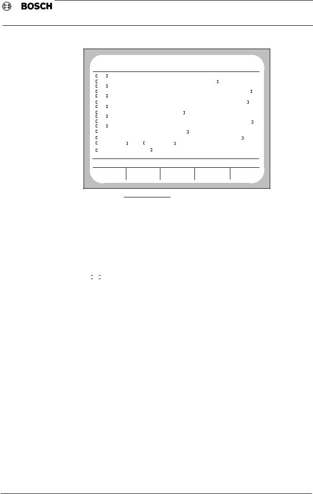
Example of a machine parameters file (L444) with text
NO |
|
BF0 |
NC0 |
|
DIAGNOSTIC |
|
PROGRAM |
ACT |
WAITING |
|
24. 3 |
15:25 |
|
MACHINE PARAMETER SETS |
|
|
|
|||
P |
100 |
A X I S P A R A M E T E R S |
|
|
||
P |
500 |
S P E E D S |
|
|
|
|
P |
1000 |
A X I S D Y N A M I C S |
|
|
|
|
P |
1500 |
P O S I T I O N S |
|
|
|
|
P |
2000 |
A U X I L I A R Y F U N C T I O N S |
|
|
||
P |
2500 |
P O T E N T I O M E T E R S |
|
|
||
P |
3000 |
P O W E R − U P S T A T E |
|
|
||
P |
3500 |
C O L O U R S E T T I N G S |
|
|
||
P |
4000 |
C P L − P A R A M E T E R S |
|
|
||
P |
4500 |
Z E R O S H I F T S |
|
|
|
|
P |
5000 |
S U P P R E S S I O N T A B L E |
|
|
||
P |
5500 |
D E V I C E S E L E C T I O N |
|
|
||
P |
6000 |
P L C P A R A M E T E R S |
|
|
||
P |
6100 |
E L E C T R: L I M I T S W I T C H N O R M A L |
|
|||
P |
6200 |
E L E C T R: L I M I T S W I T C H F A S T |
|
|
||
P |
6500 |
T O O L C O M P E N S A T I O N S |
|
|
||
EDIT |
L |
|
444 |
|
|
|
YES |
NO |
A D G J M |
|
B E H K N |
C F I L O |
|
|
|
|
|
Q T W Y |
FUNCTIONS |
|
|
$ LF |
P S V Y |
|
R U X |
|
|
4.2.1 Input
If there is already a keyboard available (e.g. with Type1 osa keyboard), then characters are selected via the keyboard (SK:Keyboard available is in reverse video; see chapter 4.2.5), and the highest level of the editor appears as follows:
EDIT |
L |
444 |
|
|
DELETE |
SEARCH |
POSITION |
|
FUNCTIONS |
CURSOR |
|
|||
|
|
|
|
The softkey bar
EDIT |
|
L |
444 |
|
|
||
|
|
|
|
|
|
|
|
|
YES |
NO |
A D G J M |
B E H K N |
C F I L O |
FUNCTIONS |
|
|
|
|
$ LF |
P S V Y |
Q T W Z |
R U X |
|
|
|
|
|||||
|
|
|
|
|
|
|
|
identifies the highest editor level if no keyboard is available or the softkey Keyboard available is not in reverse video (see chapter 4.2.5).
At this level, it is possible to input any of the alphabetic characters displayed.
It is possible to insert the softkey character displayed in reverse video into the MP file by pressing the RETURN key.
By pressing a soft key repeatedly, the characters which can be selected from this menu are displayed in reverse video one after the other.
The cursor indicates the point at which any characters entered are inserted into the file.
− 7 −
Operation
Type1 osa / CC 220
Machine parameters
4.2.2 Cursor functions
The cursor can be moved anywhere on the screen using the cursor keys. In addition, the cursor can be placed in certain positions, which must be specified.
Position cursor
Starting at operating level
EDIT |
|
L |
444 |
|
|
||
|
YES |
NO |
A D G J M |
B E H K N |
C F I L O |
FUNCTIONS |
|
|
|
|
$ LF |
P S V Y |
Q T W Z |
R U X |
|
|
|
|
|||||
|
|
|
|
|
|
|
|
by selecting
FUNCTIONS |
|
POSITION |
|
and then selecting |
CURSOR |
||
|
|||
reached. |
|
||
|
|
the operating level is
EDIT |
L |
444 |
|
|
|
|||
RETURN |
BLOCK |
|
WORD |
8 LINES |
* DOWN |
|
||
|
UP |
|
||||||
|
|
|
|
|
|
|
|
|
|
|
|
|
|
|
|
|
|
By selecting |
|
|
BLOCK |
the cursor always jumps to the start of a new line. |
||||
|
|
|
||||||
|
|
|
||||||
|
|
|
|
|
|
|
|
|
By selecting |
|
WORD |
the cursor jumps to the first character of the next |
|||||
|
|
|||||||
|
|
|||||||
word. |
|
|
|
|
|
|
||
|
|
|
|
|
|
|
|
|
By selecting |
|
|
8 LINES |
the cursor always jumps down 8 lines. |
||||
|
|
|||||||
|
|
|||||||
By selecting the •down/up" softkey, the cursor functions become effective towards the end/start of the file.
Press |
RETURN |
|
to return to operating level |
|
|
||||||
|
|
|
|
|
|||||||
|
|
|
|
|
|||||||
|
|
|
|
|
|
|
|
|
|
|
|
EDIT |
|
|
|
L |
444 |
|
|
|
|||
|
YES |
|
NO |
|
A D G J M |
B E H K N |
|
C F I L O |
FUNCTIONS |
||
|
|
|
|
$ LF |
|
P S V Y |
Q T W Z |
|
R U X |
||
|
|
|
|
|
|
||||||
|
|
|
|
|
|
|
|
|
|
|
|
Scroll
The screen display can be scrolled up and down line by line using the cursor keys.
− 8 −

Operation
Type1 osa / CC 220
Machine parameters
4.2.3 Search
It is possible to carry out searches for specific individual terms in the editor.
EDIT |
|
|
|
L |
444 |
|
|
|
||||
|
YES |
NO |
|
A D G J M |
|
B E H K N |
C F I L O |
FUNCTIONS |
|
|||
|
|
|
$ LF |
|
P S V Y |
|
Q T W Z |
R U X |
|
|||
|
|
|
|
|
|
|||||||
|
|
|
|
|
|
|
|
|
|
|
|
|
|
|
|
|
|
|
|
|
|
|
|
||
The softkey |
|
FUNCTIONS |
|
should be pressed at the highest operating level of |
||||||||
|
|
|
|
|||||||||
|
|
|
|
|||||||||
the editor.
This initiates the transition to the next operating level.
EDIT |
L |
444 |
|
|
||
DELETE |
SEARCH |
|
POSITION |
|
FUNCTIONS |
|
|
CURSOR |
|
||||
|
|
|
|
|
|
|
|
|
|
|
|
|
|
By selecting |
|
SEARCH |
the following display is reached: |
|
||
|
|
|
||||
|
|
|
||||
|
|
|
|
|
||
EDIT |
L |
444 |
|
|
||
RETURN |
DEFINE |
|
SEARCH FOR |
END |
*DOWN |
|
STRING |
|
STRING |
UP |
|||
|
|
|
|
|||
Direction of search
The direction of search must be determined before specifying the string to be searched for.
This can be done by pressing
* DOWN
UP .
The asterisk indicates the active direction.
The softkey END is displayed if search direction DOWN is selected, and allows a jump directly to the end of MP file L444.
The softkey START appears if search direction UP is active, and allows a jump directly to the beginning of MP file L444.
The softkey RETURN allows a jump back into the highest level of the editor.
Searching for character strings
|
DEFINE |
By pressing |
STRING |
|
the following softkey bar appears:
EDIT |
|
|
|
L |
444 |
SEARCH FOR : P3500 |
|
|||
|
YES |
NO |
|
A D G J M |
B E H K N |
C F I L O |
|
READY |
||
|
|
|
$ LF |
|
P |
S V Y |
Q T W Z |
R U X |
|
|
|
|
|
|
|
||||||
|
|
|
|
|
|
|
|
|
|
|
The character string to be searched for may now be entered. Every single letter must be confirmed by pressing <ENTER>. Numbers are entered directly via the appropriate keys and cannot/need not be confirmed by pressing <ENTER>.
The |
READY |
function initiates the search procedure. The cursor jumps to |
the searched for location.
− 9 −
|
|
Operation |
Type1 osa / CC 220 |
|
|
|
Machine parameters |
||
|
|
|
|
|
NO |
|
BF0 |
NC0 |
DIAGNOSTIC |
PROGRAM |
ACT |
WAITING |
24. 3 15:25 |
|
− |
62 |
|
|
|
P3009 FEED COMPENSATION ON/OFF (G64/G65) |
|
|||
− |
65 |
|
|
|
P3010 OUTSIDE CORNERS AS A RADIUS OR INTERSECTION (G68(69) |
|
|||
− |
68 |
|
|
|
P3011 TOOL TABLE COMPENSATION ON/OFF (G145/G46) |
|
|||
− |
146 |
|
|
|
P3012 FEED FORWARD CONTROL (G114/G115) |
|
|||
− |
115 |
|
|
|
P3013 EXTERNAL ZERO SHIFT ON/OFF (G160/G167) |
|
|||
− |
167 |
|
|
|
P3500 C O L O U R S E T T I N G S |
|
|||
P3501 COLOUR "AREA" (FOREGROUND AND BACKGROUND) |
|
|||
FOREGROUND |
BLACK |
BACKGROUND LIGHT BLUE |
|
|
P3502 COLOUR "SOFTKEY" |
|
|||
FOUND |
|
|
|
|
EDIT |
|
L |
444 |
|
RETURN |
DEFINE |
SEARCH |
*DOWN |
|
STRING |
END |
UP |
||
|
|
STRING |
||
By pressing  the search for the specified search word is continued in the remaining program text, starting at the current location. The message •STRING NOT FOUND" appears if the sought for character string is not found in the active search direction.
The softkey RETURN can be pressed to jump back to the highest operating level.
|
EDIT |
|
L |
444 |
|
|
||
|
|
|
|
|
|
|
|
|
|
YES |
|
NO |
A D G J M |
B E H K N |
C F I L O |
FUNCTIONS |
|
|
|
|
|
$ LF |
P S V Y |
Q T W Z |
R U X |
|
|
|
|
|
|||||
|
|
|
|
|
|
|
|
|
− 10 −

Operation
Type1 osa / CC 220
Machine parameters
4.2.4 Delete / Undelete
Starting at operating level
EDIT |
|
L |
444 |
|
|
|
|
|||
DELETE |
|
SEARCH |
|
POSITION |
|
FUNCTIONS |
|
|||
|
|
CURSOR |
|
|
||||||
|
|
|
|
|
|
|
|
|||
|
|
|
|
|
|
|
|
|
|
|
by pressing the softkey |
DELETE |
|
|
the following operating level is reached: |
||||||
|
|
|
||||||||
|
|
|
||||||||
|
|
|
|
|
|
|
|
|
||
EDIT |
|
L |
444 |
|
|
|
|
|||
RETURN |
|
DELETE |
|
|
DELETE |
DELETE |
*DELETE |
|
||
|
BLOCK |
|
|
WORD |
CHARACTER |
UNDELETE |
|
|||
|
|
|
|
|
||||||
|
|
|
|
|
|
|
|
|
|
|
|
|
|
DELETE |
|
|
|
|
|
|
|
Pressing the softkey |
|
BLOCK |
|
deletes the line in the machine parameters |
||||||
|
|
|
|
|||||||
file at the beginning of which the cursor is positioned. If the cursor is positioned in the middle of a line, the remainder of the line (after the cursor) is deleted.
Pressing the softkey positioned.
DELETE |
|
CHARACTER |
deletes the character on which the cursor is |
|
Placing the cursor on the first letter of a word and pressing |
|
de |
|
letes the word. The cursor must be positioned on a word.
After deleting a line or character, the procedure can be reversed and the text can be restored to its original condition (undeleting).
|
|
|
|
DELETE |
|
|
|
|
|
This is achieved by pressing |
the |
|
*UNDELETE |
|
softkey. The softkey bar |
||||
|
|
|
|
||||||
changes to |
|
|
|
|
|
|
|
|
|
|
|
|
|
|
|
|
|
||
EDIT |
L |
444 |
|
|
|
|
|
||
RETURN |
UNDELETE |
|
UNDELETE |
|
UNDELETE |
DELETE |
|
||
BLOCK |
|
|
WORD |
|
CHARACTER |
*UNDELETE |
|
||
|
|
|
|
|
|||||
The last item to be deleted (line, word, character) is always stored in an intermediate buffer.
|
UNDELETE |
|
UNDELETE |
|
UNDELETE |
By pressing |
BLOCK |
or |
CHARACTER |
or |
WORD |
|
|
|
the contents of this buffer memory (i.e. the last item to be deleted) is inserted back into the MP file. The cursor indicates the position at which the text will be reinserted.
− 11 −

Operation
Type1 osa / CC 220
Machine parameters
4.2.5 Additional functions
Starting at highest editor operating level
EDIT |
|
L |
444 |
|
|
|||||
|
YES |
|
NO |
A D G J M |
B E H K N |
C F I L O |
FUNCTIONS |
|||
|
|
|
|
$ LF |
P S V Y |
Q T W Z |
R U X |
|||
|
|
|
|
|||||||
|
|
|
|
|
|
|
|
|
|
|
|
|
|
|
|
|
|
|
|
||
and pressing the softkey |
FUNCTIONS |
twice, the following level is reached |
||||||||
|
|
|||||||||
|
|
|||||||||
|
|
|
|
|
|
|
||||
EDIT |
|
L |
444 |
|
|
|
||||
|
|
|
RETURN |
|
|
|
|
ABORT |
FUNCTIONS |
|
|
|
|
|
|
|
|
|
|
|
|
 IMPORTANT
If the MP file (L444) is not being edited, an additional softkey is displayed entitled
INSERT FILE. This has no significance for the MP file.
Press |
|
RETURN |
|
|
|
|
|
to return to the original operating level. |
|
|
||||||||||
|
|
|
|
|
|
|
|
|
|
|
||||||||||
|
|
|
|
|
|
|
||||||||||||||
|
|
|
|
|
|
|
|
|
|
|
|
|
|
|
|
|
|
|
|
|
Press |
|
|
ABORT |
|
|
|
|
|
to leave the editor. The system ignores all data edited up to |
|||||||||||
|
|
|
|
|
|
|
|
|
||||||||||||
|
|
|
|
|
||||||||||||||||
this moment and jumps to the level: |
|
|
|
|
||||||||||||||||
|
|
|
|
|
|
|
|
|
|
|
|
|
|
|
|
|||||
MACHINE PARAMETERS PROGRAM |
|
|
|
|
|
|
||||||||||||||
|
|
EDIT |
|
LOAD |
|
|
|
TRANSFER |
OUTPUT |
|
MANAGE |
|
||||||||
|
|
|
|
|
|
|
|
|
|
|
|
|
|
|
|
|
|
|
||
|
|
|
|
|
|
|
|
|
|
|
|
|
|
|
|
|
||||
Select |
FUNCTIONS |
|
|
again to switch to operating level: |
|
|
||||||||||||||
|
|
|
|
|
|
|
|
|
|
|||||||||||
|
|
|
|
|
|
|
|
|
||||||||||||
|
|
|
|
|
|
|
|
|
|
|
|
|
|
|
||||||
|
|
|
|
|
|
|
|
|
|
|
|
|
|
|
|
|
|
|
|
|
DELETE |
|
|
*M30 |
|
|
|
SECTION |
CALCULATE |
|
FUNCTIONS |
|
|||||||||
TO EOL |
|
INSERT |
|
|
|
|
|
|||||||||||||
|
|
|
|
|
|
|
|
|
|
|||||||||||
|
|
|
|
|
|
|
|
|
|
|
|
|
|
|
|
|
|
|||
|
|
|
|
|
|
|
|
|
|
|
|
|
|
|
|
|
|
|||
|
|
|
|
|
|
DELETE |
|
|
|
|
|
|
|
|
|
|||||
The softkey |
|
|
TO EOL |
|
deletes all characters from the current cursor |
|||||||||||||||
|
|
|
|
|
|
|
|
|||||||||||||
position until the end of the line. |
|
|
|
|
|
|
||||||||||||||
(The deleted sequence may be restored via •UNDELETE BLOCK"). |
|
|
||||||||||||||||||
|
|
|
|
|
|
|
|
|
|
|
|
|
|
|
|
|
|
|
||
|
|
|
|
|
|
|
|
|
|
|
|
*M30 |
|
|
|
|
|
|
||
Ensure that the softkey |
|
|
|
|
INSERT |
|
is in reverse video. This is the only way to |
|||||||||||||
|
|
|
|
|
|
|||||||||||||||
|
|
|
|
|
|
|||||||||||||||
guarantee that an M30 is automatically positioned at the end of the MP file after editing. Without the M30 the MP file cannot be transferred to the operating system.
The |
CALCULATE |
function allows the calculation of a numerical value to be |
entered, by using arithmetical operations.
The •dot before dash" rule applies. Intermediate results are not stored. The result appears at the current cursor position if •ENTER" is pressed.
− 12 −

Operation
Type1 osa / CC 220
Machine parameters
Press |
FUNCTIONS |
to reach the next softkey level. |
|
|||
|
|
|
||||
|
|
|
||||
|
|
|
|
|
|
|
|
|
|
|
|
|
|
|
|
CHANGE |
|
KEYBOARD |
RETURN |
|
|
|
WORD |
|
AVAILABLE |
||
|
|
|
|
|||
|
|
|
|
|
|
|
If the  function is in reverse video, then text and numbers are entered using the keyboard (e.g. Type1 osa keyboard). Text and numbers can also be entered using the five softkeys if this softkey is not displayed in reverse video.
− 13 −
Operation
Type1 osa / CC 220
Machine parameters
4.3 Transfer
By jumping back through the levels from the editor the following operating level may be reached
MACHINE PARAMETERS PROGRAM
EDIT |
LOAD |
TRANSFER |
OUTPUT |
MANAGE |
|
|
|
|
|
The edited machine parameters are only transferred to the operating system in the
form of an internal data record by pressing the |
TRANSFER |
softkey. The |
|
||
|
operating system is then restarted. Once the machine parameters have been transfered, file L444 can be deleted and the appropriate memory area made reavailable via •CONTROL REST". L444 is only required in order to edit or output the machine parameters.
The machine parameters are not automatically transferred into the EEPROMs on the memory card. This can only be done by using diagnostic program 9 •EEPROM MANAGEMENT" (see 4.7).
 NOTE
NOTE
The CNC power supply must not be interrupted during transfer of machine parameters!
Error detection
If an error is detected during the transfer process, the faulty line in the MP file is displayed on screen under the message •INCORRECT MACHINE PARAMETER", and the error displayed in reverse video. In addition, an error message appears in the command line.
The transfer is aborted.
Possible error messages
−Machine parameters are missing:
File L 444, which is to be transferred or deleted, does not exist.
−Invalid application data:
May have been edited by mistake.
Remedy: delete L 444 and read in again/regenerate.
−Memory full:
Not enough memory for L 444.
Remedy: control reset or delete other files + control reset.
−Too many or invalid characters:
A parameter contains more than ten characters or an invalid character.
−Invalid block number:
The previous parameter block may be missing in L 444.
−Invalid value:
A parameter value does not fall within the valid range of values.
−Invalid relationship with block XXX:
Inpermissible parameter combinations.
−Interruption of transfer:
During the transfer, the file is •read through" a total of three times. During the
first two passes, the process can be interrupted by changing operating mode or moving back to another level.
If no error is detected, the operating system is restarted.
− 14 −
Operation
Type1 osa / CC 220
Machine parameters
4.4 Delete
By pressing the |
MANAGE |
and |
DELETE |
softkeys, the entire |
|
|
|||
|
|
edited machine parameters file (L444) is deleted without any further request for confirmation. The •DELETE" function has no effect on machine parameters data stored in system memory.
4.5 Load (CC 220 / Type1 osa)
Loading with CC 220:
By pressing the softkey |
|
LOAD |
the following operating level is reached: |
|||||
|
|
|
||||||
|
|
|
||||||
|
|
|
|
|
|
|
|
|
LOAD |
|
|
|
|
|
|
|
|
*SELECT |
*STATUS |
|
FILE |
SEARCH FOR |
START |
|
||
DEVICES |
|
NUMBER |
DFS FILE |
|
||||
|
|
|
|
|
||||
|
*SELECT |
The softkey |
DEVICES |
|
accesses the operating level
LOAD, *SELECT DEVICES, V24.2
*INTER |
*DCR |
*DCR |
*CCDISK |
*XTRANS |
FACE |
4800 BAUD |
9600 BAUD |
9600 BAUD |
9600 BAUD |
The transfer rate most appropriate to the device must be selected. The active baud rate is displayed in reverse video.
*INTER
By pressing FACE selected:
the interface from which data should be loaded is
LOAD, *SELECT DEVICES, *INTERFACE |
|
|
|||
V24. 1 |
V24. 2 |
*DNC CHANNEL |
|
|
|
20 MA |
(Optional) |
|
|
||
|
|
|
|||
|
|
|
|
|
|
Pressing return twice restores the original operating level: |
|
||||
|
|
|
|
|
|
LOAD |
|
|
|
|
|
*SELECT |
*STATUS |
FILE |
SEARCH FOR |
START |
|
DEVICES |
NUMBER |
DFS FILE |
|||
|
|
||||
|
|
|
|
|
|
Handshake with V24.1 / 20mA and V24.2
To transfer data with a software handshake, the
*STATUS |
|
*SOFTWARE |
|
|
and then the |
CONTROL |
should be actuated. |
||
|
||||
|
|
The file is selected by pressing the softkey 
 and entering the number 444 (MP file) or by using the cursor to select.
By pressing the |
START |
softkey, the transfer of the externally stored |
machine parameters file into the CNC is initiated.
− 15 −
Operation
Type1 osa / CC 220
Machine parameters
 IMPORTANT
If *DEVICE CONTROL is used to read out, *DEVICE CONTROL must also be used to read in.
At baud rates < 600 only software handshake is permissible.
The file is selected by pressing the softkey 
 and entering the number L 444 (MP file) or by using the cursor to select.
By pressing the |
START |
softkey, the transfer of the externally stored |
machine parameters file into the CNC is initiated.
Loading with the Type1 osa:
By pressing the |
LOAD |
softkey the following operating level is reached |
|||
|
|||||
|
|||||
|
|
|
|
|
|
LOAD |
|
|
|
|
|
*SELECT |
|
FILE |
SEARCH FOR |
START |
|
DEVICES |
|
NUMBER |
DFS FILE |
|
|
|
|
|
|||
|
*SELECT |
The softkey |
DEVICES |
|
accesses the operating level
LOAD, *SELECT DEVICES, |
PC CHANNEL |
*INTER FACE
The transfer rate most appropriate to the device must be selected, if V24.1/ 20mA is selected (see also CC220).
|
*INTER |
|
Press |
FACE |
to select the interface from which data should be loaded: |
|
The PC channel enables the program (file) to be loaded from the internal hard disk of the Type1 osa PC. Loading is possible from a device with a serial interface via the V24.1 /20mA interface:
LOAD, *SELECT DEVICES, *INTERFACE
V24. 1 |
PC CHANNEL |
|
|
|
20 MA |
|
|
|
|
|
|
|
|
|
|
|
|
|
|
Pressing return twice restores the original operating level:
LOAD |
PC CHANNEL |
|
|
|
*SELECT |
|
FILE |
SEARCH FOR |
START |
DEVICES |
|
NUMBER |
DFS FILE |
|
|
|
|||
Handshake with V24.1 / 20mA
To transfer data with a software handshake, the
*STATUS |
|
*SOFTWARE |
|
|
and |
CONTROL |
softkeys should be actuated. |
||
|
||||
|
|
− 16 −
Operation
Type1 osa / CC 220
Machine parameters
The file is selected by pressing the softkey 
 and entering the number L 444 (MP file) or by using the cursor to select.
By pressing the |
START |
softkey, the transfer of the externally stored |
machine parameters file into the CNC is initiated.
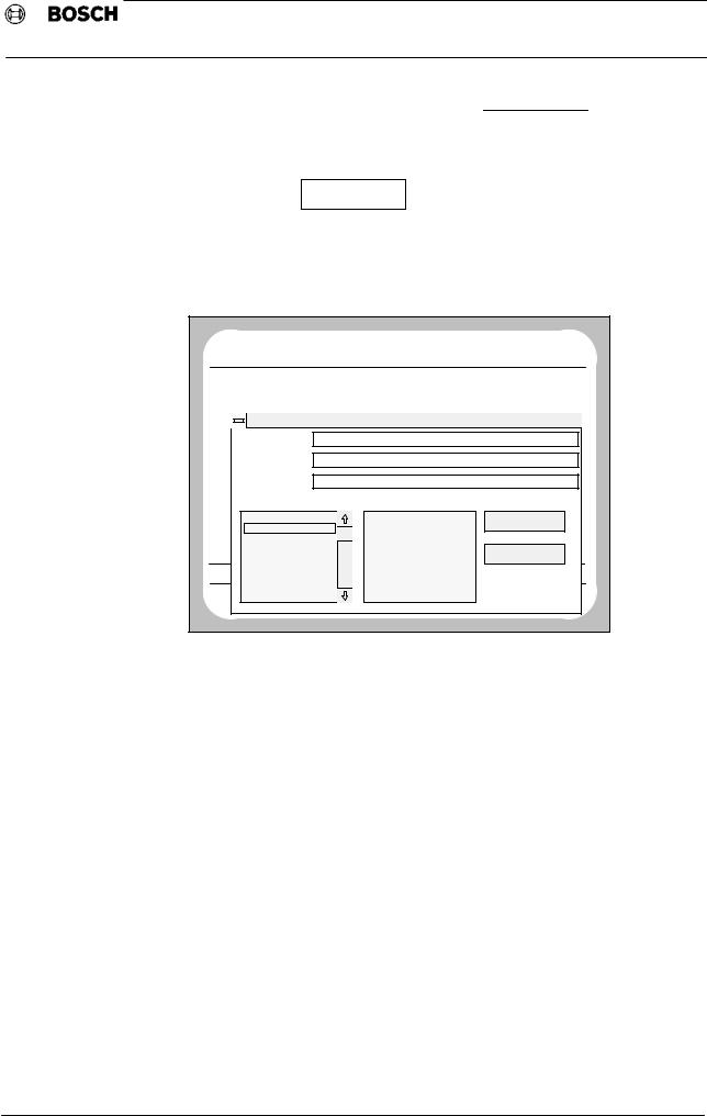
If data are to be transfered from the Type1 osa display to the Type1 osa module, this Load procedure can be controlled via the •Data transfer from PC −> NC" selection window.
NO |
|
BF0 |
NC0 |
|
|
DIAGNOSTIC |
|
PROGRAM |
ACT |
WAITING |
|
|
24. 3 |
15:25 |
|
NUMBER |
|
NAME OF PROGRAM |
LENGTH |
ACCESS |
|||
L |
5 |
NC LINK TABLE |
|
|
152 |
RWED |
|
L |
444 |
MACHINE PARAMETER |
24.03 |
23319 |
RWED |
||
|
|
|
Data transfer from PC −> NC |
|
|
||
|
File |
|
MP010296.txt |
|
|
|
|
|
Path |
|
c:\osa1_ap2 |
|
|
|
|
|
DFS Identifier |
(DFS,L |
444,MACHINE PARAMETER 102,RWED) |
|
|||
|
File: |
|
Path selection: |
|
|
||
|
english.txt |
|
|
[..] |
|
START |
|
|
MP010296.txt |
|
[−a−] |
|
|
||
|
|
|
|
|
|||
MEM |
log2_96.txt |
|
|
[−c−] |
|
|
|
MEM |
Prog1.txt |
|
|
|
|
ABORT |
|
|
Prog2.txt |
|
|
|
|
|
|
MAC |
Prog3.txt |
|
|
|
|
|
|
|
Prog3.txt |
|
|
|
|
|
|
E |
Prog3.txt |
|
|
|
|
|
|
|
|
|
|
|
|
|
|
For a description of the operating sequence, see page 20.
Once all MP data has been transferred or integrated, the machine parameters should be stored in the EEPROM in non volatile form (see 4.3 TRANSFER, or 4.7 MANAGE EEPROM)*
− 17 −
Loading...