


 Loading...
BVMS
en |
Operation manual |

BVMS |
Table of contents | en 3 |
|
|
Table of contents
1 |
Using the Help |
7 |
1.1 |
Finding information |
7 |
1.2 |
Printing the Help |
7 |
2 |
Introduction |
9 |
3 |
|
|
System overview |
11 |
|
3.1 |
Hardware requirements |
12 |
3.2 |
Software requirements |
12 |
3.3 |
License requirements |
12 |
4 |
Concepts |
13 |
4.1 |
BVMS design concepts |
13 |
4.1.1 |
Single Management Server System |
13 |
4.1.2 |
Enterprise System |
14 |
4.1.3 |
Server Lookup |
15 |
4.1.4 |
Unmanaged site |
16 |
4.2 |
Recording |
17 |
4.2.1 |
Automated Network Replenishment (ANR) |
17 |
4.3 |
Alarm handling |
19 |
4.4 |
Inactivity logoff |
20 |
4.5 |
Version independent Operator Client |
21 |
4.5.1 |
Working with Compatibility Mode |
21 |
4.6 |
Viewing modes of a panoramic camera |
22 |
4.6.1 |
360° panoramic camera - flooror ceiling mounted |
22 |
4.6.2 |
180° panoramic camera - flooror ceiling mounted |
24 |
4.6.3 |
360° panoramic camera - wall mounted |
25 |
4.6.4 |
180° panoramic camera - wall mounted |
26 |
4.6.5 |
Cropped view on a panoramic camera |
27 |
4.7 |
SSH Tunneling |
28 |
5 |
Getting started |
29 |
5.1 |
Starting Operator Client |
29 |
5.2 |
Accepting a new configuration |
30 |
5.3 |
Accessing the system |
30 |
5.4 |
Using Server Lookup |
30 |
6 |
Displaying camera images |
32 |
6.1 |
Selecting a time zone |
32 |
6.2 |
Displaying a camera in an Image pane |
33 |
6.3 |
Displaying a panoramic camera |
33 |
6.4 |
Switching the viewing mode of panoramic camera |
34 |
6.5 |
Displaying a dual thermal/optical camera |
34 |
6.6 |
Displaying cameras from multiple Management Servers |
35 |
6.7 |
Finding an item in the Logical Tree |
35 |
6.8 |
Changing the number of Image pane rows |
35 |
6.9 |
Arranging and resizing Image panes |
36 |
6.10 |
Displaying the Alarm Image window |
36 |
6.11 |
Starting manual recording |
37 |
6.12 |
Starting a pre-configured camera sequence |
37 |
6.13 |
Starting an automatic camera sequence |
38 |
6.14 |
Using one channel audio mode |
39 |
6.15 |
Using multichannel audio mode |
39 |
Bosch Security Systems B.V. |
Operation manual |
2020.08 | V 1 | Operator Client |

4 en | Table of contents BVMS
6.16 |
Using digital zoom |
40 |
6.17 |
Saving a single image |
40 |
6.18 |
Printing a single image |
40 |
6.19 |
Switching to full-screen mode |
41 |
6.20 |
Displaying or hiding the Image pane bars |
41 |
6.21 |
Displaying information on a camera |
41 |
6.22 |
Enabling video content analysis (VCA) |
42 |
6.23 |
Showing video content analysis (VCA) rules |
42 |
6.24 |
Starting instant playback |
42 |
6.25 |
Assigning a camera to a monitor |
43 |
6.26 |
Using audio mode |
43 |
6.27 |
Using the Intercom functionality |
43 |
6.28 |
Locking the control of a PTZ camera |
45 |
6.29 |
Updating the reference image |
45 |
6.30 |
Displaying a monitor group |
46 |
6.31 |
Controlling a monitor wall |
46 |
6.32 |
Selecting live stream for display |
47 |
6.33 |
Displaying video via low bandwidth |
47 |
6.34 |
Using TCP for reliable connection |
49 |
6.35 |
Connecting to an unmanaged site |
49 |
6.36 |
Displaying a video analytics alarm |
50 |
6.37 |
Displaying Intelligent Insights widgets |
50 |
7 |
Using maps and the PTZ cameras |
51 |
7.1 |
Displaying a map |
51 |
7.2 |
Controlling PTZ cameras |
51 |
7.3 |
Using in-window control of a camera |
52 |
7.4 |
Using the ROI function |
52 |
7.5 |
Using Intelligent Tracking |
53 |
8 |
Using favorites and bookmarks |
54 |
8.1 |
Adding items to the Favorites Tree |
54 |
8.2 |
Creating/editing views |
55 |
8.3 |
Adding a bookmark |
56 |
8.4 |
Editing a bookmark |
57 |
8.5 |
Loading a bookmark |
57 |
8.6 |
Exporting bookmarks |
57 |
8.6.1 |
Export Bookmark dialog box |
58 |
8.6.2 |
Export Multiple Bookmarks dialog box |
59 |
9 |
Managing recorded videos |
61 |
9.1 |
Selecting a time zone |
61 |
9.2 |
Finding recorded video |
62 |
9.2.1 |
Video Search Results window |
62 |
9.3 |
Playing recorded videos |
63 |
9.4 |
Using the Timeline |
63 |
9.5 |
Changing the playback speed |
63 |
9.6 |
Restricting or unrestricting video |
64 |
9.6.1 |
Restrict Video dialog box |
64 |
9.6.2 |
Unrestrict Video dialog box |
65 |
9.7 |
Protecting or unprotecting video |
65 |
9.7.1 |
Protect Video dialog box |
66 |
2020.08 | V 1 | Operator Client |
Operation manual |
Bosch Security Systems B.V. |

BVMS |
Table of contents | en 5 |
|
|
9.7.2 |
Unprotect Video dialog box |
66 |
9.8 |
Deleting video data |
67 |
9.9 |
Verifying the authenticity of video data |
67 |
9.9.1 |
Authenticity verification result dialog box |
68 |
9.10 |
Exporting video data |
69 |
9.10.1 |
Exporting a time period |
71 |
9.10.2 |
Exporting a single search entry |
71 |
9.10.3 |
Exporting into a single file |
72 |
9.10.4 |
Providing a password for export |
72 |
9.10.5 |
Export Video dialog box |
73 |
9.10.6 |
Export dialog box |
74 |
9.11 |
Loading exported video |
75 |
9.12 |
Enabling video content analysis (VCA) |
75 |
9.13 |
Performing a Forensic Search |
76 |
9.14 |
Forensic Search Results window |
77 |
9.15 |
Finding logbook entries |
77 |
9.15.1 |
Finding logons to an unmanaged site |
78 |
9.15.2 |
Please select a Server |
78 |
9.15.3 |
Select Search Parameters dialog box |
78 |
9.15.4 |
Event Selection dialog box |
82 |
9.15.5 |
Device Selection dialog box |
82 |
9.15.6 |
Search Conditions dialog box |
82 |
9.15.7 |
Logbook Results: dialog box |
82 |
9.16 |
Displaying text data |
83 |
9.17 |
Searching for text data |
84 |
9.18 |
Searching for text data in logbook entries |
85 |
9.19 |
Erasing text data from logbook entries |
85 |
9.20 |
Displaying video via low bandwidth |
86 |
9.21 |
Switching the recording source |
87 |
9.22 |
Connecting to an unmanaged site |
88 |
10 |
Handling events and alarms |
90 |
10.1 |
Accepting an alarm |
90 |
10.2 |
Adding comments to an alarm |
91 |
10.3 |
Clearing an alarm |
91 |
10.4 |
Customizing the Alarm List window |
92 |
10.5 |
Displaying the Live Image window |
92 |
10.6 |
Switching alarm modes of Alarm Image window |
92 |
10.7 |
Starting a workflow |
93 |
10.8 |
Un-accepting an alarm |
93 |
10.9 |
Triggering a user event |
94 |
10.10 |
Alarm List window |
94 |
11 |
Managing Person Identification alarms |
95 |
11.1 |
Managing persons for a Person Identification alarm |
95 |
12 |
Controlling intrusion panel functions |
97 |
12.1 |
Switching off alarm sirens |
97 |
12.2 |
Operating doors |
97 |
12.3 |
Bypassing a point |
97 |
12.3.1 |
Arming an area |
98 |
13 |
Controlling access control functions |
99 |
Bosch Security Systems B.V. |
Operation manual |
2020.08 | V 1 | Operator Client |

6 en | Table of contents BVMS
13.1 |
Granting and denying access |
99 |
13.2 |
Operating doors |
99 |
14 |
Using a CCTV keyboard |
100 |
14.1 |
Using KBD Universal XF keyboard |
100 |
14.1.1 |
KBD Universal XF keyboard user interface |
100 |
14.2 |
Bosch IntuiKey keyboard user interface |
102 |
14.2.1 |
Status display |
103 |
14.3 |
Using a Bosch IntuiKey keyboard connected to a workstation |
103 |
14.3.1 |
Starting the keyboard |
104 |
14.3.2 |
Entering operation modes |
104 |
14.3.3 |
Displaying cameras |
104 |
14.3.4 |
Using the joystick |
105 |
14.3.5 |
Using softkeys |
105 |
14.4 |
Using a Bosch IntuiKey keyboard connected to a decoder |
107 |
14.4.1 |
Starting the keyboard |
107 |
14.4.2 |
Displaying cameras |
108 |
14.4.3 |
Using the joystick |
108 |
14.4.4 |
Using softkeys |
108 |
15 |
User interface |
109 |
15.1 |
Live Mode |
109 |
15.2 |
Playback Mode |
111 |
15.3 |
Alarm Mode (Alarm Display) |
113 |
15.4 |
Icons used |
115 |
15.5 |
Menu commands |
119 |
15.6 |
Options dialog box |
122 |
15.6.1 |
Control tab |
123 |
15.6.2 |
Display tab |
123 |
15.6.3 |
Audio tab |
124 |
15.6.4 |
Transcoding tab |
124 |
15.7 |
Logical Tree window |
124 |
15.8 |
Favorites Tree window |
125 |
15.9 |
Bookmarks window |
125 |
15.10 |
Image window |
126 |
15.11 |
Image pane |
127 |
15.12 |
Search box |
127 |
15.13 |
Exports window |
128 |
15.14 |
Map window |
128 |
15.15 |
Monitor Wall Image window |
128 |
15.16 |
PTZ Control window |
129 |
15.17 |
Timeline window |
130 |
16 |
Keyboard shortcuts |
132 |
16.1 |
General controls |
132 |
16.2 |
Playback controls |
132 |
16.3 |
Image window controls |
132 |
17 |
Troubleshooting |
133 |
17.1 |
Reestablishing the connection to a Bosch IntuiKey keyboard |
134 |
|
Glossary |
135 |
|
|
|
|
Index |
140 |
2020.08 | V 1 | Operator Client |
Operation manual |
Bosch Security Systems B.V. |

BVMS Using the Help | en 7
1 Using the Help
To find out more about how to do something in BVMS, access the online Help using any of the following methods.
To use the Contents, Index, or Search:
4 On the Help menu, click Display Help. Use the buttons and links to navigate.
To get help on a window or dialog:
4 On the toolbar, click  . OR
. OR
4 Press F1 for help on any program window or dialog.
1.1Finding information
You can find information in the Help in several ways.
To find information in the Online Help:
1.On the Help menu, click Help.
2.If the left-hand pane is not visible, click the Show button.
3.In the Help window, do the following:
Click: |
To: |
Contents |
Display the table of contents for the Online Help. Click each book to |
|
display pages that link to topics, and click each page to display the |
|
corresponding topic in the right-hand pane. |
|
|
Index |
Search for specific words or phrases or select from a list of index |
|
keywords. Double-click the keyword to display the corresponding topic |
|
in the right-hand pane. |
|
|
Search |
Locate words or phrases within the content of your topics. Type the |
|
word or phrase in the text field, press ENTER, and select the topic you |
|
want from the list of topics. |
|
|
Texts of the user interface are marked bold.
4 The arrow invites you to click on the underlined text or to click an item in the application.
Related Topics
4Click to display a topic with information on the application window you currently use. This topic provides information on the application window controls.
Concepts, page 13 provides background information on selected issues.
Notice!
This symbol indicates a potential risk of property damage or data loss.
1.2Printing the Help
While using the Online Help, you can print topics and information right from the browser window.
To print a Help topic:
1.Right-click in the right pane and select Print. The Print dialog box opens.
2.Click Print.
Bosch Security Systems B.V. |
Operation manual |
2020.08 | V 1 | Operator Client |

8 en | Using the Help |
BVMS |
|
|
PThe topic is printed to the specified printer.
2020.08 | V 1 | Operator Client |
Operation manual |
Bosch Security Systems B.V. |

BVMS |
Introduction | en 9 |
|
|
2 Introduction
Click the link to access the Open Source Software licenses used by BVMS and the Mobile App: http://www.boschsecurity.com/oss/
Covered by one or more claims of the patents listed at patentlist.hevcadvance.com.
1 |
Menu bar |
Allows you to select a menu command. |
2 |
Toolbar |
Displays the available buttons. Point to an icon to |
|
|
display a tooltip. |
|
|
|
3 |
Playback controls |
Allows you to control instant playback or a camera |
|
|
sequence or alarm sequence. |
4 |
Performance meter |
Displays the CPU usage and the memory usage. |
|
|
|
5 |
Time zone selector |
Select an entry for the time zone to be displayed in |
|
|
most time related fields. |
|
|
Only available if at least one Management Server or |
|
|
unmanaged site in the Logical Tree is located in |
|
|
another time zone as your Operator Client. |
|
|
|
6 |
Controls for Image panes |
Allows you to select the required number of Image |
|
|
panes and to close all Image panes. |
7 |
Image window |
Displays the Image panes. Allows you to arrange the |
|
|
Image panes. |
|
|
|
8 |
Image pane |
Displays a camera, a map, an image, a document |
|
|
(HTML file). |
Bosch Security Systems B.V. |
Operation manual |
2020.08 | V 1 | Operator Client |

10 en | Introduction BVMS
9 |
|
Displays all alarms that the system generates. |
|
Alarm List window |
Allows you to accept or clear an alarm or to start a |
|
workflow, for example, by sending an E-mail to a |
|
|
|
|
|
|
maintenance person. |
|
|
The Alarm List is not being displayed, when the |
|
|
connection to the Management Server is lost. |
|
|
|
10 |
|
Allows you to control a PTZ camera. |
|
PTZ Control window |
|
|
|
|
11 |
|
Displays the devices your user group has access to. |
|
Logical Tree window |
Allows you to select a device for assigning it to an |
|
Image pane. |
|
|
|
|
|
|
|
|
|
Allows you to organize the devices of the Logical Tree |
|
Favorites Tree window |
as required. |
|
|
|
|
|
|
|
Bookmarks window |
Allows to manage bookmarks. |
|
|
|
|
|
Displays a site map. Allows you to drag the map to |
|
Map window |
display a particular section of the map. |
|
If activated, a map is displayed automatically for each |
|
|
|
|
|
|
camera displayed in an Image pane. In this case, the |
|
|
camera must be configured on a map. |
|
|
|
This manual guides you through the basic steps of the configuration and operation with BVMS. For detailed help and step-by-step instructions read the Configuration Manual and the User Manual or use the Online Help.
BVMS Export Player displays exported recordings.
2020.08 | V 1 | Operator Client |
Operation manual |
Bosch Security Systems B.V. |
BVMS System overview | en 11
3 System overview
If you plan to install and configure BVMS, participate in a system training on BVMS.
Refer to the Release Notes of the current BVMS version for supported versions of firmware and hardware and other important information.
See data sheets on Bosch workstations and servers for information on computers where BVMS can be installed.
The BVMS software modules can optionally be installed on one PC.
Important components
Component |
Description |
Management Server (selectable |
Stream management, alarm management, priority |
in Setup) |
management, Management logbook, user management, |
|
device state management. Additional Enterprise System |
|
license: Managing Enterprise User Groups and Enterprise |
|
Accounts. |
|
|
Config Wizard |
Easy and fast setup of a recording system. |
|
|
Configuration Client (selectable |
System configuration and administration for |
in Setup) |
Operator Client. |
|
|
Operator Client (selectable in |
Live monitoring, storage retrieval and playback, alarm and |
Setup) |
accessing multiple Management Server computers |
|
simultaneously. |
|
|
Video Recording Manager |
Distributing storage capacities on iSCSI devices to the |
(selectable in Setup) |
encoders, while handling load balancing between multiple |
|
iSCSI devices. |
|
Streaming playback video and audio data from iSCSI to |
|
Operator Clients. |
Mobile Video Service |
Provides a transcoding service that transcodes the live and |
(selectable in Setup) |
recorded video stream from a camera configured in BVMS |
|
to the available network bandwidth. This service enables |
|
video clients like an iPhone or a Web client to receive |
|
transcoded streams, for example for unreliable network |
|
connections with limited bandwidth. |
|
|
Web Client |
You can access live and playback videos via Web browser. |
|
|
Mobile App |
You can use the Mobile App on iPhone or iPad to access |
|
live and playback video. |
Bosch Video Streaming Gateway |
Provides the integration of 3rd party cameras and NVR-like |
(selectable in Setup) |
recording, e.g. in low-bandwidth networks. |
|
|
Cameo SDK (selectable in |
The Cameo SDK is used to embed BVMS live and playback |
Setup) |
Image panes to your external third-party application. The |
|
Image panes follow the BVMS based user permissions. |
|
The Cameo SDK provides a subset of the BVMS |
|
Operator Client functionalities that enables you to create |
|
applications similar to the Operator Client. |
|
|
Bosch Security Systems B.V. |
Operation manual |
2020.08 | V 1 | Operator Client |

12 en | System overview BVMS
Component |
Description |
Client Enterprise SDK |
The Client Enterprise SDK is meant to control and monitor |
|
the behaviour of Operator Client of an Enterprise System |
|
by external applications. The SDK allows to browse devices |
|
that are accessible by the running, connected |
|
Operator Client and to control some UI functionalities. |
|
|
Client SDK / Server SDK |
The Server SDK is used to control and monitor the |
|
Management Server by scripts and external applications. |
|
You can use those interfaces with a valid administrator |
|
account. |
|
The Client SDK is used to control and monitor the |
|
Operator Client by external applications and scripts (part |
|
of the related server configuration). |
|
|
3.1Hardware requirements
See the data sheet for BVMS. Data sheets for platform PCs are also available.
3.2Software requirements
See the data sheet for BVMS.
3.3License requirements
See the data sheet for BVMS for the available licenses.
2020.08 | V 1 | Operator Client |
Operation manual |
Bosch Security Systems B.V. |

BVMS |
Concepts | en 13 |
|
|
4 Concepts
This chapter provides background information on selected issues.
4.1BVMS design concepts
Single Management Server System, page 13
A single BVMS Management Server System provides management, monitoring and control of up to 2000 cameras/encoders.
Enterprise System, page 14
An Enterprise Management Server provides simultaneous access to multiple Management Servers. The Enterprise System allows full access to events and alarms from multiple subsystems.
Server Lookup, page 15
The Server Lookup feature provides a list of available BVMS Management Servers to the BVMS Operator Client. The Operator can select a server out of the list of available server. Connected to the Management Server the Client has full access to the Management Server.
Unmanaged site, page 16
Devices can be grouped to unmanaged sites. Devices under unmanaged sites are not monitored by the Management Server. The Management Server provides a list of unmanaged sites to the Operator Client. The Operator can connect on demand to the site and gets access to live video data and recorded video data. Event and alarm handling is not available in the unmanaged site concept.
4.1.1Single Management Server System
–A single BVMS Management Server can manage up to 2000 channels.
–A BVMS Management Server provides management, monitoring, and control of the entire system.
–The BVMS Operator Client is connected to the Management Server and receives events and alarms from the BVMS Management Server and shows live and playback.
–In most cases all devices are in one local area network with a high bandwidth and a low
latency.
Responsibilities:
–Configuring data
–Event log (logbook)
–User profiles
–User priorities
–Licensing
–Eventand alarm-management
Live, playback, events, alarms
Bosch Security Systems B.V. |
Operation manual |
2020.08 | V 1 | Operator Client |
14 en | Concepts |
BVMS |
|
|
Management Server
Operator Client / Configuration Client
Cameras
VRM
iSCSI
Other devices
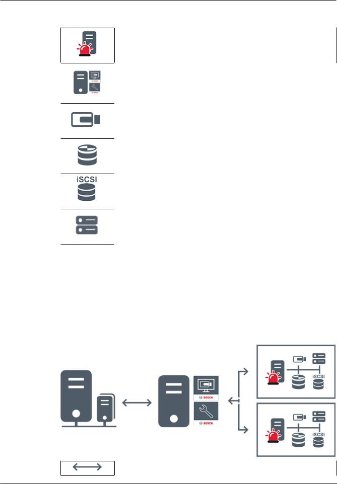
4.1.2Enterprise System
–The target of a BVMS Enterprise System is to enable a user of an Operator Client to simultaneously access multiple Management Servers (subsystems).
–Clients connected to an Enterprise Server have full access to all cameras and recordings from the subsystems.
–Clients connected to an Enterprise Server have full real time awareness of events and alarms of all subsystems.
–Typical application areas:
–Metros
–Airports
Live, playback, events, alarms
2020.08 | V 1 | Operator Client |
Operation manual |
Bosch Security Systems B.V. |

BVMS |
Concepts | en 15 |
|
|
BVMS Enterprise Management Server
BVMS Operator Client / Configuration Client
BVMS Subsystem
Refer to
–Accessing the system, page 30
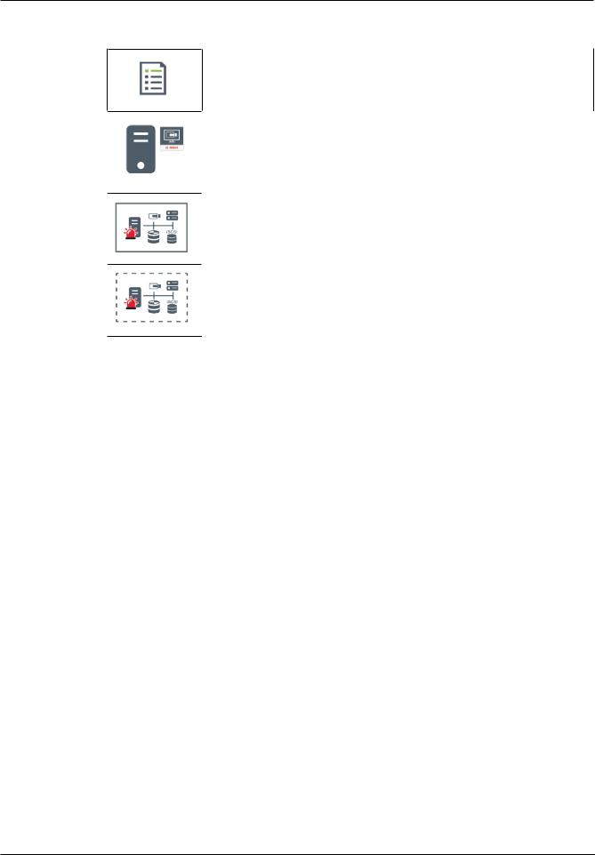
4.1.3Server Lookup
–The BVMS Server Lookup feature allows Operators to connect to a BVMS Management Server out of a provided list of servers.
–A single user of Configuration Client or Operator Client can connect to multiple system access points sequentially.
–System access points can be Management Server or Enterprise Management Server.
–Server Lookup uses dedicated Management Server to host the Server List.
–Server Lookup and Management Server or Enterprise Management Server functionally can be run on one machine.
–Server Lookup supports you in locating system access points by their names or descriptions.
–Once connected to the Management Server the Operator Client receives events and alarms from the BVMS Management Server and shows live and playback
On demand live, playback, events, alarms - connected
On demand live, playback, events, alarms - not connected
Management Server
Bosch Security Systems B.V. |
Operation manual |
2020.08 | V 1 | Operator Client |
16 en | Concepts |
BVMS |
|
|
Server list
Operator Client
Connected BVMS from server list
Not connected BVMS from server list
Refer to
–Using Server Lookup, page 30
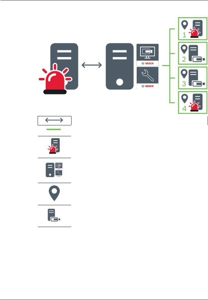
4.1.4Unmanaged site
–A system design option in BVMS with a large number of small subsystems.
–It allows to configure up to 9999 locations in one BVMS Management Server
–Operators can access live and recorded video data from up to 20 sites simultaneously.
–For an easy navigation sites can be grouped in folders or can be placed on maps. Predefined username and password allow operators to quickly connect to a site .
The unmanaged site concept supports IP based BVMS system as well as analog DVR solutions:
–Bosch DIVAR AN 3000 / 5000 analog recorders
–DIVAR hybrid recorders
–DIVAR network recorders
–DIP 3000/7000 units IP based recording
–Single BVMS Management Server System
Adding a site for central monitoring only requires a license per site and is independent of the number of channels in thesite.
2020.08 | V 1 | Operator Client |
Operation manual |
Bosch Security Systems B.V. |
BVMS |
Concepts | en 17 |
|
|
Live, playback, events, alarms
On demand live and playback video traffic
Management Server
Operator Client / Configuration Client
site
DVR
4.2Recording
This chapter explains the different recording and replay related functions in the system.
4.2.1Automated Network Replenishment (ANR)
Intended use
When a failure of the network or the central storage occurs, the ANR function ensures that the encoder transmits the locally buffered recording of the missing time period to the central storage after the failure is fixed.
The following graphic shows the transmission of video data after a network or storage failure is fixed.
Bosch Security Systems B.V. |
Operation manual |
2020.08 | V 1 | Operator Client |

18 en | Concepts |
BVMS |
|
|
1Video
2Encoder, IP network
3SD card (ring buffer)
4iSCSI target (central storage)
Example: Work around network failure
If the network fails unexpectedly, the ANR function completes the central storage with the locally buffered recording when the network is available again.
Example: Store video data when network is not available
A subway has no network connection to the central storage when located between stations. Only during regular stops the buffered recording can be transmitted to the central storage. Ensure that the time period that is required for transferring the buffered recording, does not exceed the time period of a stop.
Example: ANR for alarm recording
The pre-alarm recording is stored locally. Only in case of an alarm, this pre-alarm recording is transmitted to the central storage. If no alarm occurs, the obsolete pre-alarm recording is not transmitted to the central storage and, hence, does not burden the network.
Limitations
Notice!
You cannot use playback from the local storage media when the passwords for `user` and `live` are set on the encoder. Remove the passwords if required.
The ANR function only works with VRM recording.
The ANR function does not work with an encoder for which a secure connection for live display is configured.
You must have configured the storage media of an encoder to use the ANR function.
The encoder for which you configure the ANR function, must have firmware version 5.90 or later. Not all encoder types support the ANR function.
You cannot use the ANR function with dual recording. Your iSCSI storage system must be properly configured.
The following list contains the possible reasons if you cannot configure the ANR function:
–Encoder is not reachable (wrong IP address, network failure, etc.).
–Storage media of the encoder not available or read-only.
–Wrong firmware version.
2020.08 | V 1 | Operator Client |
Operation manual |
Bosch Security Systems B.V. |

BVMS |
Concepts | en 19 |
|
|
–Encoder type does not support the ANR function.
–Dual recording is active.
4.3Alarm handling
Alarms can be individually configured to be handled by one or more user groups. When an alarm occurs, it appears in the Alarm List of all users in the user groups configured to receive that alarm. When any one of these users starts to work on the alarm, it disappears from the Alarm List of all other users.
Alarms are displayed on a workstation’s alarm monitor. This behavior is described in the following paragraphs.
Alarm flow
1.An alarm occurs in the system.
2.Alarm notifications appear in the Alarm Lists of all users configured for this alarm. Alarm video is immediately displayed on configured monitors. If it is an automatically displayed alarm (auto pop-up), the alarm video is also automatically displayed on the
Operator Client workstation’s alarm monitors.
If the alarm is configured as an auto-clear alarm, the alarm is removed from the Alarm List after the auto-clear time (configured in the Configuration Client).
On monitors, any quad views from VIP XDs are temporarily replaced by full-screen displays.
3.One of the users accepts the alarm. The alarm video is then displayed on this user's workstation (if it is not already displayed via auto pop-up). The alarm is removed from all other Alarm Lists and alarm video displays.
4.The user who accepted the alarm invokes a workflow that can include reading an action plan and entering comments. This step is optional - requirements for workflow can be configured by the administrator.
5.Finally, the user clears the alarm. This removes the alarm from his Alarm List and alarm display.
On a monitor group, the monitors return to the cameras that were displayed before the alarm occurred.
Alarm Image window
1.To display alarm video, the Alarm Image window replaces the Live or Playback Image window on the monitor that has been configured for alarm display.
2.Each alarm gets a row of Image panes. Up to 5 Image panes can be associated with each alarm. These Image panes can display live video, playback video, or maps.
On a monitor group, each alarm can call up cameras on a row of monitors. The number of cameras in the row is limited by the number of columns in the monitor group. Monitors in the row that are not used for alarm video can be configured to either continue with their current display or to display a blank screen.
3.Higher priority alarms are displayed above lower priority alarms on both monitor rows and the Operator Client workstation display alarm rows.
4.If the Alarm image window is completely full of Alarm image rows and an additional alarm must be displayed, the lowest priority alarms "stack up" in the bottom row of the Alarm image window. You can step through the stacked alarms with the controls at the left side of the alarm row.
You can step through the alarm stacks on monitor groups with control buttons in the Monitors window of the Operator Client workstation display. Monitors in alarm are indicated by red icons with blinking "LEDs".
Bosch Security Systems B.V. |
Operation manual |
2020.08 | V 1 | Operator Client |

20 en | Concepts |
BVMS |
|
|
The alarm title, time, and date can be optionally be displayed on all monitors, or only the first monitor in the alarm row.
5.For equal priority alarms, the administrator can configure the order behavior:
–Last-in-First-out (LIFO) mode: in this configuration, new alarms are inserted above older alarms of the same priority.
–First-in-First-out (FIFO) mode; in this configuration, new alarms are inserted below older alarms of the same priority.
6.An alarm's Image row can appear in the Alarm Image window in one of two ways:
–When it is generated (auto pop-up). This occurs when the alarm priority is higher than display priority.
–When the alarm is accepted. This occurs when the alarm priority is lower than display priority.
Auto pop-up alarms
Alarms can be configured to automatically display (pop up) in the Alarm Image window, based on the alarm priority. Each user group's live and playback displays are also assigned priorities. When alarms are received with priority higher than that of the user's display, the alarm automatically displays its alarm row in the Alarm Image window. If the Alarm Image window is not currently displayed, it automatically replaces the Live or Playback Image window on the alarm-enabled monitor.
Although auto pop-up alarms are displayed in the Alarm Image window, they are not automatically accepted. They can be displayed on multiple users' displays simultaneously. When a user accepts an auto pop-up alarm, it is removed from all other users Alarm Lists and alarm displays.
Alarm handling in case of shutdown
On a server shutdown all active alarms are preserved. The alarms are restored and reappear in the Alarm List window, when the system restarts.
Alarms in the state Accepted or Workflow are automatically set back to the state Active when the system restarts. Comments entered for alarms in the state Workflow are preserved.
Notice!
The alarm data is automatically saved every minute, so the maximum data loss is the data accumulated in one minute.
Refer to
–Alarm Mode (Alarm Display), page 113
–Handling events and alarms, page 90
4.4Inactivity logoff
Intended use
Intended use of inactivity logoff is to protect an Operator Client or Configuration Client during the absence of the operator or administrator.
You can configure per user group that Operator Client shall be logged off automatically after a specified time period without activity.
For Configuration Client no user groups are available. The inactivity logoff setting is valid only for the admin user.
All operations with keyboard, mouse and CCTV keyboard affect the specified time period for inactivity logoff. Automatic activities of Operator Client do not affect the time period. Automatic activities of Configuration Client like firmware upload or iSCSI setup prevent the inactivity logoff.
2020.08 | V 1 | Operator Client |
Operation manual |
Bosch Security Systems B.V. |
BVMS |
Concepts | en 21 |
|
|
You can also configure the inactivity logoff for a BVMS Web Client.
Short before an inactivity logoff, a dialog box reminds the user to actively prevent the inactivity logoff.
The Logbook records an occurred inactivity logoff.
Example
If a workstation is located in a public area, the inactivity logoff minimizes the risk that on an unattended workstation Operator Client is accessed by an unauthorized person.
An administrator group member shall logoff automatically after inactivity but a desk officer (operator group) might just watch video without operating the system and does not want an inactivity logoff.
Limitations
Client SDK activity does not support the inactivity logoff, this means that the activity of Client SDK does not affect the specified time period.
4.5Version independent Operator Client
For Compatibility Mode both Operator Client and Management Server must have a version later than 5.5.
A user of Operator Client can successfully log on to a Management Server where a previous software version is running.
If the server provides a newer configuration than available on the Operator Client workstation, this configuration is automatically copied to the Operator Client workstation. The user can decide to download the new configuration.
Operator Client provides a reduced feature set and is connected to this Management Server. The following Management Server related features are available after logon to a Management Server with a previous version:
–User preferences
–Start manual recording
–Display of device states
–Toggling relay states
–Searching the Logbook
Search for events is not possible.
–Server Lookup
–Remote export
4.5.1Working with Compatibility Mode
This feature is available in versions later than 5.5.
A BVMS Operator Client gives you a visual and textual feedback of its states.
Following Operator Client states are possible:
–
The Operator Client is connected to the Management Server.
–
The Operator Client is not connected to the Management Server. One reason can be a physical disconnection from the Management Server to the network.
–
Bosch Security Systems B.V. |
Operation manual |
2020.08 | V 1 | Operator Client |

22 en | Concepts |
BVMS |
|
|
This state can only be displayed after a reestablished connection to the Management Server. All affected functions are back, but the configuration of the Operator Client is outdated due to a newer configuration available in the system. Log on again to update the configuration.
–
This state icon is displayed when the Management Server has an earlier BVMS version than the Operator Client workstation.
4.6Viewing modes of a panoramic camera
This chapter illustrates the viewing modes of a panoramic camera which are available in BVMS.
The following viewing modes are available:
–Circle view
–Panorama view
–Cropped view
Panorama and cropped view modes are created by the dewarping process in BVMS. Edge dewarping is not used.
The administrator must configure the mounting position of a panoramic camera in Configuration Client.
You can resize the Image pane of a camera as required. The Image pane ratio is not restricted to the 4:3 or 16:9 aspect ratio.
Refer to
–Displaying a panoramic camera, page 33
–Switching the viewing mode of panoramic camera, page 34
–Arranging and resizing Image panes, page 36
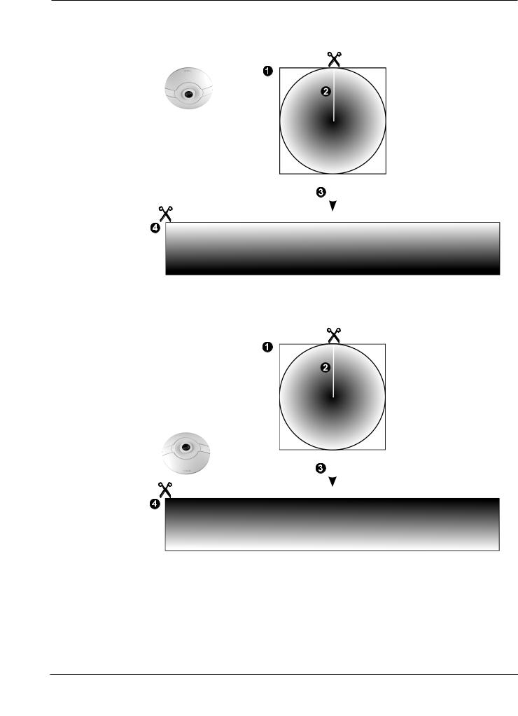
4.6.1360° panoramic camera - flooror ceiling mounted
The following figure illustrates the dewarping of a 360° camera which is flooror ceiling mounted.
2020.08 | V 1 | Operator Client |
Operation manual |
Bosch Security Systems B.V. |
BVMS |
|
|
Concepts | en 23 |
|||
|
|
|
|
|
|
|
|
|
|
|
|
|
|
|
|
|
|
|
|
|
|
|
|
|
|
|
|
|
|
|
|
|
|
|
|
|
|
|
|
|
|
|
|
|
|
|
|
|
|
|
|
|
|
|
|
|
|
|
|
|
|
|
|
|
|
|
|
|
|
|
|
|
|
|
|
|
|
|
|
|
|
|
|
|
|
|
|
|
|
|
|
|
|
|
|
|
|
|
|
|
|
|
|
|
|
|
|
|
|
|
|
|
|
|
|
|
|
|
1 |
Full circle image |
3 |
Dewarping |
|
|
|
|
2 |
Snipping line (operator can change its |
4 |
Panorama view |
|
position when not zoomed in) |
|
|
|
|
|
|
Bosch Security Systems B.V. |
Operation manual |
2020.08 | V 1 | Operator Client |

24 en | Concepts |
BVMS |
|
|
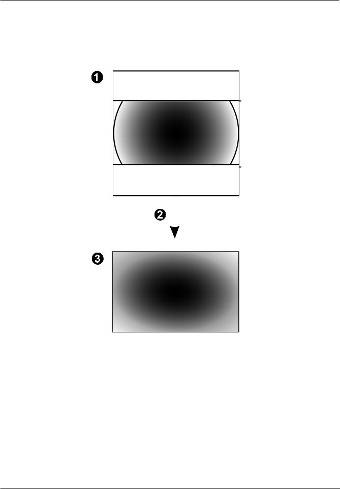
4.6.2180° panoramic camera - flooror ceiling mounted
The following figure illustrates the dewarping of a 180° camera which is flooror ceiling
mounted. |
|
|
|
|
|
|
|
|
|
|
|
|
|
|
|
|
|
|
|
|
|
|
|
|
|
|
|
|
|
|
|
|
|
|
|
|
|
|
|
|
|
|
|
|
|
|
|
|
|
|
|
|
|
|
|
|
|
|
|
|
|
|
|
|
|
|
|
|
|
|
|
|
1 |
Full circle image |
|
3 |
Dewarping |
|||
|
|
|
|
|
|
|
|
2 |
Snipping line (operator can change its |
|
4 |
Panorama view |
|||
|
position when not zoomed in) |
|
|
|
|
|
|
|
|
|
|
|
|
|
|
2020.08 | V 1 | Operator Client |
Operation manual |
Bosch Security Systems B.V. |

BVMS |
Concepts | en 25 |
|
|
4.6.3360° panoramic camera - wall mounted
The following figure illustrates the dewarping of a 360° camera which is wall mounted.
1 |
Full circle image |
3 |
Panorama view |
|
|
|
|
2 |
Dewarping |
|
|
|
|
|
|
Bosch Security Systems B.V. |
Operation manual |
2020.08 | V 1 | Operator Client |
26 en | Concepts |
BVMS |
|
|
4.6.4180° panoramic camera - wall mounted
The following figure illustrates the dewarping of a 180° camera which is wall mounted.
|
|
|
|
|
|
|
|
|
|
|
|
|
|
|
|
|
|
|
|
|
|
|
|
|
|
|
|
|
|
|
|
|
|
|
|
|
|
|
|
|
|
|
|
|
|
|
|
|
|
|
|
|
|
|
|
|
|
|
|
|
|
|
|
|
|
|
|
|
|
|
|
|
|
|
|
|
|
|
|
|
|
|
|
|
|
|
|
1 |
Full circle image |
|
3 |
Panorama view |
|
||
|
|
|
|
|
|
|
|
2 |
Dewarping |
|
|
|
|
|
|
|
|
|
|
|
|
|
|
2020.08 | V 1 | Operator Client |
Operation manual |
Bosch Security Systems B.V. |
BVMS |
Concepts | en 27 |
|
|
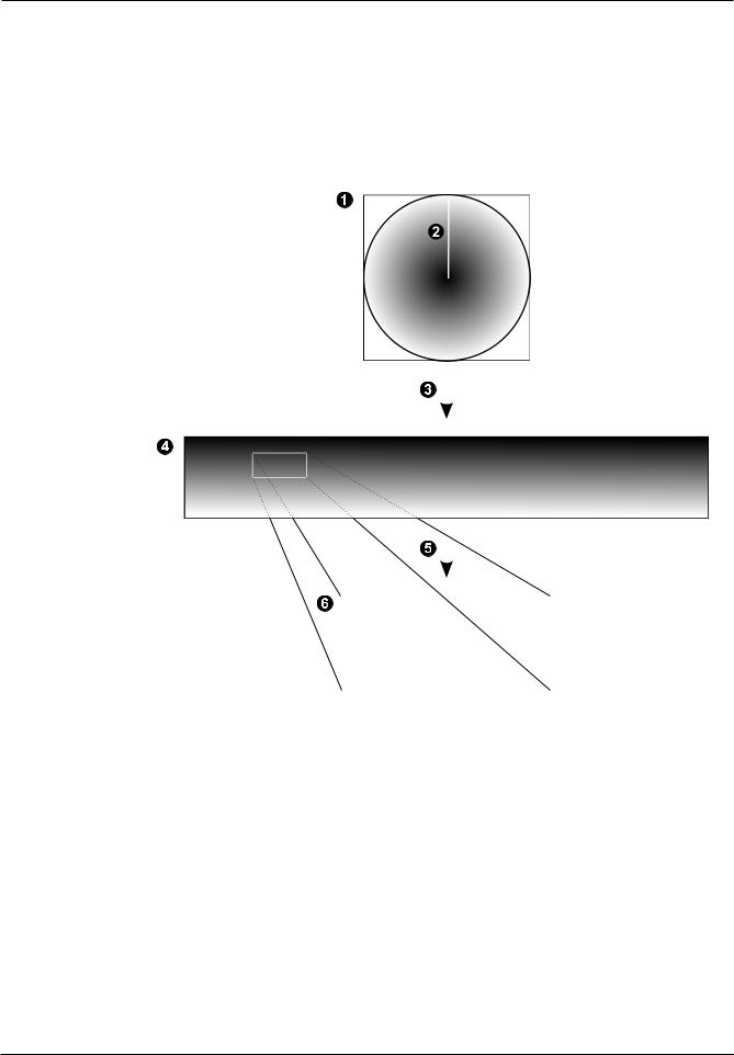
4.6.5Cropped view on a panoramic camera
The following example figure illustrates the cropping of a 360° camera which is flooror ceiling mounted.
The rectilinear section used for cropping is fixed. You can change the section in the cropped Image pane using the available PTZ controls.
|
|
|
|
|
|
|
|
|
|
|
|
|
|
|
|
|
|
|
|
|
|
|
|
|
|
|
|
|
|
|
|
|
|
|
|
|
|
|
|
|
|
|
|
|
|
|
|
|
|
|
|
|
|
|
|
|
|
|
|
|
|
|
|
|
|
|
|
|
|
|
|
|
|
|
|
|
|
|
|
|
|
|
|
|
|
|
|
|
|
|
|
|
|
|
|
|
|
|
|
|
|
|
|
|
|
|
|
|
|
|
|
|
|
|
|
|
|
|
|
|
|
|
|
|
|
|
|
|
|
|
|
1 |
Full circle image |
4 |
Panorama view |
|||||||
|
|
|
|
|
|
|
|
|
||
2 |
Snipping line (operator can change its |
5 |
Cropping |
|||||||
|
position when not zoomed in) |
|
|
|
|
|
|
|||
3 |
Dewarping |
6 |
Cropped Image pane |
|||||||
|
|
|
|
|
|
|
|
|
|
|
Bosch Security Systems B.V. |
Operation manual |
2020.08 | V 1 | Operator Client |

28 en | Concepts |
BVMS |
|
|
4.7SSH Tunneling
BVMS provides remote connectivity utilizing Secure Shell (SSH) tunneling.
SSH tunneling constructs an encrypted tunnel established by an SSH protocol/socket connection. This encrypted tunnel can provide transport to both encrypted and un-encrypted traffic. The Bosch SSH implementation also utilizes Omni-Path protocol, which is a high performance low latency communications protocol developed by Intel.
Technical aspects and restrictions
–SSH tunneling utilizes port 5322. This port cannot be modified.
–The SSH Service must be installed on the same server as the BVMS Management Server.
–(Enterprise) user accounts must have a configured password. (Enterprise) user accounts without a password cannot log on utilizing a SSH connection.
–Local storage cameras do not support SSH connection.
–Configuration Client cannot connect remotely via SSH. Configuration Client connection must be done via port mapping.
–Operator Client checks connection with SSH service every 15 seconds. If the connection is interrupted, Operator Client retests the connection every minute.
Port mapping
4Configure one port forwarding for the BVMS Management Server to utilize port 5322 for both internal and external connections.
This is the only port mapping entry that you need to make for the entire system. BVMS port mapping is not required.
Encrypted communication
After the connection is established via a SSH tunnel, all communications between the BVMS Management Server and a remote client are encrypted.
2020.08 | V 1 | Operator Client |
Operation manual |
Bosch Security Systems B.V. |

BVMS Getting started | en 29
5 Getting started
This chapter provides information on how to get started with BVMS.
5.1Starting Operator Client
Note:
–Before using the system, activate the licenses that you have ordered. The Configuration Manual or the Configuration Client Online Help describe how to activate the licenses.
–To be sure that your BVMS uses the language that you need, please configure this language in your Configuration Client. See the Online Help for details.
If a newer version of BVMS is running on the Management Server, this version is installed automatically by no-touch deployment when you log on.
To start the Operator Client:
1.From the Start menu, select Programs > BVMS > Operator Client. The dialog box for logging on is displayed.
2.Type your user name in the User Name: field.
3.Type your password in the Password: field.
Note: When you start the application for the first time, type Admin as user name, no password required.
To access multiple Management Server computers simultaneously, type the user name of a member of an Enterprise User Group.
4.In the Connection: list, select the IP address or the DNS name of the Management Server or Enterprise Management Server.
Note: If you use a SSH connection, select <New...> and enter the address in the following format: ssh://IP or servername:5322.
To use a SSH connection user accounts must have a configured password (see SSH Tunneling, page 28).
5.Click Ok.
If dual authorization has been configured for your user group, the next logon dialog is displayed.
A user of the configured second user group enters the required information. The application starts.
If dual authorization is optional, just click Ok again on the second logon dialog box. But you then only have the user rights of your user group and not the potentially extended user rights of your dual authorization group.
To start the Operator Client using Single Sign-on:
Notice!
To start the Operator Client using Single Sign-on, the user has to be associated to a LDAP user group that is configured in the Configuration Client.
SSH connection and dual authorization are not supported if a user connects to the Operator Client using Single Sign-on.
1.From the Start menu, select Programs > BVMS > Operator Client. The dialog box for logging on is displayed.
2.Select the Use Windows session credentials check box.
3.In the Connection: list, select the IP address or the DNS name of the Management Server or Enterprise Management Server.
4.Click Ok.
Bosch Security Systems B.V. |
Operation manual |
2020.08 | V 1 | Operator Client |

30 en | Getting started |
BVMS |
|
|
To quit Operator Client:
1.On the System menu, click Exit. The application quits.
If you logged on to Operator Client as a user who is not authorized to quit the application, the Enter Logoff Password dialog box is displayed.
2.Ask a user with corresponding user rights to enter his user name and password to confirm the process.
Refer to
– SSH Tunneling, page 28
5.2Accepting a new configuration
When the system administrator activates a new configuration from within Configuration Client, each Operator Client is either immediately restarted automatically or the user of a workstation is informed about the new configuration and can accept it later. The system administrator configures which of these 2 cases occurs.
If the system administrator activated a new configuration without forcing each Operator Client workstation to accept the new configuration, a dialog box is displayed on all Operator Client workstations. The users can refuse or accept the new configuration. The dialog box is closed after a few seconds without user interaction. In this case the new configuration is refused. If a device (for example a camera) is removed from the system in the new configuration, some functions of this device are not available if you have refused the new configuration.
If you change the password for a user or delete a user while this user is logged on, this user can still continue working with Operator Client after password change or deletion. If after password change or deletion the connection to Management Server is interrupted (for example after activating the configuration), the user cannot automatically reconnect to the Management Server again without logoff/logon at Operator Client.
To accept a new configuration:
4Log off and then log on again.
The new configuration is used now.
5.3Accessing the system
You access a system performing the following steps:
1.Perform one of the following steps to select the network address of the desired system:
–Click a preselected list entry.
–Enter a network address manually.
–Select a network address using Server Lookup.
2.Log on to the desired system:
–Single server system
–Enterprise System
5.4Using Server Lookup
–The BVMS Server Lookup feature allows Operators to connect to a BVMS Management Server out of a provided list of servers.
–A single user of Configuration Client or Operator Client can connect to multiple system access points sequentially.
–System access points can be Management Server or Enterprise Management Server.
–Server Lookup uses dedicated Management Server to host the Server List.
2020.08 | V 1 | Operator Client |
Operation manual |
Bosch Security Systems B.V. |
Loading...