


Typ1 osa / CC 220
Diagnosis
Operation, Application
Version 101

Typ1 osa / CC 220
Diagnosis
Operation, Application
1070 073 306-101 (91.10) GB
(V25)
E 1991
by Robert Bosch GmbH,
All rights reserved, including applications for protective rights. Reproduction or handing over to third parties are subject to our written permission.
Discretionary charge 10.– DM

Flexible Automation
Contents |
CC 220 / 320 |
|
Diagnosis |
||
|
Contents
1. General . . . . . . . . . . . . . . . . . . . . . . . . . . . . . . . . . . . . . . . . . . . . . . . . . . . . . . 1 – 1 2. Safety instructions . . . . . . . . . . . . . . . . . . . . . . . . . . . . . . . . . . . . . . . . . . . − 1 – 1 3. Calling the diagnostic programs . . . . . . . . . . . . . . . . . . . . . . . . . . . . . . . . . 1 – 2
4.Description of the diagnostic programs
D1 |
Logbook . . . . . . . . . . . . . . . . . . . . . . . . . . . . . . . . . . . . . . |
− D1 – 1 |
|
D5 |
Internal reference point offset . . . . . . . . . . . . . . . . . . . . |
. . . D5 |
– 1 |
D6 |
Interface data . . . . . . . . . . . . . . . . . . . . . . . . . . . . . . . . . . |
. . . D6 |
– 1 |
D7 |
Communication store display . . . . . . . . . . . . . . . . . . . . . |
. . D7 |
– 1 |
D9 |
EEPROM management . . . . . . . . . . . . . . . . . . . . . . . . . |
− D9 – 1 |
|
D21 |
Logic analyzer . . . . . . . . . . . . . . . . . . . . . . . . . . . . . . . . |
− D21 – 1 |
|
D22 |
Axis oscilloscope . . . . . . . . . . . . . . . . . . . . . . . . . . . . . . |
− D22 – 1 |
|
D23 |
Contour display . . . . . . . . . . . . . . . . . . . . . . . . . . . . . . . |
− D23 – 1 |
|
D24 |
Axis optimization . . . . . . . . . . . . . . . . . . . . . . . . . . . . . . . . |
. D24 |
– 1 |
D25 |
Lead screw error compensation . . . . . . . . . . . . . . . . . |
− D25 – 1 |
|
D26 |
CNC remote diagnosis (information) . . . . . . . . . . . . . . . |
. D26 |
– 1 |
D27 |
Putting into operation for circular compensation . . . |
‘ D27 – 1 |
|
D28 |
Tapping . . . . . . . . . . . . . . . . . . . . . . . . . . . . . . . . . . . . . . |
‘ D28 – 1 |
|
Notes: Diagnostic programs which are not available in the CC 200/300 are identified by an ‘ in front of the page number.
If a diagnostic program contains new or modified functions – compared with the controls of the Type CC 200/300 –, this is indicated by a − in front of the page number.
The following diagnostic programs are intended exclusively for BOSCH service personnel and are not described in this manual:
D2 Reloading the operating program
D3 Cancelling all memory
Separate manuals are available for the diagnostic programs D4 and D26:
D4 |
Machine parameter program |
CC 220 |
M/T: |
P. No.: 4201 |
|
|
CC 320 |
M: |
P. No.: 4180 |
D26 |
CNC remote diagnosis |
|
|
P. No.: 4184 |
The diagnostic programs D8 Change language
D10 Library management
implemented in the CC 220/320 are no longer present as special diagnostic programs in controls of the type CC 220/320, but can now be called directly by way of softkey. Please refer to the appropriate operating manual for operating instructions.
C – 1

Flexible Automation
Contents |
CC 220 / 320 |
|
Diagnosis |
||
|
C – 2

Flexible Automation
General
CC 220 / 320
Diagnosis
1.General
This manual refers to the software version V25 for the controls CC 220/320.
The diagnostic programs D21 to D28 are options which are subject to charge.
2.Safety instructions
MOVE
MP
SERVO
DATA
Diagnostic programs permit critical changes to be made in the interaction of CNC, machine and drives right up to complete deletion of the CNC memory.
If they are used by insufficiently trained or untrained personnel, this may thus result in serious damage to the machine and drives, loss of software or even injury!
For this reason, diagnostic programs must be started and operated only by correspondingly trained expert personnel.
In this context, please note our extensive range of training courses. You will find an overview of the available seminars on the inner cover of this manual. Our training center will gladly provide you with further information.
In some diagnostic programs, axes have to be traversed in order to optimize CNC servo loops and drives.
For this reason, make sure that no one enters the machine’s danger area during execution of such diagnostic programs.
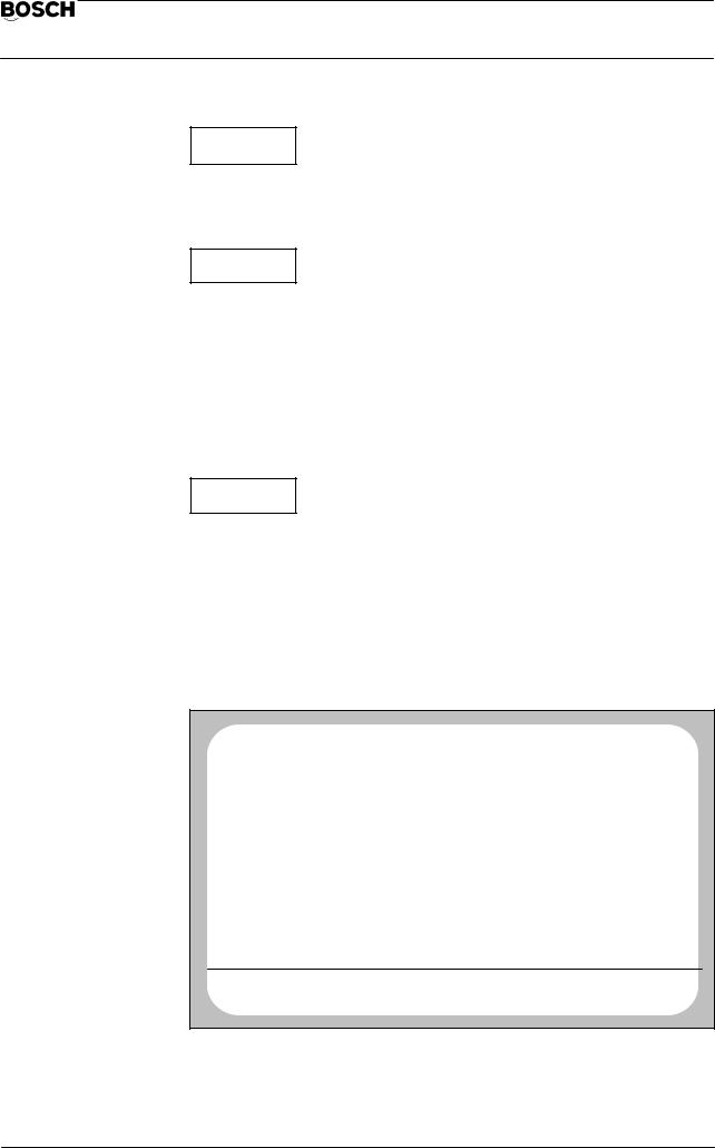
The following symbols are used in this manual in order to point out certain things which are relevant to safety:
Axis movement possible!
For this reason, make sure that there are no persons or objects in the machine’s danger area.
Make sure that no collisions are possible in the axis traversing range.
Machine parameter record is modified! This is followed by a CNC restart. The modified machine parameters are active after this.
Is there a backup of the original machine parameters?
BOSCH will not be liable for damaging resulting from incorrectly calculated, programmed or optimized machine parameters or non–observance of limit data!
Active axis processor data is modified!
This effects the axis response.
Data loss possible!
Data in the user RAM (part programs, tables etc.) may possibly be deleted or overwritten.
Do you possess a backup of this data?
3.Calling the diagnostic programs
1 – 1

Flexible Automation
General
CC 220 / 320
Diagnosis
The following monitor display appears after selection of group operating mode
(DIAGNOSTIC):
No |
CP0 |
NC0 |
|
|
|
|
|
DIAGNOSTIC |
PROGRAM |
ACT |
STOP |
|
|
|
|
|
12. 5 16:53 |
|
|
|
|
|
|
|||
ERROR |
|
CONDITION ON |
|
|
STATUS |
|||
|
|
G |
|
G |
1 |
G |
71 |
DRIVE ON |
|
|
90 |
G |
66 |
G 140 |
|
||
|
|
G |
94 |
G |
40 |
G |
7 |
|
|
|
G 14 |
G |
8 |
G |
27 |
|
|
|
|
G |
15 |
G |
29 |
G |
79 |
|
|
|
G |
80 |
G 130 |
G |
53 |
|
|
|
|
G 153 |
G 253 |
G |
67 |
|
||
|
|
G 39 |
G 62 |
G 97 |
|
|||
|
|
G |
65 |
G |
68 |
G |
99 |
|
|
|
G 146 |
G 115 |
G 167 |
|
|||
|
|
G 994 |
|
|
|
|
|
|
|
AT LAST PROGR. |
|
|
|
|
|
|
|
|
||
|
F |
0.0 |
|
|
T 0 |
|
|
M 0 |
|
|
|
|
|
|
|
|
|
|
|
|
|
|
|
|
|
|
|
|
|
|
|
|
|
|
|
|
DIAGNOSTIC |
|
DIAGNOSTIC |
|
RESET |
SERVICE |
|
||||
|
|
CONTROL |
|
MACHINE |
|
FUNCTION |
FUNCTION |
|
|||
|
|
|
|
|
|
|
|
|
|
|
|
The control displays all available diagnostic programs after operation of the softkey SERVICE FUNCTION (possibly only after input of a code number; refer to the section ”Notes”):
|
|
No |
CP0 |
NC0 |
|
DIAGNOSTIC |
|
|
PROGRAM |
ACT |
WAIT |
|
14.10 8:28 |
|
|
NUMBER |
|
PROGRAM NAME |
LENGTH |
ACCESS |
D |
1 |
LOGBOOK MONITOR |
|
E |
||
D |
2 |
RELOAD OPERATING PROGRAM |
|
E |
||
D |
3 |
CANCEL ALL MEMORY |
|
E |
||
D |
4 |
MACHINE PARAMETER PROGRAM |
|
E |
||
D |
5 |
INTERNAL REF. POINT OFFSET |
|
E |
||
D |
6 |
INTERFACE DATA |
|
E |
||
D |
7 |
COMMUNICATION STORE DISPLAY |
|
E |
||
D |
9 |
MANAGE EEPROM |
|
E |
||
D |
21 |
LOGIC–ANALYZER |
|
E |
||
D |
22 |
AXIS OSCILLOSCOPE |
|
E |
||
D |
23 |
CONTOUR DISPLAY |
|
E |
||
D |
24 |
AXIS OPTIMIZATION |
|
E |
||
D |
25 |
LEAD SCREW ERROR COMPENSATION |
|
E |
||
D |
27 |
PUTTING INTO OPERATION FOR CIRCULAR COMPENSATIONE |
||||
MEMORY USED BY DIAG.: |
44384 |
OTHERS: |
2658 |
|
MEMORY AVAILABLE: |
2574398 |
|
|
|
SERVICE FUNCTION |
|
|
|
|
|
|
|
|
|
|
DATA IN |
DATA OUT |
START |
DELETE |
|
|
|
|
|
The system asks for the number of the desired program when the softkey START is pressed. Input of the program number is acknowledged with the ENTER key. The CNC then starts the corresponding diagnostic program.
1 – 2

Flexible Automation
General
CC 220 / 320
Diagnosis
Notes:
‘If the softkey RESET FUNCTION and then softkey CLEAR ALL LOGIC are pressed in group operating mode DIAGNOSTIC, it is possible to enter the softkey level SERVICE FUNCTION only by input of a code number as from this point in time.
When a correct code number has been entered, the softkey level SERVICE FUNCTION is accessible without input of the code number until renewed operation of the softkey sequence DIAGNOSTIC, RESET FUNCTION, CLEAR ALL LOGIC.
‘Some diagnostic programs create files with the group identifier ”L” or ”D” for recording data. This reduces the memory space which is available for part programs.
‘Data recordings can be repeated any number of times within diagnostic programs, since the previous recording is overwritten by each new recording. All other operating modes of the control can be used during recording of data by a diagnostic program.
Exception: CONTROL RESET and selection of a different diagnostic program cancel the currently active diagnostic program (except for D21).
1 – 3

Flexible Automation
General
CC 220 / 320
Diagnosis
1 – 4

Flexible Automation
D1 Logbook |
CC 220 / 320 |
|
Diagnosis |
||
|
4.Description of the diagnostic programs
D1 – Logbook
General
The diagnostic program D1 is used for management of one or more ”logbooks”. A logbook is a file with the identifier ”D” which contains various data for reconstruction of operating sequences, error messages or warnings etc. This file is divided into 5 ring memories which store warnings, errors, system errors, other messages and operating steps in the order of their occurrence.
Activating/deactivating a logbook
There are two possibilities for activation of a logbook:
‘Input of a logbook file number in machine parameter P 9914. Then ACTIVATE the machine parameters. The logbook is automatically initialized with the specified file number after control start–up and is active as from this point in time. The ring memories are created with the following sizes: R1 to R4: 512 bytes, R5: 0 byte.
‘Operation of softkey INIT in diagnostic program D1.
An already active logbook can be deactivated in diagnostic program D1 by pressing softkey INIT, input of ”0” and acknowledgement with the ENTER key or by selection of a different logbook (also refer to softkey LOGBOOK SELECTION). A logbook cannot be activated again once it has been deactivated. Only deactivated logbooks can be deleted.
User interface/softkey assignments
The following display appears if no logbook is yet active when D1 is selected:
No |
CP0 |
NC0 |
DIAGNOSTIC |
PROGRAM |
ACT |
STOP |
12. 5 16:59 |
LOGBOOK NOT INITIALIZED!
DISPLAY |
|
INIT |
LOGBOOK |
LOGBOOK |
RING STORE |
|
SELECTION |
PUNCHOUT |
|
|
|
|||
|
|
|
|
|
D1 – 5
Flexible Automation
D1 Logbook |
CC 220 / 320 |
|
Diagnosis |
||
|
The following monitor display is shown if a logbook is already active:
|
|
No |
CP0 |
NC0 |
|
|
|
DIAGNOSTIC |
|||
|
|
PROGRAM |
ACT |
STOP |
|
|
|
12. 5 16:59 |
|
|
|
|
|
LOGBOOK |
|
D 11000 ACTIVE |
|
|
|
||||
|
|
|
|
|
|
|
|
|
|
|
|
|
RING STORE FOR WARNING |
|
|
|
|
SIZE = |
100 BYTES |
||||
|
RING STORE 2 FOR ERRORS |
|
|
|
|
SIZE = |
100 BYTES |
||||
|
RING STORE 3 FOR SYSTEM ERRORS |
|
|
SIZE = |
100 BYTES |
||||||
|
RING STORE 4 FOR OTHER MESSAGES |
|
|
SIZE = |
100 BYTES |
||||||
|
RING STORE 5 FOR OPERATING STEPS |
|
|
SIZE = |
100 BYTES |
||||||
|
TEST POINT 1 ADDRESS 0000064 |
|
|
|
|
|
|
||||
|
TEST POINT 2 ADDRESS 00000000 |
|
|
|
|
|
|
||||
|
TOTAL LOGBOOK SIZE: |
|
|
|
605 BYTES |
|
|
|
|||
|
|
|
|
|
|
|
|
|
|
|
|
|
|
|
|
|
|
|
|
|
|
|
|
|
|
DISPLAY |
|
|
|
INIT |
|
LOGBOOK |
LOGBOOK |
||
|
|
RING STORE |
|
|
|
|
SELECTION |
PUNCHOUT |
|||
|
|
|
|
|
|
|
|||||
|
|
|
|
|
|
|
|
|
|
|
|
INIT
Initialization of a logbook (creation of a new logbook file).
When the softkey INIT is pressed, the CNC expects input of a logbook file number (value range 0.3000–999999999).
Input of ”0” deactivates a currently active logbook (”active” means that recordings take place in this logbook). A logbook cannot be activated again once it has been deactivated. Only deactivated logbooks can be deleted.
Two test points are interrogated after input of the file number. However, these are of importance only for service purposes. Skip test point input by pressing the ENTER key twice.
The system then asks for the memory size for the individual ring stores. Reservation of approx. 500 bytes per ring store will already permit a sensible recording to be made.
After this, the logbook is initialized and automatically activated. Any events which occur are recorded from this point in time onwards.
The number of logbooks which can be created is limited by the available memory space. Only one logbook can be active at any time.
In order to use the file number of a deactivated logbook again for an active logbook, it is first necessary to delete the deactivated logbook in the softkey level SERVICE FUNCTION and to then create a logbook again in D1 under softkey INIT.
LOGBOOK
SELECTION
Selection of any existing deactivated logbooks for display on the monitor.
D1 – 6

Flexible Automation
D1 Logbook |
CC 220 / 320 |
|
Diagnosis |
||
|
LOGBOOK
PUNCHOUT
The currently displayed logbook is output on an external data medium. The current setting in group operating mode DATA I/O, softkey DATA OUT, determines via which interface output takes place. A change in operating mode aborts active output. Output via the DNC interface is not possible.
DISPLAY
RING STORE
This softkey results in display of the contents of the individual ring stores. The store contents are displayed in plain text with data, time and message.
Example: Ring store 1 (warnings):
|
No |
CP0 |
|
NC0 |
|
|
DIAGNOSTIC |
|
|
PROGRAM |
ACT |
|
STOP |
|
|
|
|
|
|
|
|
|
||||
LOG |
11 23.05 |
09:31 |
WARNING: DATA PROTECTED |
|||||
|
KEYING: |
DATA SK1+ SK1− |
1 |
0 |
ENTR |
|||
|
TEST POINT: |
1=00000000 |
2=00000000 |
|
MODE: DATA |
|||
LOG |
7 16.05 |
11:34 |
WARNING: AXIS MOVING |
|||||
|
KEYING: |
SK5+ |
SK5− |
DIAG |
SK3+ |
SK3− SK3+ |
||
|
TEST POINT: |
1=00000000 |
2=00000000 |
MODE: DIAGNOSTIC |
||||
DISPLAY END
PAGE |
PAGE |
LAST |
SOFTKEY |
|
FORWARDS |
BACK |
KEY |
MASK |
|
Example: Ring store 5 (operating steps):
|
No |
|
CP0 |
NC0 |
|
|
|
|
DIAGNOSTIC |
||
|
PROGRAM |
ACT |
STOP |
|
|
|
12. 5 17: 5 |
|
|||
SK4− |
SK4+ |
|
|
RESET |
SK3+ |
ENTR |
1 |
SK4− |
SK4+ |
||
|
|
SK3− |
SK3+ |
DIAG |
ERET |
||||||
ERET |
ERET |
ERET |
ERET |
ENTR |
6 |
5 |
2 |
7 |
2 |
|
|
SK4− |
SK4+ |
SK4− |
SK4+ |
|
|
RESET |
SK3+ |
SK3− |
SK3+ |
||
DIAG |
SK4− |
SK4+ |
ENTR |
6 |
5 |
2 |
7 |
2 |
SK4− |
||
SK4+ |
2 |
5 |
2 |
SK4− |
SK4+ |
DIAG |
SK3− |
SK3+ |
SK3− |
||
SK3+ |
SK4− |
SK4+ |
SK4− |
SK4+ |
DIAG |
DATA |
RESET |
SK5+ |
SK4− |
||
SK4+ |
SK3− |
SK3+ |
DIAG |
ERET |
SK5− |
SK5+ |
ENTR |
0 |
1 |
|
|
SK5− |
SK5+ |
ENTR |
0 |
2 |
SK1− |
SK1+ |
SK1− |
SK1+ |
SK5− |
||
SK5+ |
ERET |
SK4− |
SK4+ |
SK3− |
SK3+ |
SK5− |
SK5+ |
ENTR |
0 |
|
|
2 |
SK1− |
SK1+ |
SK3− |
SK3+ |
SK5− |
SK5+ |
SK1− |
SK1+ |
SK3− |
||
SK3+ |
DATA |
SK2− |
SK2+ |
SK1− |
SK1+ |
SK1− |
SK1+ |
SK1− |
SK1+ |
||
ENTR |
5 |
SK1− |
SK1+ |
ERET |
SK2− |
SK2+ |
SK1− |
SK1+ |
SK2− |
||
SK2+ |
SK1− |
SK1+ |
ENTR |
1 |
SK1− |
SK1+ |
ENTR |
3 |
3 |
|
|
SK4− |
SK4+ |
ENTR |
2 |
SK4− |
SK4+ |
ERET |
SK4− |
SK4+ |
SK4− |
||
PAGE PAGE
FORWARDS BACK
The last–pressed key is shown at the top left in the uppermost data line of the monitor (”ENTR” here in the example).
D1 – 7

Flexible Automation
D1 Logbook |
CC 220 / 320 |
|
Diagnosis |
||
|
The following abbreviations are used for display of the keys:
ABAR, MDI, MASC, DATA, DIAG, KORR |
Group operating modes |
CUP+, CDN+, CRI+, CLE+ |
Cursor keys pressed |
CUP–, CDN–, CRI–, CLE– |
Cursor keys released |
LPE+ |
Magnifier pressed |
LPE– |
Magnifier released |
SK1+, SK2+, SK3+, SK4+, SK5+ |
Softkey pressed |
SK1–, SK2–, SK3–, SK4–, SK5– |
Softkey released |
ERET |
Level return |
DEL |
Delete key |
ENTR |
Enter key |
1 ... 0 |
Numeric keys |
: * – + = |
Arithmetic operation keys |
+/– |
Sign change |
. |
Decimal point |
RESET |
Stands for Control Reset, |
|
CAL = System error 1 |
|
NC reset, switching on/off, |
|
Logbook Init |
?? |
Unknown key code |
SOFTKEY
MASK
The softkey mask present at the time of the entry is displayed. If the key assignment is displayed by a number, this indicates variable softkey designations, such as occur, for example, for wool sub–tables.
D1 – 8

Flexible Automation
D5 Internal reference point offset |
CC 220 / 320 |
|
Diagnosis |
||
|
D5 – Internal reference point offset
The currently active axis offset values are displayed after selection of the program D5.
These may have been generated by G92 or by ZERO SET. Zero offsets by way of G54 – G59, G154 – G159, G254 – G259, G60 or G160 are not taken into account here.
|
|
No |
|
CP0 |
NC0 |
|
DIAGNOSTIC |
|||
|
|
PROGRAM |
|
ACT |
WAIT |
14.10 8:32 |
|
|
||
|
|
AXIS |
OFFSET VALUE |
|
|
|
|
|||
|
|
X |
767.766 |
MM |
|
|
|
|
||
|
|
Y |
− 715.692 |
MM |
|
|
|
|
||
|
|
Z |
124.423 |
MM |
|
|
|
|
||
|
|
|
|
|
|
|
|
|
|
|
|
|
|
|
|
|
|
|
|
|
|
|
|
|
|
|
|
|
|
|
|
|
|
|
|
|
|
|
|
|
|
|
|
D5 – 9

Flexible Automation
D5 Internal reference point offset |
CC 220 / 320 |
|
Diagnosis |
||
|
D5 – 10

Flexible Automation
D6 Interface data |
CC 220 / 320 |
|
Diagnosis |
||
|
D6 – Interface data
General
Data arriving at the standard interfaces can be displayed with D6. The data is not stored during this operation.
No check is made of the data (e.g. with respect to correct file header, program end, ECODE etc.). Reading–in is not subject to any time monitoring function. No message is issued if data transfer is faulty.
User interface/softkey assignments
The following functions are offered after program selection:
|
|
|
|
|
|
DEVICE |
STATUS |
DFS |
DFS–NO. |
START |
|
SELECT |
SEARCH |
SEARCH |
|||
|
|
DEVICE
SELECT
Selection of the data interface and definition of the connected peripheral device.
STATUS
The following softkey bar appears when STATUS is pressed:
|
|
|
|
|
SW |
|
HEX |
CHAR/HEX |
CHAR/SYMB |
CONTROL |
|
|||
|
|
|
|
SW
CONTROL
Activation/deactivation of the XON/XOFF protocol.
Softkey is shown inverted: software handshake active (Xon/Xoff).
Softkey is displayed normally: hardware handshake active (DTR/DSR).
HEX
Display of the incoming data in HEX format.
CHAR/HEX
Incoming data is displayed as ASCII characters. Exception: display of control characters occurs in HEX format.
CHAR/SYMB
Incoming data is shown as ASCII characters. Exception: control characters are displayed symbolically (e.g. <SP> = Space, <LF> = Line Feed).
D6 – 11
Flexible Automation
D6 Interface data |
CC 220 / 320 |
|
Diagnosis |
||
|
START
Start of the reading–in operation. This operation continues until the screen is full. Half of the screen is filled again in each case by repeated operation of this key.
DFS
SEARCH
Reading–in is started by pressing the softkeys DFS SEARCH and START and is then continued until a correct DFS identifier is found. After this, a maximum of 17 lines of the program/table are displayed. The rest of the incoming program/table data of this file is skipped after renewed operation of DFS SEARCH and then START. The control displays the first 17 lines of the program/table again only after the next DFS identifier has been found.
Note: ”DFS search” is active as long as the softkey is shown inverted. The function is executed only if the DFS identifier is correctly received.
DFS–NO.
SEARCH
The system asks for the file number for which a search is to be made after operation of this softkey. After input of this number and subsequent operation of the softkey START, reading–in takes place until the specified file number (DFS identifier) is found. The incoming data is displayed only after this has occurred.
Note: ”DFS search” is active as long as the softkey is displayed inverted. The function is executed only if the DFS identifier is received correctly.
Example: Display of read–in data in the format CHAR/HEX:
No |
CP0 |
NC0 |
DIAGNOSTIC |
PROGRAM |
ACT |
WAIT |
14.10 8:40 |
<13><12><00><00><00><00><00><00><00><00><00><00><00><00><00><00><00
<00><00><00><00><00><00><00><00><00><00><00><00><00><00><00><00><00
<00><00><00><00><00><00><00><00><00><00><00><00><00><00><00><00><00
<00><00><00><00><00><00><00><00><00><00><00><00><00><00><00><14><12
<00><00><00><00><00><00><00><00><00><00><00><00><00><00><00><00><00
<00><00><00><00><00><00><00><00><00><00><00><00><00><00><00><00><00
<00><00><00><00><00><00><00><00><00><00><00><00><00><00><00><00><00
<00><00><02><0D><0A>
<14><12>(DFS,P 55555,TEACH IN 18.08,RWED)< D><0A>
<14><12>1 A%=3:REM NUMBER OF AXES <0D><0A>
1A1$="X":REM AXIS ADDRESS<0D><0A>
1A2$="Y"<0D><0A>
1A3$="Z"<0D><0A>
1A4$="B"<0D><0A>
1A5$="B"<0D><0A>
1<14><12>B%=250:REM INTERFACE OUTPUT FOR SETTING MODE ACTIVATION <0D><0A>
INTERFACE DATA
DEVICE |
STATUS |
DFS− |
DFS−No. |
START |
|
SELECT. |
SEARCH |
SEARCH |
|||
|
|
||||
|
|
|
|
|
D6 – 12
Flexible Automation
D7 Communication store display |
CC 220 / 320 |
|
Diagnosis |
||
|
D7 – Communication store display
General
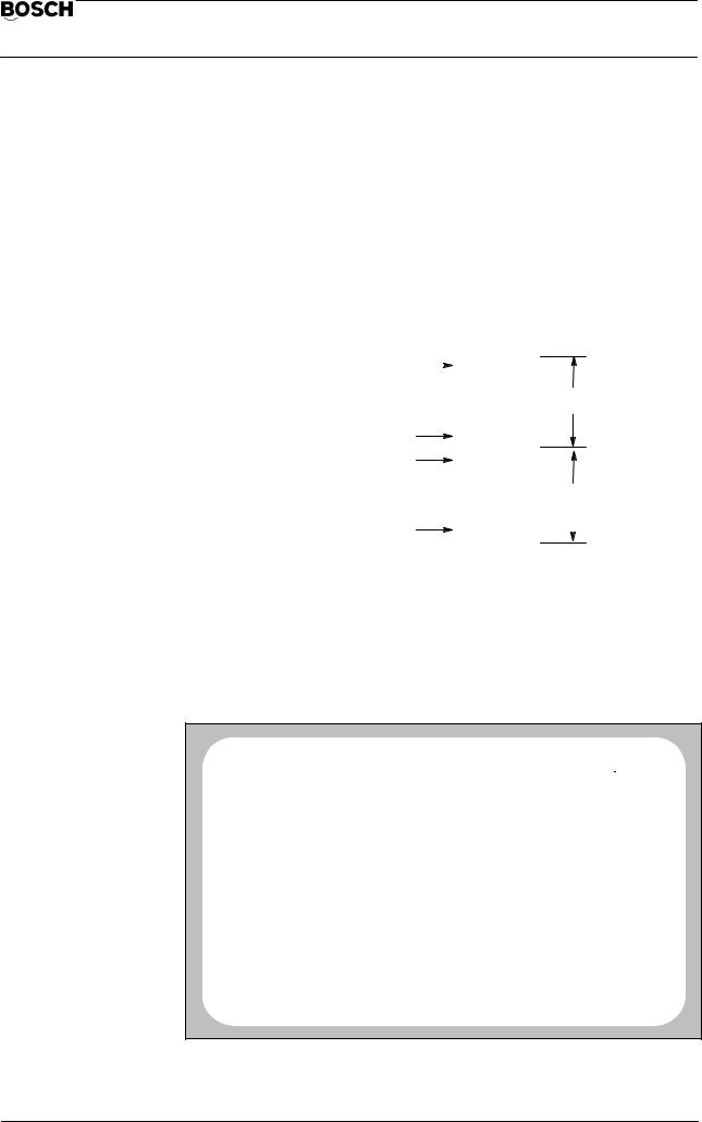
The content of the communication store from the point of view of the PLC can be displayed on the monitor of the CNC in hexadecimal format using the diagnostic program D7. D7 is offered only if word coupling exists between the CNC and PLC.
The communication store is a 128 KByte dual port RAM area on the NC–PLC–word module (WK3). Both the CNC and the PLC (PC 600) have read and write access to this area.
|
|
|
|
|
|
|
|
Start address Page 0 |
|
|
8000 H |
|
|
|
|
|
|
|
|
|
|||
|
|
|
. |
|
|
|
|
|
|
|
. |
|
|
|
|
|
|
|
. |
|
Page 0 |
||
|
|
|
. |
|
|||
|
|
|
. |
|
|
|
|
End address Page 0 |
FFFF H |
|
|
|
|
||
Start address Page 1 |
|
|
|
|
|
||
|
|
|
|
|
|||
8000 H |
|
|
|
|
|||
|
|
|
. |
|
|
|
|
|
|
|
. |
|
|
|
|
|
|
|
. |
|
Page 1 |
||
|
|
|
. |
|
|||
End address Page 1 |
. |
|
|
|
|
||
|
|
|
|
||||
FFFF H |
|
|
|
|
|||
|
|
|
|
|
|
|
|
|
|
|
|
|
|
|
|
User interface/softkey assignments
After D7 is started, the control always displays the communication store content from address C000 H to C07F H (address information as hexadecimal numbers from the point of view of the PLC):
|
|
No |
|
CP0 |
NC0 |
|
|
|
|
DIAGNOSTIC |
|
||
|
|
PROGRAM |
ACT |
WAIT |
|
|
|
|
17.10 14: 0 |
|
|||
|
|
|
|
|
|
|
|
|
|
|
|
|
|
|
|
C00 |
C01 |
C02 |
C03 |
C04 |
C05 |
C06 |
C07 |
|
|
|
|
|
0002 |
C400 |
0000 |
0000 |
BC34 |
0000 |
0000 |
0000 |
|
0 |
|
|
|
|
|
E752 |
F212 |
0000 |
0000 |
BC34 |
0000 |
0000 |
0000 |
|
1 |
|
|
|
|
E852 |
F24C |
0000 |
0000 |
0000 |
0000 |
0000 |
0000 |
|
2 |
|
|
|
|
E010 |
F04E |
0000 |
0000 |
0000 |
0000 |
0000 |
0000 |
|
3 |
|
|
|
|
E73E |
E95E |
0000 |
0000 |
0000 |
0000 |
0000 |
0000 |
|
4 |
|
|
|
|
E746 |
0000 |
0000 |
0000 |
0000 |
0000 |
0000 |
0000 |
|
5 |
|
|
|
|
E952 |
0000 |
0000 |
0000 |
0000 |
0000 |
0000 |
0000 |
|
6 |
|
|
|
|
F000 |
0000 |
0000 |
0000 |
0000 |
0000 |
0000 |
0000 |
|
7 |
|
|
|
|
EA26 |
0000 |
0000 |
0000 |
0000 |
0000 |
0000 |
0000 |
|
8 |
|
|
|
|
F006 |
0000 |
0000 |
0000 |
0000 |
0000 |
0000 |
0000 |
|
9 |
|
|
|
|
F026 |
0000 |
0000 |
0000 |
0000 |
0000 |
0000 |
0000 |
|
A |
|
|
|
|
F0BA |
0000 |
0000 |
0000 |
0000 |
0000 |
0000 |
0000 |
|
B |
|
|
|
|
E000 |
0000 |
0000 |
0000 |
0000 |
0000 |
0000 |
0000 |
|
C |
|
|
|
0000 |
0000 |
0000 |
0000 |
0000 |
0000 |
0000 |
0000 |
|
D |
|
|
|
|
|
F092 |
0000 |
0000 |
0000 |
0000 |
0000 |
0000 |
0000 |
|
E |
|
|
|
|
BB00 |
0000 |
0000 |
0000 |
0000 |
0000 |
0000 |
0000 |
|
F |
|
|
|
|
|
|
|
|
|
|
|
|
|
|
|
|
C000 |
COMMUNICATION STORE DISPLAY |
|
|
|
|
|
||
*000 |
|
0*00 |
00*0 |
*ADVANCE |
|
|
PAGE 0 |
|
|
BACKUP |
|
PAGE 1 |
|||||
|
|
|
|
|
||||
|
|
|
|
|
|
|
|
|
128 data words (256 bytes) can be displayed on one screen page. The data is displayed in a table form (8 columns of 16 lines each). It is possible to see the assign-
D7 – 13
Flexible Automation
D7 Communication store display |
CC 220 / 320 |
|
Diagnosis |
||
|
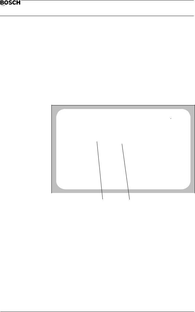
ment between the displayed data words and their addresses in the communication store by way of the inversely displayed bars above and on the right of the table.
The three most significant positions of an address (e.g. ”C02” of address ”C02F”) are shown in the top, highlighted bar, while the least significant position is shown in the bar on the right of the table (e.g. ”F” of the address ”C02F”).
The address of the top left data word is displayed in the prompt line (here in the example: ”C000 COMMUNICATION STORE DISPLAY”).
Example:
|
|
No |
|
CP0 |
NC0 |
|
|
|
|
DIAGNOSTIC |
|
|||
|
|
PROGRAM |
ACP |
WAIT |
|
|
|
|
17.10 14: 0 |
|
||||
|
|
|
|
|
|
|
|
|
|
|
|
|
|
|
|
|
C00 |
C01 |
C02 |
C03 |
C04 |
C05 |
C06 |
C07 |
|
|
|
|
|
|
0002 |
C400 |
0000 |
|
0000 |
BC34 |
0000 |
0000 |
0000 |
|
0 |
|
|
|
|
|
E752 |
F212 |
0000 |
|
0000 |
BC34 |
0000 |
0000 |
0000 |
|
1 |
|
|
|
|
E852 |
F24C |
0000 |
|
0000 |
0000 |
0000 |
0000 |
0000 |
|
2 |
|
|
|
|
E010 |
F04E |
0000 |
|
0000 |
0000 |
0000 |
0000 |
0000 |
|
3 |
|
|
|
|
E73E |
E95E |
0000 |
|
0000 |
0000 |
0000 |
0000 |
0000 |
|
4 |
|
|
|
|
E746 |
0000 |
0000 |
|
0000 |
0000 |
0000 |
0000 |
0000 |
|
5 |
|
|
|
|
|
|
|
|
|
||||||||
|
|
E952 |
0000 |
0000 |
|
0000 |
0000 |
0000 |
0000 |
0000 |
|
6 |
|
|
|
|
F000 |
0000 |
0000 |
|
0000 |
0000 |
0000 |
0000 |
0000 |
|
7 |
|
|
|
|
EA26 |
0000 |
0000 |
|
0000 |
0000 |
0000 |
0000 |
0000 |
|
8 |
|
|
|
|
F006 |
0000 |
0000 |
|
0000 |
0000 |
0000 |
0000 |
0000 |
|
9 |
|
|
|
|
F026 |
0000 |
0000 |
|
0000 |
0000 |
0000 |
0000 |
0000 |
|
A |
|
|
|
|
F0BA |
0000 |
0000 |
|
0000 |
0000 |
0000 |
0000 |
0000 |
|
B |
|
|
|
|
E000 |
0000 |
0000 |
|
0000 |
0000 |
0000 |
0000 |
0000 |
|
C |
|
|
|
0000 |
0000 |
0000 |
|
0000 |
0000 |
0000 |
0000 |
0000 |
|
D |
|
|
|
|
|
F092 |
0000 |
0000 |
|
0000 |
0000 |
0000 |
0000 |
0000 |
|
E |
|
|
|
|
BB00 |
0000 |
0000 |
|
0000 |
0000 |
0000 |
0000 |
0000 |
|
F |
|
|
|
|
|
|
|
|
|
|
|
|
|
|
|
|
|
|
C000 |
COMMUNICATION STORE DISPLAY |
|
|
|
|
|
|
|||
*000 |
|
0*00 |
|
00*0 |
*ADVANCE |
|
|
PAGE 0 |
|
||
|
|
BACKUP |
|
PAGE 1 |
|||||||
|
|
|
|
|
|
|
|||||
|
|
|
|
|
|
|
|
|
|
|
|
|
|
|
Address C025 H |
Address C046 H |
|
|
|
|
|||
Search for an arbitrary address
Select the required memory area by means of the softkey PAGE 0/PAGE1. The currently displayed memory area is shown inverted on the softkey.
The individual digits of the address displayed in the prompt line can be incremented or decremented by means of the three softkeys *000,0*00 and 00*0. The asterisk on the softkey indicates the position which is changed.
The least significant address need not be specified, since all 16 possible addresses are displayed underneath each other in one column.
It is possible to switch between incrementation and decrementation of the corresponding position by means of the softkey ADVANCE/BACKUP. The active condition is shown inverted.
D7 – 14

Flexible Automation
D7 Communication store display |
CC 220 / 320 |
|
Diagnosis |
||
|
Example:
You are on Page 0. The prompt line shows the address C000 H. You are looking for the content of the address D123 H on Page 0.
Switch to ”Increment” (the field ADVANCE on the softkey ADVANCE/BACKUP is then shown inverted).
Press the softkey *000 once. Press the softkey 0*00 once. Press the softkey 00*0 twice.
The 4th data value (from the top) in the left column now shows the content of address D123 H.
D7 – 15
Flexible Automation
D7 Communication store display |
CC 220 / 320 |
|
Diagnosis |
||
|
D7 – 16

Flexible Automation
D9 EEPROM management |
CC 220 / 320 |
|
Diagnosis |
||
|
D9 – EEPROM management
General
The MEM5 memory module (or CP/MEM4 in the case of CC220) contains a 32 KByte EEPROM area as standard (optionally 64 KBytes).
Important data should be saved in the EEPROM since the content of the EEPROM area is not lost – in contrast to the RAM area – after a total power failure on the MEM module or after forced backup loading.
The following files can be written into the EEPROM area and read out again using the diagnostic program D9:
Part programs LSEC tables W tables
Zero offset tables Compensation tables Machine parameters.
For example, it is then possible to choose whether machine parameters and tables are to be copied back from the EEPROM to the RAM when the control is put into operation again.
User interface/softkey assignment
After D9 has been started, the monitor displays a list of all files stored in the EEPROM area.
Each entry in the list additionally contains information as to whether a file with the same name already exists in the RAM area (column ”IN RAM”) and whether this file also contains the same data (column ”EQUAL”).
No |
|
CP0 |
NC0 |
|
DIAGNOSTIC |
||
PROGRAM |
ACT |
WAIT |
|
14.10 |
8:45 |
|
|
LIST OF PROGRAMS TO BE SPECIFIED |
|
|
|
|
|||
No |
PROGRAM NAME |
|
|
IN RAM |
EQUAL |
||
0 |
|
|
MACHINE PARAMETER |
|
YES |
NO |
|
1 |
P |
3000 |
MAIN PROGRAM MOD. DIA |
18.08 |
YES |
NO |
|
2 |
P |
3001 |
SR SELECT MODULE |
22.06 |
YES |
NO |
|
3 |
P |
3002 |
SR TEST DIAGNOSTIC CHANNEL |
02.07 |
YES |
NO |
|
4 |
P |
1131 |
SR CP |
22.01 |
YES |
NO |
|
MEMORY USED BY PROGRAM: |
5409 |
OTHERS: |
3224 |
||
MEMORY AVAILABLE: : |
22239 |
|
|
||
|
|
|
|
|
|
MANAGE EEPROM |
|
|
|
|
|
MACHINE |
|
PROGRAM |
DELETE |
COPY |
EEPROM |
PARAMETER |
|
SELECTION |
PROGR. |
||
|
|
|
|||
|
|
|
|
|
|
This list can now be extended by new entries or be shortened by deleting entries.
The functions PROGRAM EEPROM and COPY (from EEPROM to RAM) refer to the files displayed here!
If it is wished to store files in addition to the files which are already contained in the EEPROM, it is not necessary for files which are already stored in the EEPROM to also be present in the RAM for programming of the EEPROM.
D9 – 17

Flexible Automation
D9 EEPROM management |
CC 220 / 320 |
|
Diagnosis |
||
|
The following functions can be initiated by means of the softkeys:
MACHINE
PARAMETER
The currently active machine parameter record (not file L444!) is incorporated in the list under number ”0”.
A machine parameter record stored in the EEPROM can be copied into the RAM area again only if the softkey FROM EEPROM is selected when reloading the complete operating system (diagnostic program D2).
File L444 must be stored in the EEPROM (by means of the softkey PROGRAM SELECTION) if it is wished to permit restoration of machine parameters without reloading the complete operating system.
PROGRAM
SELECTION
|
|
|
|
|
PROGRAM |
ALL |
NEXT |
PREVIOUS |
|
PROGRAMS |
GROUP |
GROUP |
|
|
|
|
Files can be entered in the list from the groups P, L, V, K, W after pressing PROGRAM SELECTION.
To do this, first select the desired file group with the softkeys NEXT GROUP or PREVIOUS GROUP. The control then shows you all existing files of the selected group.
All files of this group can be included in the list by pressing the softkey ALL PROGRAMS.
The softkey PROGRAM permits selection of a single file.
Notes:
‘When programs are entered in the list, the CNC checks whether the size of the EEPROM area is sufficient for later programming. If not, the error message ”MEMORY FULL” appears in the prompt line.
‘Link files cannot be included in the list.
‘The K1 table must not be stored in the EEPROM.
DELETE
DELETE LIST ENTRIES
PROGRAM ALL
PROGRAMS
D9 – 18
 Loading...