


P5B-V

Motherboard
P5B-V

ii
E2692
First Edition
August 2006
Copyright © 2006 ASUSTeK COMPUTER INC. All Rights Reserved.
No part of this manual, including the products and software described in it, may be reproduced,
transmitted, transcribed, stored in a retrieval system, or translated into any language in any form or by any
means, except documentation kept by the purchaser for backup purposes, without the express written
permission of ASUSTeK COMPUTER INC. (“ASUS”).
Product warranty or service will not be extended if: (1) the product is repaired, modied or altered, unless
such repair, modication of alteration is authorized in writing by ASUS; or (2) the serial number of the
product is defaced or missing.
ASUS PROVIDES THIS MANUAL “AS IS” WITHOUT WARRANTY OF ANY KIND, EITHER EXPRESS
OR IMPLIED, INCLUDING BUT NOT LIMITED TO THE IMPLIED WARRANTIES OR CONDITIONS OF
MERCHANTABILITY OR FITNESS FOR A PARTICULAR PURPOSE. IN NO EVENT SHALL ASUS, ITS
DIRECTORS, OFFICERS, EMPLOYEES OR AGENTS BE LIABLE FOR ANY INDIRECT, SPECIAL,
INCIDENTAL, OR CONSEQUENTIAL DAMAGES (INCLUDING DAMAGES FOR LOSS OF PROFITS,
LOSS OF BUSINESS, LOSS OF USE OR DATA, INTERRUPTION OF BUSINESS AND THE LIKE),
EVEN IF ASUS HAS BEEN ADVISED OF THE POSSIBILITY OF SUCH DAMAGES ARISING FROM ANY
DEFECT OR ERROR IN THIS MANUAL OR PRODUCT.
SPECIFICATIONS AND INFORMATION CONTAINED IN THIS MANUAL ARE FURNISHED FOR
INFORMATIONAL USE ONLY, AND ARE SUBJECT TO CHANGE AT ANY TIME WITHOUT NOTICE,
AND SHOULD NOT BE CONSTRUED AS A COMMITMENT BY ASUS. ASUS ASSUMES NO
RESPONSIBILITY OR LIABILITY FOR ANY ERRORS OR INACCURACIES THAT MAY APPEAR IN THIS
MANUAL, INCLUDING THE PRODUCTS AND SOFTWARE DESCRIBED IN IT.
Products and corporate names appearing in this manual may or may not be registered trademarks or
copyrights of their respective companies, and are used only for identication or explanation and to the
owners’ benet, without intent to infringe.

iii
Contents
Notices ........................................................................................................ vii
Safety information .................................................................................... viii
About this guide ......................................................................................... ix
P5B-V specications summary ................................................................. xi
Chapter 1: Product introduction
1.1 Welcome! ...................................................................................... 1-1
1.2 Package contents .........................................................................
1-1
1.3 Special features ............................................................................
1-2
1.3.1 Product highlights ...........................................................
1-2
1.3.2 ASUS AI Lifestyle features .............................................
1-3
1.3.3 ASUS Special features ...................................................
1-5
Chapter 2: Hardware information
2.1 Before you proceed ..................................................................... 2-1
2.2 Motherboard overview .................................................................
2-2
2.2.1 Placement direction ........................................................
2-2
2.2.2 Screw holes ....................................................................
2-2
2.2.3 Motherboard layout .........................................................
2-3
2.2.4 Layout contents ...............................................................
2-4
2.3 Central Processing Unit (CPU) ...................................................
2-6
2.3.1 Installing the CPU ...........................................................
2-7
2.3.2 Installing the heatsink and fan ........................................
2-9
2.3.3 Uninstalling the heatsink and fan ...................................
2-11
2.4 System memory .........................................................................
2-13
2.4.1 Overview .......................................................................
2-13
2.4.2 Memory congurations ..................................................
2-13
2.4.3 Installing a
DIMM .......................................................... 2-16
2.4.4 Removing a DIMM ........................................................
2-16
2.5 Expansion slots ..........................................................................
2-17
2.5.1 Installing an expansion card .........................................
2-17
2.5.2 Conguring an expansion card .....................................
2-17
2.5.3 Interrupt assignments ...................................................
2-18
2.5.4 PCI slots ........................................................................
2-19
2.5.5 PCI Express x1 slot .......................................................
2-19
2.5.6 PCI Express x16 slots ...................................................
2-19

iv
Contents
2.6 Jumper ........................................................................................ 2-20
2.7 Connectors .................................................................................
2-21
2.7.1 Rear panel connectors ..................................................
2-21
2.7.2 Internal connectors .......................................................
2-23
Chapter 3: Powering up
3.1 Starting up for the rst time ........................................................ 3-1
3.2 Powering off the computer ..........................................................
3-2
3.2.1 Using the OS shut down function ....................................
3-2
3.2.2 Using the dual function power switch ..............................
3-2
Chapter 4: BIOS setup
4.1 Managing and updating your BIOS ............................................ 4-1
4.1.1 Creating a bootable oppy disk .......................................
4-1
4.1.2 ASUS EZ Flash 2 utility ...................................................
4-2
4.1.3 AFUDOS utility ................................................................
4-3
4.1.4 ASUS CrashFree BIOS 3 utility ......................................
4-5
4.1.5 ASUS Update utility ........................................................
4-7
4.2 BIOS setup program ..................................................................
4-10
4.2.1 BIOS menu screen .........................................................
4-11
4.2.2 Menu bar ........................................................................
4-11
4.2.3 Navigation keys ..............................................................
4-11
4.2.4 Menu items ...................................................................
4-12
4.2.5 Sub-menu items ............................................................
4-12
4.2.6 Conguration elds .......................................................
4-12
4.2.7 Pop-up window .............................................................
4-12
4.2.8 Scroll bar .......................................................................
4-12
4.2.9 General help .................................................................
4-12
4.3 Main menu ..................................................................................
4-13
4.3.1 System Time ................................................................
4-13
4.3.2 System Date .................................................................
4-13
4.3.3
Legacy Diskette A ......................................................... 4-13
4.3.4
Language ...................................................................... 4-13
4.3.5
SATA 1-4 ..........................................................................................4-14

v
Contents
4.3.6 IDE Conguration .......................................................... 4-15
4.3.7 System Information ....................................................... 4-16
4.4 Advanced menu .........................................................................
4-17
4.4.1 JumperFree Conguration ............................................
4-17
4.4.2 LAN Cable Status .........................................................
4-19
4.4.3 USB Conguration ........................................................
4-20
4.4.4 CPU Conguration ........................................................
4-21
4.4.5 Chipset ..........................................................................
4-22
4.4.6 Onboard Device Conguration ......................................
4-24
4.4.7 PCI PnP ........................................................................
4-26
4.5 Power menu ................................................................................ 4-27
4.5.1 Suspend Mode ..............................................................
4-27
4.5.2 Repost Video on S3 Resume ........................................
4-27
4.5.3 ACPI 2.0 Support ..........................................................
4-27
4.5.4 ACPI APIC Support ....................................................... 4-27
4.5.5 APM Conguration ........................................................
4-28
4.5.6 Hardware Monitor .........................................................
4-29
4.6 Boot menu ..................................................................................
4-31
4.6.1 Boot Device Priority ......................................................
4-31
4.6.2 Boot Settings Conguration ..........................................
4-32
4.6.3 Security .........................................................................
4-33
4.7 Tools menu .................................................................................
4-35
4.7.1 ASUS EZ Flash 2 ..........................................................
4-35
4.7.2 ASUS Music Alarm ........................................................
4-36
4.7.3 ASUS O.C. Prole .........................................................
4-38
4.8 Exit menu ....................................................................................
4-39
Chapter 5: Software support
5.1 Installing an operating system ................................................... 5-1
5.2 Support CD information .............................................................. 5-1
5.2.1 Running the support CD ................................................. 5-1
5.2.2 Drivers menu ................................................................... 5-2
5.2.3 Utilities menu .................................................................. 5-3
5.2.4 Make disk menu .............................................................. 5-4
5.2.5 Manual menu .................................................................. 5-5
5.2.6 ASUS contact information ............................................... 5-5
5.2.7 Other information ............................................................ 5-6

vi
Contents
5.3 Software information ................................................................... 5-8
5.3.1 ASUS MyLogo2™ ........................................................... 5-8
5.3.2 AI NET2 ........................................................................ 5-10
5.3.3 PC Probe II ....................................................................5-11
5.3.4 ASUS Music Alarm ........................................................ 5-17
5.3.5 ASUS AI Suite ............................................................... 5-17
5.3.6 ASUS AI N.O.S. ............................................................
5-22
5.3.7 ASUS AI Gear ............................................................... 5-23
5.3.8 ASUS AI Nap ................................................................ 5-24
5.3.9 ASUS Advanced Q-Fan ................................................
5-25
5.3.10 ASUS AI Booster ...........................................................
5-26
5.3.11 SoundMAX® High Denition Audio utility ......................
5-27
5.4 RAID congurations .................................................................. 5-31
5.4.1 Installing Serial ATA hard disks ..................................... 5-31
5.4.2 JMicron® RAID Conguration ........................................ 5-32
5.5 Creating a RAID/SATA driver disk ............................................ 5-40
5.5.1 Creating a RAID/SATA driver disk without enter the OS
...................................................................................... 5-40
5.5.2 Creating a RAID/SATA driver disk in the OS ................. 5-40
Appendix: CPU features
A.1 Intel® EM64T.................................................................................A-1
A.2 Enhanced Intel SpeedStep® Technology (EIST) .......................
A-1
A.2.1 System requirements ......................................................
A-1
A.2.2 Using the EIST ................................................................
A-2
A.3 Intel® Hyper-Threading Technology ..........................................
A-3

vii
Notices
Federal Communications Commission Statement
This device complies with Part 15 of the FCC Rules. Operation is subject to the
following two conditions:
•
This device may not cause harmful interference, and
•
This device must accept any interference received including interference that
may cause undesired operation.
This equipment has been tested and found to comply with the limits for a
Class B digital device, pursuant to Part 15 of the FCC Rules. These limits are
designed to provide reasonable protection against harmful interference in a
residential installation. This equipment generates, uses and can radiate radio
frequency energy and, if not installed and used in accordance with manufacturer’s
instructions, may cause harmful interference to radio communications. However,
there is no guarantee that interference will not occur in a particular installation. If
this equipment does cause harmful interference to radio or television reception,
which can be determined by turning the equipment off and on, the user is
encouraged to try to correct the interference by one or more of the following
measures:
•
Reorient or relocate the receiving antenna.
•
Increase the separation between the equipment and receiver.
•
Connect the equipment to an outlet on a circuit different from that to which the
receiver is connected.
•
Consult the dealer or an experienced radio/TV technician for help.
Canadian Department of Communications Statement
This digital apparatus does not exceed the Class B limits for radio noise emissions
from digital apparatus set out in the Radio Interference Regulations of the
Canadian Department of Communications.
This class B digital apparatus complies with Canadian ICES-003.
The use of shielded cables for connection of the monitor to the graphics card is
required to assure compliance with FCC regulations. Changes or modications
to this unit not expressly approved by the party responsible for compliance
could void the user’s authority to operate this equipment.

viii
Safety information
Electrical safety
•
To prevent electrical shock hazard, disconnect the power cable from the
electrical outlet before relocating the system.
•
When adding or removing devices to or from the system, ensure that the
power cables for the devices are unplugged before the signal cables are
connected. If possible, disconnect all power cables from the existing system
before you add a device.
•
Before connecting or removing signal cables from the motherboard, ensure
that all power cables are unplugged.
•
Seek professional assistance before using an adpater or extension cord.
These devices could interrupt the grounding circuit.
•
Make sure that your power supply is set to the correct voltage in your area.
If you are not sure about the voltage of the electrical outlet you are using,
contact your local power company.
•
If the power supply is broken, do not try to x it by yourself. Contact a
qualied service technician or your retailer.
Operation safety
•
Before installing the motherboard and adding devices on it, carefully read all
the manuals that came with the package.
•
Before using the product, make sure all cables are correctly connected and the
power cables are not damaged. If you detect any damage, contact your dealer
immediately.
•
To avoid short circuits, keep paper clips, screws, and staples away from
connectors, slots, sockets and circuitry.
•
Avoid dust, humidity, and temperature extremes. Do not place the product in
any area where it may become wet.
•
Place the product on a stable surface.
•
If you encounter technical problems with the product, contact a qualied
service technician or your retailer.
The symbol of the crossed out wheeled bin indicates that the product (electrical
and electronic equipment) should not be placed in municipal waste. Check local
regulations for disposal of electronic products.

ix
About this guide
This user guide contains the information you need when installing and conguring
the motherboard.
How this guide is organized
This guide contains the following parts:
• Chapter 1: Product introduction
This chapter describes the features of the motherboard and the new
technology it supports.
• Chapter 2: Hardware information
This chapter lists the hardware setup procedures that you have to perform
when installing system components. It includes description of the switches,
jumpers, and connectors on the motherboard.
• Chapter 3: Powering up
This chapter describes the power up sequence and ways of shutting down
the system.
• Chapter 4: BIOS setup
This chapter tells how to change system settings through the BIOS Setup
menus. Detailed descriptions of the BIOS parameters are also provided.
• Chapter 5: Software support
This chapter describes the contents of the support CD that comes with the
motherboard package.
• Appendix: CPU features
The Appendix describes the CPU features and technologies that the
motherboard supports.
Where to nd more information
Refer to the following sources for additional information and for product and
software updates.
1. ASUS websites
The ASUS website provides updated information on ASUS hardware and
software products. Refer to the ASUS contact information.
2. Optional documentation
Your product package may include optional documentation, such as warranty
yers, that may have been added by your dealer. These documents are not
part of the standard package.
x
Conventions used in this guide
To make sure that you perform certain tasks properly, take note of the following
symbols used throughout this manual.
Typography
Bold text Indicates a menu or an item to select.
Italics
Used to emphasize a word or a phrase.
<Key> Keys enclosed in the less-than and greater-than sign
means that you must press the enclosed key.
Example: <Enter> means that you must press the
Enter or Return key.
<Key1+Key2+Key3> If you must press two or more keys simultaneously, the
key names are linked with a plus sign (+).
Example: <Ctrl+Alt+D>
Command Means that you must type the command exactly
as shown, then supply the required item or value
enclosed in brackets.
Example: At the DOS prompt, type the command line:
afudos /i[lename]
afudos /iP5BV.ROM
DANGER/WARNING: Information to prevent injury to yourself
when trying to complete a task.
CAUTION: Information to prevent damage to the components
when trying to complete a task.
NOTE: Tips and additional information to help you complete a
task.
IMPORTANT: Instructions that you MUST follow to complete a
task.
xi
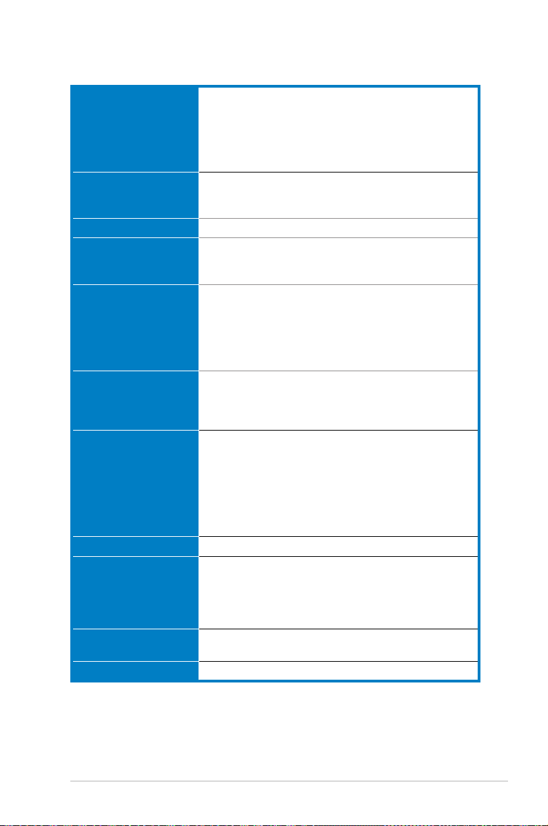
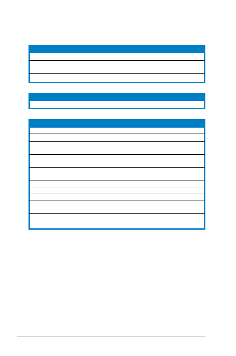
P5B-V specications summary
(continued on the next page)
CPU LGA775 socket for Intel® Core™2 Extreme / Core™2
Duo / Pentium
®
Extreme / Pentium® D / Pentium® 4 /
Celeron
®
D Processors
Compatible with Intel® 05B/05A/06 processors
Intel® Hyper-Threading Technology ready
* Refer to www.asus.com for Intel CPU support list
Chipset Northbridge: Intel® G965 with Intel® Clear Video
Technology and enhanced 3D feature
Southbridge: Intel® ICH8
System Bus 1066 / 800 / 533 MHz
Memory 4 x DIMM, max. 8GB, DDR2 800 / 667 / 533 MHz, non-ECC,
un-buffered memory
Dual channel memory architecture
VGA Intel® Graphics Media Accelerator X3000 integrated
High denition video processing with maximum
resolution of 2048 x 1536 pixels (@75Hz)
Maximum shared memory of 256 MB
Supports Microsoft® DX 9, OpenGL 1.5, and Pixel Shader
3.0
Expansion Slots 2 x PCI-E x16 slots (blue @ x16 mode, black @ x2 or x4
mode)
2 x PCI-E x1 slots
3 x PCI slots
Storage Southbridge Intel
®
ICH8
- 4 x SATA 3.0 Gb/s ports.
JMicron® JMB363 PATA and SATA controller
- 1 x UltraDMA 133/100/66 for up to 2 PATA devices
- 1 x Internal SATA 3.0 Gb/s port
- 1 x External SATA 3.0 Gb/s port support RAID 0, 1,
and JBOD conguration
LAN Marvell® 88E8001 PCI Gigabit LAN controller
Audio ADI® AD1988A 8-channel High Denition Audio CODEC
Support Jack-Sensing, Enumeration, Multi-streaming and
Jack-Retasking
Coaxial S/PDIF out port at back I/O
ASUS Noise Filter
IEEE 1394 TI® 1394a controller supports 2 x IEEE 1394a ports (one
at midboard; one at back panel)
USB 10 x USB2.0 ports (6 ports at mid-board, 4 ports at back panel)
xii
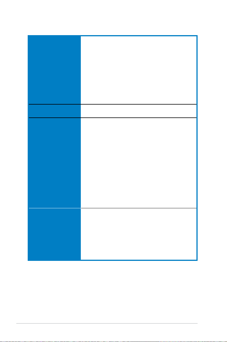
P5B-V specications summary
(continued on the next page)
ASUS AI Lifestyle
features
ASUS Quiet Thermal Solution:
- ASUS Advanced Q-Fan
- ASUS AI Gear
- ASUS AI Nap
- ASUS Fanless Design: Stack Cool 2
ASUS Crystal Sound
- Noise lter
ASUS EZ DIY
- ASUS Q-Connector
- ASUS O.C. Prole
- ASUS CrashFree BIOS 3
- ASUS EZ Flash 2
Other Features Multi-language BIOS
ASUS Music Alarm
ASUS Exclusive
Overclocking features
Intelligent overclocking tools:
- AI NOS™ (Non-delay Overclocking System)
- AI Overclocking (Intelligent CPU frequency tuner)
- ASUS PEG Link (Automatically performance tuning
for graphics card)
- ASUS AI Booster utility
Precision Tweaker:
- vDIMM: 4-step DRAM voltage control
- vCore: Adjustable CPU voltage at 6.25 mV increment
- vChipset: 4-step chipset voltage control
Stepless Frequency Selection (SFS) allows FSB
tuning from 100MHz to 500 MHz at 1MHz
increment; memory tuning from 533 to 1066MHz;
PCI-E tuning from 90 to 150MHz at 1 MHz increment
Overclocking protection:
- ASUS C.P.R. (CPU Parameter Recall)
Rear panel 1 x PS/2 keyboard port
1 x PS/2 mouse port
1 x VGA port
1 x External Serial ATA port
1 x Coaxial S/PDIF Out port
1 x IEEE1394a
1 x LAN (RJ-45) port
4 x USB 2.0/1.1 ports
8-channel audio ports
xiii
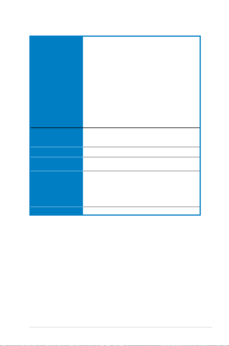
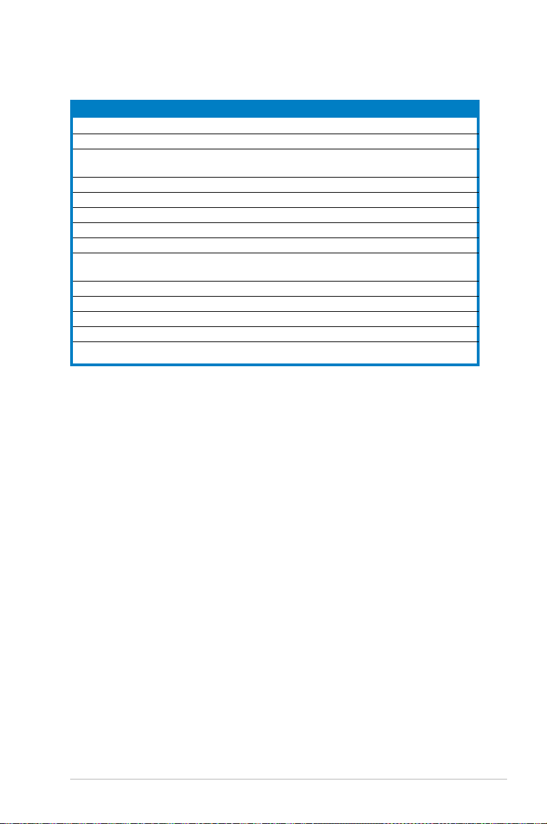
P5B-V specications summary
Internal connectors 3 x USB 2.0 connectors support six additional USB 2.0 ports
1 x Floppy disk drive connector
1 x IDE connector for two devices
5 x Serial ATA connectors
1 x CPU / 3 x Chassis / 1 x Power fan connectors
1 x ADH connector
1 x COM connector
1 x IEEE1394a connector
1 x S/PDIF Out connector
1 x Azalia Digital Header
Chassis intrusion connector
Front panel audio connector
CD audio in connector
24-pin ATX power connector
8-pin ATX 12 V power connector
System panel connector
BIOS features 8 Mb Flash ROM, AMI BIOS, PnP, DMI 2.0, WfM2.0,
SM BIOS 2.3, ACPI 2.0a, Multi-language BIOS, ASUS
EZ Flash 2, ASUS CrashFree BIOS 3
Manageability WfM 2.0, DMI 2.0, WOL by PME, WOR by PME, PXE, AOL
Power requirements ATX power supply with 24-pin and 8-pin 12V plugs
ATX 12V 2.0 compliant
Support CD contents Device drivers
ASUS PC Probe II
ASUS Update
ASUS AI Suite
ASUS Music Alarm
Anti-virus software (OEM version)
Form factor ATX form factor: 12 in x 9.6 in (30.5 cm x 24.4 cm)
*Specications are subject to change without notice.

xiv

1
Product
introduction
This chapter describes the motherboard
features and the new technologies
it supports.

ASUS P5B-V
Chapter summary
1
1.1 Welcome! ...................................................................................... 1-1
1.2 Package contents .........................................................................
1-1
1.3 Special features ............................................................................
1-2
ASUS P5B-V 1-1
1.1 Welcome!
Thank you for buying an ASUS® P5B-V motherboard!
The motherboard delivers a host of new features and latest technologies, making it
another standout in the long line of ASUS quality motherboards!
Before you start installing the motherboard, and hardware devices on it, check the
items in your package with the list below.
If any of the above items is damaged or missing, contact your retailer.
1.2 Package contents
Check your motherboard package for the following items.
Motherboard ASUS P5B-V
I/O modules 1 x 2-port USB 2.0 module
Cables 1 x Serial ATA cable kit
1 x Ultra DMA 133/100/66 cable
1 x Floppy disk drive cable
Accessories I/O shield
1 x ASUS Q-Connector Kit (USB, 1394, system
panel; Retail version only)
Application CD ASUS motherboard support CD
Documentation User guide
1-2 Chapter 1: Product introduction
1.3 Special features
1.3.1 Product highlights
Green ASUS
This motherboard and its packaging comply with the European Union’s Restriction
on the use of Hazardous Substances (RoHS). This is in line with the ASUS vision
of creating environment-friendly and recyclable products/packaging to safeguard
consumers’ health while minimizing the impact on the environment.
LGA775 Intel® Core™2 Processor Ready
This motherboard supports the latest Intel® Core™2 processor in the LGA775
package. With the new Intel® Core™ microarchitecture technology and 1066 /
800 MHz FSB, Intel® Core™2 processor is one of the most powerful and energy
efcient CPU in the world.
Intel G965 Chipset
The Intel® G965 Express Chipset boosts your gaming and multimedia experience
with the integrated graphics engine Intel® Graphics Media Accelerator X3000.
Delivering breakthrough increases in 3D, 2D, and video capabilities, the integrated
chipset meets the changing display requirements of visually rich applications. The
Intel® G965 Express features the Intel® Clear Video Technology, which trailblazes
new standards in high-denition video, crisp imaging, and accurate color control.
DDR2 memory support
The motherboard supports DDR2 memory that features data transfer rates of
800/667/533 MHz to meet the higher bandwidth requirements of the latest
3D graphics, multimedia, and Internet applications. The dual-channel DDR2
architecture doubles the bandwidth of your system memory to boost system
performance, eliminating bottlenecks with peak bandwidths of up to 12.8 GB/s.
Without restriction to the memory size across the two channels, the motherboard
allows you to install DIMMs with different memory size and enjoy dual-channel
feature at the same time. See pages 2-13 to 2-16 for details.
IEEE 1394a support
The IEEE 1394a interface provides high speed digital interface for audio/video
appliances such as digital television, digital video camcorders, storage peripherals
& other PC portable devices. See pages 2-23 and 2-26 for details.
ASUS P5B-V 1-3
Serial ATA 3.0 Gb/s technology and SATA on the go
This motherboard supports the next-generation hard drives based on the Serial
ATA (SATA) 3Gb/s storage specication, delivering enhanced scalability and
doubling the bus bandwidth for high-speed data retrieval and saves. The external
SATA port located at the back I/O provides smart setup and hot-plug functions.
Easily backup photos, videos and other entertainment contents to external devices.
See pages 2-22, 2-25, and 2-26 for details.
S/PDIF digital sound ready
This motherboard provides convenient connectivity to external home theater audio
systems via coaxial and optical S/PDIF-out (SONY-PHILIPS Digital Interface) jack.
It allows to transfer digital audio without converting to analog format and keeps the
best signal quality. See pages 2-23 and 2-27 for details.
High Denition Audio
Enjoy high-end sound quality on your PC! The onboard 8-channel HD audio (High
Denition Audio, previously codenamed Azalia) CODEC enables high-quality
192KHz/24-bit audio output, jack-sensing feature, retasking functions and
multi-streaming technology that simultaneously sends different audio streams to
different destinations. You can now talk to your partners on the headphone while
playing multi-channel network games. See page 5-27 for details.
1.3.2 ASUS AI Lifestyle features
ASUS Quiet Thermal Solution
ASUS Quiet Thermal solution makes system more stable and enhances the
overclocking capability.
AI Gear
AI Gear provides four modes that adjust the CPU frequency and Vcore
voltage minimizing system noise and power consumption. You can choose
the mode that best suits your computing needs. See page 5-23 for details.
AI Nap
With AI Nap, the system can continue running at minimum power and noise
when you are temporarily away. To wake the system and return to the OS
environment, simply click the mouse or press a key. See page 5-24 for details.
1-4 Chapter 1: Product introduction
ASUS Advanced Q-Fan
The ASUS Advanced Q-Fan technology on P5B-V is powered by Intel Quiet
System Technology. It makes the change of fan speed more smoothly, and
efciently reduces the noise caused by fans’ abruptly speeding up. Moreover,
ASUS Thermatat has a better control over a constant temperature system
environment. See page 5-25 for details.
Fanless Design - Stack Cool 2
ASUS Stack Cool 2 is a fan-less and zero-noise cooling solution that lowers
the temperature of critical heat generating components. The motherboard
uses a special design on the printed circuit board (PCB) to dissipate heat
these critical components generate.
ASUS Crystal Sound
This feature enhances speech-centric applications like Skype, online games, video
conference and recording.
Noise Filter
This feature detects repetitive and stationary noises (non-voice signals) like
computer fans, air conditioners, and other background noises then eliminates
it in the incoming audio stream while recording.
ASUS EZ DIY
ASUS EZ DIY feature collection provides you easy ways to install computer
components, update the BIOS or back up your favorite settings.
ASUS Q-Connector
ASUS Q-Connector allows you to easily connect or disconnect the chassis
front panel cables to the motherboard. This unique module eliminates the
trouble of connecting the system panel cables one at a time and avoiding
wrong cable connections. See page 2-33 for details.
ASUS O.C. Prole
The motherboard features the ASUS O.C. Prole that allows users to
conveniently store or load multiple BIOS settings. The BIOS settings can be
stored in the CMOS or a separate le, giving users freedom to share and
distribute their favorite settings. See page 4-38 for details.
ASUS P5B-V 1-5
ASUS CrashFree BIOS 3
The ASUS CrashFree BIOS 3 allows users to restore corrupted BIOS data
from a USB ash disk containing the BIOS le. See page 4-5 for details.
ASUS EZ Flash 2
EZ Flash 2 is a user-friendly BIOS update utility. Simply press the predened
hotkey to launch the utility and update the BIOS without entering the OS.
Update your BIOS easily without preparing a bootable diskette or using an
OS-based ash utility. See page 4-2 for details.
1.3.3 ASUS Special features
ASUS Multi-language BIOS
The multi-language BIOS allows you to select the language of your choice from the
available options. The localized BIOS setup menu helps you congure your system
easier and faster. See page 4-13 for details.
ASUS Music Alarm
Wake up to the music of your choice instead of the irritating sound of an alarm
clock. The ASUS Music Alarm gives you a personal wake-up call with your favorite
CD music when system is off. See page 4-36 and 5-17 for details.
ASUS MyLogo2™
This feature allows you to convert your favorite photo into a 256-color boot logo for
a more colorful and vivid image on your screen. See page 4-32 and 5-8 for details.
1.3.4 ASUS Intelligent Overclocking features
AI NOS™ (Non-Delay Overclocking System)
The patented ASUS Non-delay Overclocking System™ (AI NOS™) technology
auto-detects the CPU loading and dynamically overclocks the CPU speed when
needed. Unlike other dynamic overclocking techniques, AI NOS™ reacts much
faster to satisfy your need for speed. See page 5-22 for details.
1-6 Chapter 1: Product introduction
PEG Link Mode
This feature enhances your PCI Express graphics card performance. It allows the
motherboard to automatically adjust the PCI Express graphics link mode to the
correct frequency based on the system conguration. Four additional settings are
available for overclocking the PEG Link Mode.
Precision Tweaker
This feature allows you to ne tune the CPU/memory voltage and gradually
increase the memory Front Side Bus (FSB) and PCI Express frequency at 1MHz
increment to achieve maximum system performance.
AI NET2
AI NET2 is a BIOS-based diagnostic tool that detects and reports Ethernet cable
faults and shorts. With this utility, you can easily monitor the condition of the
Ethernet cable connected to the LAN (RJ-45) port. During the bootup process, AI
NET2 immediately diagnoses the LAN cable and reports shorts and faults up to
100 meters at 1 meter accuracy. See pages 4-23 and 5-10 for details.
C.P.R. (CPU Parameter Recall)
The C.P.R. feature of the motherboard BIOS allows automatic re-setting to the
BIOS default settings in case the system hangs due to overclocking. When the
system hangs due to overclocking, C.P.R. eliminates the need to open the system
chassis and clear the RTC data. Simply shut down and reboot the system, and the
BIOS automatically restores the CPU default setting for each parameter.
Due to chipset behavior, AC power off is required prior using C.P.R. function.

2
Hardware
information
This chapter lists the hardware setup
procedures that you have to perform
when installing system components. It
includes description of the jumpers and
connectors on the motherboard.

ASUS P5B-V
Chapter summary
2
2.1 Before you proceed ..................................................................... 2-1
2.2 Motherboard overview .................................................................
2-2
2.3 Central Processing Unit (CPU) ...................................................
2-6
2.4 System memory .........................................................................
2-13
2.5 Expansion slots ..........................................................................
2-17
2.6 Jumper ........................................................................................
2-20
2.7 Connectors .................................................................................
2-21
ASUS P5B-V 2-1
2.1 Before you proceed
Take note of the following precautions before you install motherboard components
or change any motherboard settings.
• Unplug the power cord from the wall socket before touching any
component.
• Use a grounded wrist strap or touch a safely grounded object or
a metal object, such as the power supply case, before handling
components to avoid damaging them due to static electricity.
• Hold components by the edges to avoid touching the ICs on them.
• Whenever you uninstall any component, place it on a grounded
antistatic pad or in the bag that came with the component.
• Before you install or remove any component, ensure
that the ATX power supply is switched off or the power cord is detached
from the power supply. Failure to do so may cause severe damage to the
motherboard, peripherals, and/or components.
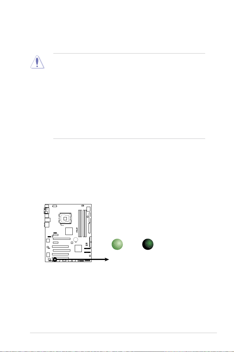
Onboard LED
The motherboard comes with a standby power LED that lights up to indicate
that the system is ON, in sleep mode, or in soft-off mode. This is a reminder
that you should shut down the system and unplug the power cable before
removing or plugging in any motherboard component. The illustration below
shows the location of the onboard LED.
R
P5B-V
P5B-V
Onboard LED
SB_PWR
ON
Standby
Power
OFF
Powered
Off
2-2 Chapter 2: Hardware information
R
P5B-V
2.2 Motherboard overview
Before you install the motherboard, study the conguration of your chassis to
ensure that the motherboard ts into it.
Make sure to unplug the power cord before installing or removing the
motherboard. Failure to do so can cause you physical injury and damage
motherboard components.
Do not overtighten the screws! Doing so can damage the motherboard.
2.2.1 Placement direction
When installing the motherboard, make sure that you place it into the chassis in the
correct orientation. The edge with external ports goes to the rear part of the chassis
as indicated in the image below.
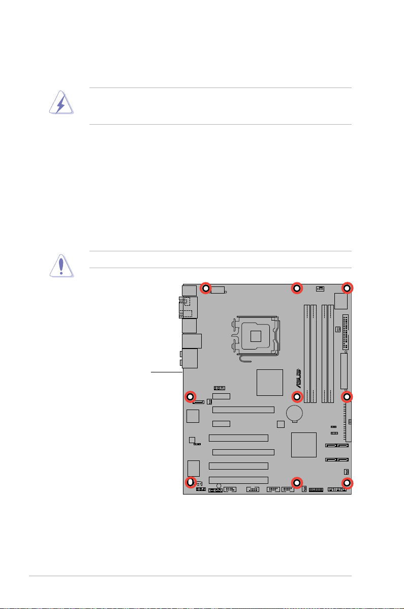
2.2.2 Screw holes
Place nine (9) screws into the holes indicated by circles to secure the motherboard
to the chassis.
Place this side towards
the rear of the chassis
ASUS P5B-V 2-3
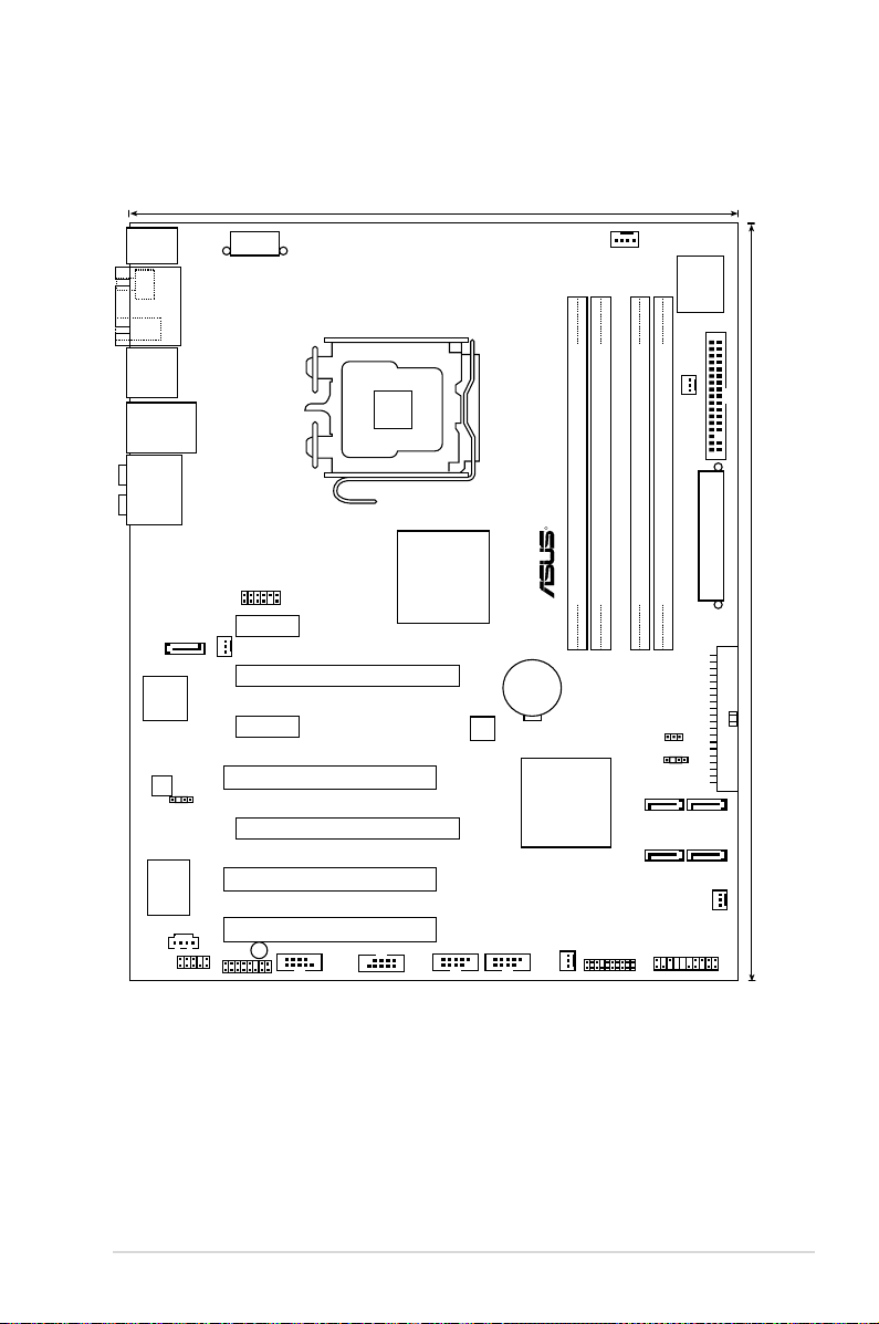
2.2.3 Motherboard layout
DDR2 DIMM_B2 (64 bit,240-pin module)
DDR2 DIMM_B1 (64 bit,240-pin module)
DDR2 DIMM_A2 (64 bit,240-pin module)
DDR2 DIMM_A1 (64 bit,240-pin module)
24.4cm (9.6in)
30.5cm (12.0in)
R
P5B-V
LGA775
Super I/O
CPU_FAN
PWR_FAN
FLOPPY
EATXPWR
PRI_IDE
SATA2 SATA1
SATA6 SATA5
SATA_RAID1
CHA_FAN3
CHA_FAN1
CHA_FAN2
PANELTPM
USB78USB56
USB910
COM1
SB_PWR
IE1394_2
ADH
AAFP
CD
PCI2
PCI1
PCI3
PCIEX16_2
PCIEX16_1
PCIEX1_2
PCIEX1_1
8Mb BIOS
AD1988A
Marvell
88E8001
JMB363
CR2032 3V
Lithium Cell
CMOS Power
Intel ICH 8
Intel MCH G965
PS/2KBMS
T: Mouse
B: Keyboard
SPDIF_O1
IE1394_1
SATA_USB12
LAN_USB34
AUDIO
EATX12V
CHASSIS
CLRTC
VGA
SPDIF_OUT
2-4 Chapter 2: Hardware information
2.2.4 Layout contents
Slots Page
1. DDR2 DIMM slots 2-13
2. PCI slots 2-19
3. PCI Express x1 slots 2-19
4. PCI Express x16 slot 2-19
Jumper Page
1. Clear RTC RAM (3-pin CLRTC) 2-20
Rear panel connectors Page
1. PS/2 mouse port (green) 2-21
2
. VGA port 2-21
3. USB 2.0 ports 1 and 2 2-21
4. LAN (RJ-45) port 2-21
5. Rear Speaker Out port (black) 2-21
6. Center/Subwoofer port (orange) 2-21
7. Line In port (light blue) 2-21
8. Line Out port (lime) 2-21
9. Microphone port (pink) 2-21
10. Side Speaker Out port (gray) 2-21
11. USB 2.0 ports 3 and 4 2-22
12. External SATA port 2-22
13. IEEE 1394a port 2-23
14. S/PDIF Out port 2-23
15. PS/2 keyboard port (purple) 2-23
ASUS P5B-V 2-5
Internal connectors Pag
e
1. Floppy disk drive connector (34-1 pin FLOPPY) 2-23
2. IDE connector (40-1 pin PRI_IDE) 2-24
3. ICH8 Serial ATA connectors (7-pin SATA1 [red], SATA2 [red],
2-25
SATA3 [black], SATA4 [black])
4. JMicron
®
JMB363 Serial ATA RAID connector (7-pin SATA_RAID [black] ) 2-26
5. IEEE 1394a port connector (10-1 pin IE1394_2 [red]) 2-26
6. Digital audio connector (4-1 pin SPDIF) 2-27
7. Optical drive audio connector (4-pin CD) 2-27
8. USB connectors (10-1 pin USB56, USB 78, USB910) 2-28
9. CPU, chassis, and power fan connectors (4-pin CPU_FAN, 2-29
3-pin CHA_FAN1, 3-pin CHA_FAN2, 3-pin CHA_FAN3, 3-pin PWR_FAN)
10. Serial port connector (10-1 pin COM1) 2-29
11. Chassis intrusion connector (4-1 pin CHASSIS) 2-30
12. Front panel audio connector (10-1 pin AAFP) 2-30
13. ATX power connectors (24-pin EATXPWR, 4-pin EATX12V) 2-31
14. System panel connector (20-8 pin PANEL) 2-32
2-6 Chapter 2: Hardware information
2.3 Central Processing Unit (CPU)
The motherboard comes with a surface mount LGA775 socket designed for
the Intel® Core™2/Pentium® D/Pentium® 4/Pentium® Extreme and Celeron
®
D
processors.
•
Upon purchase of the motherboard, make sure that the PnP cap is on
the socket and the socket contacts are not bent. Contact your retailer
immediately if the PnP cap is missing, or if you see any damage to the PnP
cap/socket contacts/motherboard components. ASUS will shoulder the cost
of repair only if the damage is shipment/transit-related.
•
Keep the cap after installing the motherboard. ASUS will process Return
Merchandise Authorization (RMA) requests only if the motherboard comes
with the cap on the LGA775 socket.
• The product warranty does not cover damage to the socket contacts
resulting from incorrect CPU installation/removal, or misplacement/loss/
incorrect removal of the PnP cap.
•
Make sure the AC power is off before you install the CPU.
• If installing a dual-core CPU, connect the chassis fan cable to the
CHA_FAN connector to ensure system stability.
 Loading...