


P4R800-VM
User Guide
Motherboard

E1662
Revised Edition V4
May 2004
Copyright © 2004 ASUSTeK COMPUTER INC. All Rights Reserved.
No part of this manual, including the products and software described in it, may be reproduced, transmitted, transcribed, stored in a retrieval system, or translated into any language in any form or by any means, except documentation kept by the purchaser for backup purposes, without the express written permission of ASUSTeK COMPUTER INC. (“ASUS”).
Product warranty or service will not be extended if: (1) the product is repaired, modified or altered, unless such repair, modification of alteration is authorized in writing by ASUS; or (2) the serial number of the product is defaced or missing.
ASUS PROVIDES THIS MANUAL “AS IS” WITHOUT WARRANTY OF ANY KIND, EITHER EXPRESS OR IMPLIED, INCLUDING BUT NOT LIMITED TO THE IMPLIED WARRANTIES OR CONDITIONS OF MERCHANTABILITY OR FITNESS FOR A PARTICULAR PURPOSE. IN NO EVENT SHALL ASUS, ITS DIRECTORS, OFFICERS, EMPLOYEES OR AGENTS BE LIABLE FOR ANY INDIRECT, SPECIAL, INCIDENTAL, OR CONSEQUENTIAL DAMAGES (INCLUDING DAMAGES FOR LOSS OF PROFITS, LOSS OF BUSINESS, LOSS OF USE OR DATA, INTERRUPTION OF BUSINESS AND THE LIKE), EVEN IF ASUS HAS BEEN ADVISED OF THE POSSIBILITY OF SUCH DAMAGES ARISING FROM ANY DEFECT OR ERROR IN THIS MANUAL OR PRODUCT.
SPECIFICATIONS AND INFORMATION CONTAINED IN THIS MANUAL ARE FURNISHED FOR INFORMATIONAL USE ONLY, AND ARE SUBJECT TO CHANGE AT ANY TIME WITHOUT NOTICE, AND SHOULD NOT BE CONSTRUED AS A COMMITMENT BY ASUS. ASUS ASSUMES NO RESPONSIBILITY OR LIABILITY FOR ANY ERRORS OR INACCURACIES THAT MAY APPEAR IN THIS MANUAL, INCLUDING THE PRODUCTS AND SOFTWARE DESCRIBED IN IT.
Products and corporate names appearing in this manual may or may not be registered trademarks or copyrights of their respective companies, and are used only for identification or explanation and to the owners’ benefit, without intent to infringe.
ii

Contents
Notices ........................................................................................... |
vi |
Safety information ......................................................................... |
vii |
About this guide ............................................................................ |
viii |
P4R800-VM specifications summary ............................................. |
ix |
Chapter |
1: Product introduction |
|
|
1.1 |
Welcome! ........................................................................... |
1-2 |
|
1.2 |
Package contents ............................................................... |
1-2 |
|
1.3 |
Special features.................................................................. |
1-2 |
|
1.4 |
Before you proceed ............................................................ |
1-5 |
|
1.5 |
Motherboard overview ........................................................ |
1-6 |
|
|
1.5.1 |
Motherboard layout ................................................ |
1-6 |
|
1.5.2 |
Placement direction ............................................... |
1-7 |
|
1.5.3 |
Screw holes ........................................................... |
1-7 |
1.6 |
Central Processing Unit (CPU)........................................... |
1-8 |
|
|
1.6.1 |
Overview ................................................................ |
1-8 |
|
1.6.2 |
Installing the CPU .................................................. |
1-9 |
1.7 |
System memory ............................................................... |
1-10 |
|
|
1.7.1 |
DIMM sockets location ......................................... |
1-10 |
|
1.7.2 |
Memory configurations ........................................ |
1-10 |
|
1.7.3 |
Installing a DIMM ................................................. |
1-12 |
1.8 |
Expansion slots ................................................................ |
1-12 |
|
|
1.8.1 |
Standard interrupt assignments ........................... |
1-13 |
|
1.8.2 |
IRQ assignments for this motherboard ................ |
1-13 |
|
1.8.3 |
PCI slots .............................................................. |
1-14 |
|
1.8.4 |
AGP slot ............................................................... |
1-14 |
1.9 |
Jumpers............................................................................ |
1-15 |
|
1.10 |
Connectors ....................................................................... |
1-17 |
|
|
1.10.1 |
Rear panel connectors ......................................... |
1-17 |
|
1.10.2 |
Internal connectors .............................................. |
1-18 |
iii

Contents
Chapter 2: BIOS information
2.1 Managing and updating your BIOS .................................... |
2-2 |
||
|
2.1.1 Creating a bootable floppy disk ............................. |
2-2 |
|
|
2.1.2 Using AFUDOS to copy the current BIOS ............. |
2-3 |
|
|
2.1.3 Using AFUDOS to update the BIOS ...................... |
2-4 |
|
|
2.1.4 Using ASUS EZ Flash to update the BIOS ............ |
2-5 |
|
|
2.1.5 Recovering the BIOS with CrashFree BIOS 2 ....... |
2-6 |
|
2.2 |
BIOS Setup program .......................................................... |
2-8 |
|
|
2.2.1 |
BIOS menu screen ................................................ |
2-9 |
|
2.2.2 |
Menu bar ................................................................ |
2-9 |
|
2.2.3 |
Navigation keys ..................................................... |
2-9 |
|
2.2.4 |
Menu items .......................................................... |
2-10 |
|
2.2.5 |
Sub-menu items ................................................... |
2-10 |
|
2.2.6 |
Configuration fields .............................................. |
2-10 |
|
2.2.7 |
Pop-up window .................................................... |
2-10 |
|
2.2.8 |
Scroll bar .............................................................. |
2-10 |
|
2.2.9 |
General help ........................................................ |
2-10 |
2.3 |
Main menu......................................................................... |
2-11 |
|
|
2.3.1 |
System Time ......................................................... |
2-11 |
|
2.3.2 |
System Date ......................................................... |
2-11 |
|
2.3.3 |
Legacy Diskette A ................................................. |
2-11 |
2.3.4Primary/IDE Master/Slave
|
|
Secondary IDE Master/Slave ............................... |
2-12 |
|
2.3.5 |
System Information .............................................. |
2-13 |
2.4 |
Advanced menu ............................................................... |
2-14 |
|
|
2.4.1 |
CPU Configuration ............................................... |
2-14 |
|
2.4.2 |
Chipset ................................................................. |
2-15 |
|
2.4.3 |
Onboard Devices Configuration ........................... |
2-17 |
|
2.4.4 |
PCI PnP ............................................................... |
2-18 |
2.5 |
Power menu ..................................................................... |
2-19 |
|
|
2.5.1 |
Suspend Mode ..................................................... |
2-19 |
|
2.5.2 Repost Video on S3 Resume............................... |
2-19 |
|
|
2.5.3 |
ACPI 2.0 Support ................................................. |
2-19 |
|
2.5.4 |
ACPI APIC Support .............................................. |
2-19 |
|
2.5.5 |
APM Configuration ............................................... |
2-20 |
|
2.5.6 |
Hardware Monitor ................................................ |
2-21 |
iv

Contents
2.6 |
Boot menu ........................................................................ |
2-22 |
|
|
2.6.1 |
Boot Device Priority ............................................. |
2-22 |
|
2.6.2 |
Boot Settings Configuration ................................. |
2-23 |
|
2.6.3 |
Security ................................................................ |
2-24 |
2.7 |
Exit menu ......................................................................... |
2-26 |
|
Chapter 3: Software support
3.1 |
Install an operating system................................................. |
3-2 |
|
3.2 |
Support CD information ...................................................... |
3-2 |
|
|
3.2.1 Running the support CD ........................................ |
3-2 |
|
|
3.2.2 |
Drivers menu ......................................................... |
3-3 |
|
3.2.3 |
Utilities menu ......................................................... |
3-3 |
|
3.2.4 |
ASUS Contact Information ..................................... |
3-4 |
v

Notices
Federal Communications Commission Statement
This device complies with FCC Rules Part 15. Operation is subject to the following two conditions:
•This device may not cause harmful interference, and
•This device must accept any interference received including interference that may cause undesired operation.
This equipment has been tested and found to comply with the limits for a Class B digital device, pursuant to Part 15 of the FCC Rules. These limits are designed to provide reasonable protection against harmful interference in a residential installation. This equipment generates, uses and can radiate radio frequency energy and, if not installed and used in accordance with manufacturer’s instructions, may cause harmful interference to radio communications. However, there is no guarantee that interference will not occur in a particular installation. If this equipment does cause harmful interference to radio or television reception, which can be determined by turning the equipment off and on, the user is encouraged to try to correct the interference by one or more of the following measures:
•Reorient or relocate the receiving antenna.
•Increase the separation between the equipment and receiver.
•Connect the equipment to an outlet on a circuit different from that to which the receiver is connected.
•Consult the dealer or an experienced radio/TV technician for help.
The use of shielded cables for connection of the monitor to the graphics card is required to assure compliance with FCC regulations. Changes or modifications to this unit not expressly approved by the party responsible for compliance could void the user’s authority to operate this equipment.
Canadian Department of Communications Statement
This digital apparatus does not exceed the Class B limits for radio noise emissions from digital apparatus set out in the Radio Interference Regulations of the Canadian Department of Communications.
This class B digital apparatus complies with Canadian ICES-003.
vi

Safety information
Electrical safety
•To prevent electrical shock hazard, disconnect the power cable from the electrical outlet before relocating the system.
•When adding or removing devices to or from the system, ensure that the power cables for the devices are unplugged before the signal cables are connected. If possible, disconnect all power cables from the existing system before you add a device.
•Before connecting or removing signal cables from the motherboard, ensure that all power cables are unplugged.
•Seek professional assistance before using an adpater or extension cord. These devices could interrupt the grounding circuit.
•Make sure that your power supply is set to the correct voltage in your area. If you are not sure about the voltage of the electrical outlet you are using, contact your local power company.
•If the power supply is broken, do not try to fix it by yourself. Contact a qualified service technician or your retailer.
Operation safety
•Before installing the motherboard and adding devices on it, carefully read all the manuals that came with the package.
•Before using the product, make sure all cables are correctly connected and the power cables are not damaged. If you detect any damage, contact your dealer immediately.
•To avoid short circuits, keep paper clips, screws, and staples away from connectors, slots, sockets and circuitry.
•Avoid dust, humidity, and temperature extremes. Do not place the product in any area where it may become wet.
•Place the product on a stable surface.
•If you encounter technical problems with the product, contact a qualified service technician or your retailer.
vii

About this guide
Conventions used in this guide
To make sure that you perform certain tasks properly, take note of the following symbols used throughout this guide.
WARNING: Information to prevent injury to yourself when trying to complete a task.
CAUTION: Information to prevent damage to the components when trying to complete a task.
IMPORTANT: Information that you MUST follow to complete a task.
NOTE: Tips and additional information to aid in completing a task.
Where to find more information
Refer to the following sources for additional information and for product and software updates.
1.ASUS websites
The ASUS websites worldwide provide updated information on ASUS hardware and software products. Refer to the ASUS contact information.
2.Optional documentation
Your product package may include optional documentation, such as warranty flyers, that may have been added by your dealer. These documents are not part of the standard package.
viii

P4R800-VM specifications summary
CPU |
Socket 478 for Intel® Pentium® 4 Northwood processor |
|
Intel® Hyper-Threading technology ready |
|
New power design for next generation Intel® Prescott CPU |
Chipset |
|
ATI RADEON™ 9100 IGP |
|
|
ATI IXP200 |
Front Side Bus (FSB) |
|
800/533/400 MHz |
|
Memory |
|
4 x 184-pin DDR DIMM sockets |
|
|
Up to 4 GB system memory |
|
Supports unbuffered non-ECC PC3200*/2700/2100/1600 |
|
DDR DIMMs.(*Supports one single-sided PC3200 [DDR400] |
|
DIMM per channel only) |
Expansion slots |
|
1 x AGP 8X/4X (1.5V only) |
|
|
3 x PCI |
VGA |
|
ATI Radeon™ 9200 integrated graphics |
|
Storage |
|
2 x UltraATA100/66, PIO Mode 0 ~ 4 |
|
Audio |
|
ADI AD1888 6-channel audio CODEC |
|
LAN |
|
IXP200 built in MAC with Realtek 8201BL/CL LAN PHY |
|
Hardware monitoring |
|
Super I/O integrated monitoring of CPU/chassis fan rotation |
|
|
and MB/CPU temperature |
Special features |
|
Digital audio via an S/PDIF out inteface |
|
|
TV out support |
|
ASUS MyLogo2 |
|
ASUS EZ Flash |
|
ASUS Q-Fan Technology |
|
ASUS CrashFree BIOS2 |
Rear panel I/O |
|
1 x Parallel port |
|
|
1 x VGA port |
|
1 x S/PDIF port |
|
1 x PS/2 keyboard port |
|
1 x PS/2 mouse port |
|
4 x USB 2.0/USB 1.1 ports |
|
1 x LAN (RJ-45) port |
|
Line In/Line Out/Microphone ports |
|
|
|
(continued on the next page) |
ix

P4R800-VM specifications summary
Internal I/O |
1 x USB 2.0/1.1 connector for 2 additional USB ports |
|
CPU and chassis fan connectors |
|
20-pin/4-pin ATX 12V power connectors |
|
CD/AUX audio connectors |
|
Front panel audio connector |
|
Panel connectors |
|
COM connector |
|
TV-out connector |
|
Power LED connector** |
|
|
BIOS features |
4Mb Flash EEPROM, AMI BIOS with enhanced ACPI, DMI, |
|
Green,PnP features, SM BIOS2.3, ASUS CrashFree BIOS2, |
|
ASUS MyLogo2, and ASUS EZ Flash |
|
|
Industry standard |
PCI 2.2, USB 2.0/1.1 |
|
|
Form Factor |
Micro-ATX form factor: 9.6 in x 9.6 in (24.5 cm x 24.5 cm) |
|
|
Support CD contents |
Device drivers |
|
ASUS PC Probe |
|
ASUS LiveUpdate |
|
ASUS Screensaver |
|
Adobe Acrobat Reader |
|
Trend Micro™ PC-cillin 2002 anti-virus software |
|
Microsoft® DirectX 8.1 |
|
|
*Specifications are subject to change without notice.
**Present only on PCB version 1.03 or later.
x
Chapter 1
This chapter describes the features of this motherboard. It includes brief descriptions of the motherboard components, and illustrations of the layout, jumper settings, and connectors.
Product introduction
1.1Welcome!
Thank you for buying the ASUS® P4R800-VM motherboard!
The ASUS P4R800-VM motherboard delivers a host of new features and latest technologies making it another standout in the long line of ASUS quality motherboards!
Before you start installing the motherboard, and hardware devices on it, check the items in your package with the list below.
1.2Package contents
Check your P4R800-VM package for the following items.
ASUS P4R800-VM motherboard
Micro-ATX form factor: 9.6 in x 9.6 in (24.5 cm x 24.5 cm)
ASUS P4R800-VM series support CD
Serial (COM) port module and cable
80-conductor Ultra ATA IDE cable
Ribbon cable for a 3.5-inch floppy drive
I/O shield
Bag of extra jumper caps
User Guide
If any of the above items is damaged or missing, contact your retailer.
1.3Special features
Intel® 800MHz FSB CPU support 
The motherboard comes with a 478-pin surface mount, Zero Insertion Force (ZIF) socket for the Intel® Pentium® 4 Northwood/Willamette processor in the 478-pin package with 512/256KB L2 cache on 0.13 micron process. This motherboard supports 800/533/400 MHz system front side bus that allows 6.4GB/s, 4.3GB/s and 3.2GB/s data transfer rates, respectively. The P4R800-VM also supports the Intel® Hyper-Threading Technology and the next-generation Intel® Prescott CPU.
See page 1-8.
ATi RADEON 9100 IGP/IXP200 chipset
The embedded RADEON™ 9100 Integrated Graphics Processor (IGP) Northbridge and the IXP200 Southbridge chipset control all interfaces to ensure an efficient and reliable computing performance. See page 2-15 and 2-16.
1-2 |
Chapter 1: Product introduction |

The RADEON™ 9100 IGP provides processor interface with 800/533/400 MHz frequency, system memory interface at 400/333/266/200MHz operation, and 1.5V AGP interface that supports AGP 8X specification.
The IXP 200 (SB200) is a subsystem that integrates various I/O functions including dual-channel ATA100 bus master IDE controller, up to six USB 2.0/1.1 ports, I/O APIC interrupt and Ethernet controllers, and LPC, AC’97 2.2 interfaces, Ethernet controller, and PCI 2.2 interface. The proprietary A-Link interface connects the IXP 200 with the RADEON™ IGP at up to 266MB/s data transfer rate.
Dual channel DDR400 memory support 
The motherboard supports single or dual memory architecture for up to 4GB system memory. Four 184-pin DIMM sockets are available for installation of unbuffered non-ECC PC3200/2700/2100/1600 DDR DIMMs. See page 1-10.
ATi RADEON 9200-based GPU 
Integrated in the IGP chipset is the ATI RADEON™ 9200-based 2D/3D graphics engine with maximum 128MB shared display memory. The integrated graphics also supports TV out function through a separate TV out module (AV/S). The RADEON 9200-based GPU achieves a maximum resolution of 2048x1536 at 32bpp. See page 1-20.
Integrated 10/100 Mbps LAN MAC 
The integrated MAC in the IXP 200 Southbridge works with the onboard Realtek 8201BL/CL LAN PHY to fully support 10BASE-T/ 100BASE-TX Ethernet networking. See page 1-17.
SoundMAX digital audio system
The SoundMax Digital Audio System is the industry’s highest performance and most reliable audio solution for business professionals, audiophiles, musicians, and gamers. SoundMAX Digital Audio System can output 5.1 channel surround and features state-of-the-art DLS2 MIDI synthesizer with Yamaha DLSbyXG sound set, 5.1 Virtual Theater™ and supports all major game audio technologies including Microsoft DirectX™8.0, Microsoft DirectSound 3D™, A3D, MacroFX, ZoomFX, MultiDrive 5.1 and EAX. See page 1-17.
USB 2.0 connectivity 
The motherboard rear panel comes with four (4) Universal Serial Bus (USB) ports to connect USB 2.0 devices. A USB header is also available at mid-board to accommodate a USB module for two (2) additional USB ports. The USB ports and header comply with USB 2.0 specification that supports up to 480 Mbps connection speed. This speed advantage over the conventional USB 1.1 (12 Mbps) allows faster Internet connection, interactive gaming, and simultaneous running of high-speed peripherals. USB 2.0 is backward compatible with USB 1.1.
See pages 1-17 and 1-21.
ASUS P4R800-VM motherboard user guide |
1-3 |

CrashFree BIOS2
This feature allows you to restore the original BIOS data from the support CD, or from a bootable floppy disk, when the BIOS codes and data are corrupted. This protection eliminates the need to buy a replacement ROM chip. See page 2-6.
ASUS Q-Fan technology 
The ASUS Q-Fan technology smartly adjusts the fan speeds according to the system loading to ensure quiet, cool, and efficient operation. See page 2-21.
ASUS EZ Flash BIOS
With the ASUS EZ Flash, you can easily update the system BIOS even before loading the operating system. No need to use a DOS-based utility or boot from a floppy disk. See page 2-5.
ASUS MyLogo2 
This new feature present in the motherboard allows you to personalize and add style to your system with customizable boot logos. The ASUS MyLogo2 is automatically installed when you install the ASUS Update utility from Utilities menu in the support CD. See page 3-3.
1-4 |
Chapter 1: Product introduction |
1.4Before you proceed
Take note of the following precautions before you install motherboard components or change any motherboard settings.
1. Unplug the power cord from the wall socket before touching any component.
2.Use a grounded wrist strap or touch a safely grounded object or to a metal object, such as the power supply case, before handling components to avoid damaging them due to static electricity.
3.Hold components by the edges to avoid touching the ICs on them.
4.Whenever you uninstall any component, place it on a grounded antistatic pad or in the bag that came with the component.
5.Before you install or remove any component, ensure that the ATX power supply is switched off or the power cord is detached from the power supply. Failure to do so may cause severe damage to the motherboard, peripherals, and/or components.
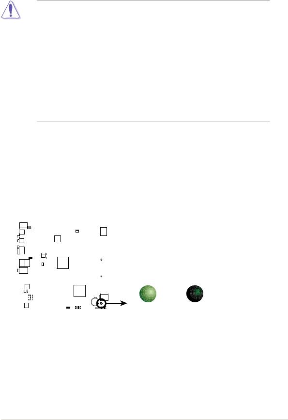
Onboard LED
The motherboard comes with a stand-by power LED. The green LED lights up to indicates that the system is ON, in sleep mode, or in soft-off mode. The LED reminds you to shut down the system and unplug the power cable before removing or plugging in any motherboard component. The illustration below shows the location of the onboard LED.
|
|
|
|
|
|
|
|
|
|
|
|
|
|
|
|
|
|
|
|
|
|
|
|
|
|
|
|
|
|
|
|
|
|
|
|
|
|
|
|
|
|
|
|
|
|
|
|
|
|
|
|
|
|
|
|
|
|
|
|
|
|
|
|
|
|
|
|
|
|
|
|
|
|
|
|
|
|
|
|
|
|
|
|
|
|
|
|
|
|
|
|
|
|
|
|
|
|
|
|
|
|
|
|
|
|
|
|
|
|
|
|
|
|
|
|
|
|
|
|
|
|
|
|
|
|
|
|
|
|
|
|
|
|
|
|
|
|
|
|
|
|
|
|
|
|
|
|
|
|
|
|
|
|
|
|
|
|
|
|
|
|
|
|
|
|
|
|
|
|
|
|
P4R800-VM |
|
|
|
|
|
|
|
|
|
|
|
|
|
|
|
|
SB_PWR1 |
|||||
|
|
|
|
|
|
|
|
|
|
|
|
|
|
|
|
|
|
|
|
|
|
|
|
|
|
|
|
|
|
|
|
|||||||
|
|
|
|
|
|
|
|
|
|
|
|
|
|
|
|
|
|
|
|
|
|
|
|
|
|
|
|
|
|
|
|
|||||||
|
|
|
|
|
|
|
|
|
|
|
|
|
|
|
|
|
|
|
|
|
|
|
|
|
|
|
|
|
|
|
|
|||||||
|
|
|
|
|
|
|
|
|
|
|
|
|
|
|
|
|
|
|
|
|
|
|
|
|
|
|
|
|
|
|
|
|||||||
|
|
|
|
|
|
|
|
|
|
|
|
|
|
|
|
|
|
|
|
|
|
|
|
|
|
|
|
|
|
|
|
|||||||
|
|
|
|
|
|
|
|
|
|
|
|
|
|
|
|
|
|
|
|
|
|
|
|
|
|
|
|
|
|
|
|
|||||||
|
|
|
|
|
|
|
|
|
|
|
|
|
|
|
|
|
|
|
|
|
|
|
|
|
|
|
|
|
|
|||||||||
|
|
|
|
|
|
|
|
|
|
|
|
|
|
|
|
|
|
|
|
|
|
|
|
|
|
|
|
|
|
|
|
|
|
|
|
|
||
|
|
|
|
|
|
|
|
|
|
|
|
|
|
|
|
|
|
|
|
|
|
|
|
|
|
|
|
|
|
|
|
|
|
|
|
|
||
|
|
|
|
|
|
|
|
|
|
|
|
|
|
|
|
|
|
|
|
|
|
|
|
|
|
|
|
|
|
|
|
|
|
|
|
|
||
|
|
|
|
|
|
|
|
|
|
|
|
|
|
|
|
|
|
|
|
|
|
|
|
|
|
|
|
|
|
|
|
|
|
|
|
|
||
|
|
|
|
|
|
|
|
|
|
|
|
|
|
|
|
|
|
|
|
|
|
|
|
|
|
|
|
|
|
|
|
|
|
|
|
|
ON |
OFF |
|
|
|
|
|
|
|
|
|
|
|
|
|
|
|
|
|
|
|
|
|
|
|
|
|
|
|
|
|
|
|
|
|
|
|
|
|
||
|
|
|
|
|
|
|
|
|
|
|
|
|
|
|
|
|
|
|
|
|
|
|
|
|
|
|
|
|
|
|
|
|
|
|
|
|
||
|
|
|
|
|
|
|
|
|
|
|
|
|
|
|
|
|
|
|
|
|
|
|
|
|
|
|
|
|
|
|
|
|
|
|
|
|
||
|
|
|
|
|
|
|
|
|
|
|
|
|
|
|
|
|
|
|
|
|
|
|
|
|
|
|
|
|
|
|
|
|
|
|
|
|
||
|
|
|
|
|
|
|
|
|
|
|
|
|
|
|
|
|
|
|
|
|
|
|
|
|
|
|
|
|
|
|
|
|
|
|
|
|
||
|
P4R800-VM Onboard LED |
Standby |
Powered |
|||||||||||||||||||||||||||||||||||
|
Power |
Off |
||||||||||||||||||||||||||||||||||||
ASUS P4R800-VM motherboard user guide |
1-5 |
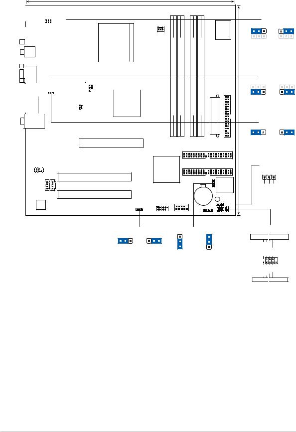
1.5Motherboard overview
1.5.1 Motherboard layout
24.5cm (9.6in)
|
|
|
|
|
|
|
|
|
|
|
|
|
PS/2KBMS |
|
|
|
|
|
|
|
|
|
|
|
T: Mouse |
|
|
|
|
|
|
|
|
|
|
|
B: Keyboard |
|
|
|
|
|
|
|
|
|
KBPWR1 |
|
|
|
|
|
|
|
|
|
|
|
USBPW12 |
|
USB1 |
|
|
|
|
|
|
|
|
|
|
|
|
|
Socket 478 |
||||
|
USB2 |
|
|
|
|
|
|
|
|
|
|
|
|
|
|
|
|
|
|
|
|
|
|
|
|
|
|
|
|
|
|
|
|
|
|
|
|
|
|
|
|
|
|
|
|
|
|
|
|
|
|
|
|
|
|
|
|
|
|
|
SPDIF_O |
PARALLELPORT |
|
|
|
|
|
|
|
|
|
|
|
||||||
|
|
|
|
|
|
|
|
|
|
|
|
|
|
|
|
|
|
||
|
VGA1 |
|
|
|
|
|
|
|
|
|
|
|
|
|
|
|
|
|
|
|
|
|
|
|
|
|
|
|
|
|
|
|
|
|
|
|
|
|
|
|
|
|
|
USBPW34 |
|
|
|
|
|
|
|
|
|
|
|
|
|||
|
|
|
|
|
|
|
|
|
|
|
|
|
|
|
|
||||
|
|
|
|
|
|
|
ATX12V1 |
|
|
|
|
|
ATI |
||||||
|
|
|
|
|
|
|
TV-OUT1 |
|
|
|
|||||||||
|
USB2.0 |
Top: |
|
|
|
|
|
|
|
|
|
|
|
|
RADEON |
||||
|
T: USB3 |
RJ-45 |
|
|
|
|
|
|
|
|
|
|
9100 |
|
|||||
|
B: USB4 |
|
|
|
|
|
|
|
|
|
|
|
|
|
|
|
|
IGP |
|
|
|
|
|
|
|
|
CHA_FAN1 |
|
|
|
|||||||||
|
|
|
|
|
|
|
|
|
|
|
|
||||||||
Top:Line In
Center:Line Out
Below:Mic In
P4R800-VM
Accelerated Graphics Port (AGP1)
|
|
|
RTL |
|
|
||
|
|
8201BL |
|
PCI1 |
|||
|
|
|
|
|
|
|
|
|
|
|
|
|
|
|
|
|
|
|
|
|
|
|
|
FP_AUDIO1
PCI2


 AUX1
AUX1
CD1
PCI3
AD1888 |
USBPW56 |
CODEC |
|
|
|
|
|
Super I/O |
|
|
KBPWR1 |
|
|
|
|
|
|
|
|
1 |
2 |
2 |
3 |
|
CPU_FAN1 |
module)pin-bit,184 |
module)pin-bit,184 |
module)pin-bit,184 |
|
|
|
|
|
|
|
module)pin-bit,184 |
|
|
|
|
+5V |
+5VSB |
||||
|
|
|
|
|
|
|
|
|||
|
|
|
|
|
|
|
(Default) |
|
|
|
(64 |
(64 |
(64 |
(64 |
|
|
|
|
USBPW12 |
|
|
|
|
|
1 |
2 |
2 |
3 |
||||
DIMMDDR A1 |
DIMMDDR A2 |
DIMMDDR B1 |
DIMMDDR B2 |
ConnectorPowerATX |
|
(9.6in)24.5cm |
||||
FLOPPY1 |
|
+5V |
+5VSB |
|||||||
|
|
|
|
|
|
|
(Default) |
|
|
|
|
|
|
|
|
|
|
|
USBPW34 |
|
|
|
|
|
|
|
|
|
1 |
2 |
2 |
3 |
|
|
|
|
|
|
|
|
+5V |
+5VSB |
|
|
|
|
|
|
|
|
(Default) |
|
|
|
|
|
|
|
|
SEC_IDE1 |
|
|
|
|
|
ATI |
|
|
|
|
PRI_IDE1 |
|
|
PLED1 |
|
|
IXP200 |
|
|
|
|
|
|
|
1 |
|
|
|
|
|
CLRTC1 |
|
4Mbit |
|
|
|
|
|
|
|
|
Lithium Cell |
|
Firmware |
|
|
PLED+ |
NC PLED- |
|
|
|
|
|
Hub |
|
|
|
|||
|
|
|
|
|
|
|
|
|
|
|
|
|
|
CR2032 3V |
|
|
|
|
|
|
|
|
|
|
CMOS Power |
|
SB_PWR1 |
|
|
|
|
|
|
COM1 |
|
|
|
|
|
|
|
|
|
USB56 |
|
|
|
PLED1 |
|
|
|
|
|
|
|
|
|
|
|
|
|
|
|
||
|
|
|
SPEAK1 F_PANEL1 |
|
|
|
|
|
||
|
USBPW56 |
|
CLRTC1 |
||
1 |
2 |
2 |
3 |
|
3 |
|
|
|
|
2 |
|
|
|
|
|
2 |
|
|
+5V |
+5VSB |
1 |
|
|
(Default) |
|
|
Normal |
Clear CMOS |
|
|
|
|
|
(Default) |
|
F_PANEL1
Power LED 
 Power Switch
Ground
Power Switch
Power LED-
Power LED+
F_PANEL1 
Reset
Ground
IDE LED-
IDE LED+
IDE_LED 
 Reset Switch
* Requires an ATX power supply.
1-6 |
Chapter 1: Product introduction |

1.5.2 Placement direction
When installing the motherboard, make sure that you place it into the chassis in the correct orientation. The edge with external ports goes to the rear part of the chassis as indicated in the image below.
1.5.3 Screw holes
Place eight (8) screws into the holes indicated by circles to secure the motherboard to the chassis.
Do not overtighten the screws! Doing so may damage the motherboard.
Place this side towards the rear of the chassis
ASUS P4R800-VM motherboard user guide |
1-7 |
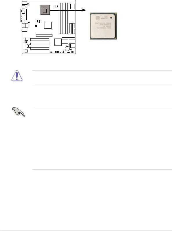
1.6Central Processing Unit (CPU)
1.6.1 Overview
The Intel® Pentium® 4 processor has a gold triangular mark on one corner. This mark indicates the processor Pin 1 that should match a specific corner of the CPU socket.
 Gold Arrow
P4R800-VM
P4R800-VM Socket 478
Incorrect installation of the CPU into the socket may bend the pins and severely damage the CPU!
Notes on Intel® Hyper-Threading Technology
• Hyper-Threading Technology is supported under Windows® XP and Linux 2.4.x (kernel) and later versions only. Under Linux, use the Hyper-Threading compliler to compile the code. If you are using any other operating systems, disable the Hyper-Threading Techonology item in BIOS to ensure system stability and performance.
•It is recommended that you install Windows® XP Service Pack 1.
•Make sure to enable the Hyper-Threading Technology item in BIOS before installing a supported operating system.
•For more information on Hyper-Threading Technology, visit www.intel.com/ info/hyperthreading.
1-8 |
Chapter 1: Product introduction |

1.6.2 Installing the CPU
Follow these steps to install a CPU.
1.Locate the 478-pin ZIF socket on the motherboard.
2.Unlock the socket by pressing the lever sideways, then lift it up to a 90°- 100° angle.
Socket
Make sure that the socket lever is lifted up to 90°-100° angle, otherwise the CPU does not fit in completely.
3.Position the CPU above the socket such that its marked corner matches the base of the socket lever.
4.Carefully insert the CPU into the socket until it fits in place.
90 - 100
Gold Mark
The CPU fits only in one correct orientation. DO NOT force the CPU into the socket to prevent bending the pins and damaging the CPU!
5.When the CPU is in place, push down the socket lever to secure the CPU. The lever clicks on the side tab to indicate that it is locked.
6.Install a CPU heatsink and fan following the instructions that came with the heatsink package.
7.Connect the CPU fan cable to the CPU_FAN1 connector on the motherboard.
ASUS P4R800-VM motherboard user guide |
1-9 |
1.7System memory
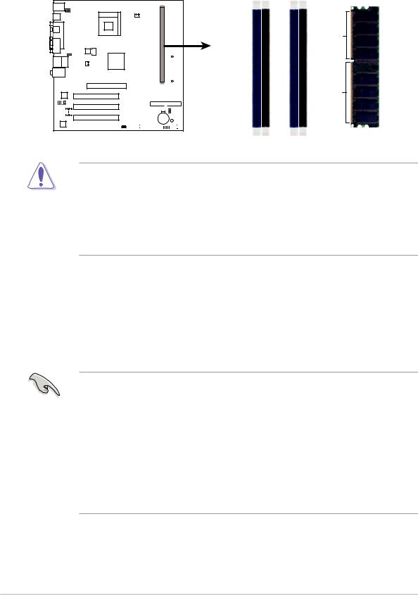
1.7.1 DIMM sockets location
The following figure illustrates the location of the DDR DIMM sockets.
P4R800-VM
|
|
|
|
|
|
|
|
|
|
|
|
DIMM A1 |
DIMM A2 |
DIMM B1 |
DIMM B2 |
Pins |
|
|
|
|
|
|
|
|
|
|
|
|
|||||
|
|
|
|
|
|
|
|
|
|
|||||||
|
|
|
|
|
|
|
|
|
|
|||||||
|
|
|
|
|
|
|
|
|
|
|
|
|||||
|
|
|
|
|
|
|
|
|
|
|
|
|
|
|
|
80 |
|
|
|
|
|
|
|
|
|
|
|
|
|
|
|
|
104 Pins |
|
|
|
|
|
|
|
|
|
|
|
|
|
|
|
|
|
|
|
|
|
|
|
|
|
|
|
|
|
|
|
|
|
|
|
|
|
|
|
|
|
|
|
|
|
|
|
|
|
|
|
|
|
|
|
|
|
|
|
|
|
|
|
|
|
|
|
|
|
|
|
|
|
|
|
|
|
|
|
|
|
|
|
|
|
|
|
|
|
|
|
|
|
|
|
|
|
|
|
|
|
|
|
|
|
|
|
|
|
|
|
|
|
|
|
|
|
|
|
P4R800-VM 184-Pin DDR DIMM Sockets
Make sure to unplug the power supply before adding or removing DIMMs or other system components. Failure to do so may cause severe damage to both the motherboard and the components.
When installing long AGP cards, it is recommended to install the memory modules first. Long AGP cards, when installed, may interfere with the memory sockets.
1.7.2 Memory configurations
You may install 64MB, 128MB, 256MB, 512MB, and 1GB DDR DIMMs into the DIMM sockets using the memory configurations in this section.
Important notes
•Installing DDR DIMMs other than the recommended configurations may cause memory sizing error or system boot failure. Use any of the recommended configurations in Table 1.
•A three-DIMM configuration is not supported on this motherboard
•In dual-channel configurations, always install an identical (the same type and size) DDR DIMM pair on sockets of the same color.
•Always install DIMMs with the same CAS latency. For optimum compatibility, it is recommended that you obtain memory modules from the same vendor.
1-10 |
Chapter 1: Product introduction |
 Loading...