


P4P800-X
User Guide
Motherboard

E1718
First Edition
July 2004
Copyright © 2003 ASUSTeK COMPUTER INC. All Rights Reserved.
No part of this manual, including the products and software described in it, may be reproduced, transmitted, transcribed, stored in a retrieval system, or translated into any language in any form or by any means, except documentation kept by the purchaser for backup purposes, without the express written permission of ASUSTeK COMPUTER INC. (“ASUS”).
Product warranty or service will not be extended if: (1) the product is repaired, modified or altered, unless such repair, modification of alteration is authorized in writing by ASUS; or (2) the serial number of the product is defaced or missing.
ASUS PROVIDES THIS MANUAL “AS IS” WITHOUT WARRANTY OF ANY KIND, EITHER EXPRESS OR IMPLIED, INCLUDING BUT NOT LIMITED TO THE IMPLIED WARRANTIES OR CONDITIONS OF MERCHANTABILITY OR FITNESS FOR A PARTICULAR PURPOSE. IN NO EVENT SHALL ASUS, ITS DIRECTORS, OFFICERS, EMPLOYEES OR AGENTS BE LIABLE FOR ANY INDIRECT, SPECIAL, INCIDENTAL, OR CONSEQUENTIAL DAMAGES (INCLUDING DAMAGES FOR LOSS OF PROFITS, LOSS OF BUSINESS, LOSS OF USE OR DATA, INTERRUPTION OF BUSINESS AND THE LIKE), EVEN IF ASUS HAS BEEN ADVISED OF THE POSSIBILITY OF SUCH DAMAGES ARISING FROM ANY DEFECT OR ERROR IN THIS MANUAL OR PRODUCT.
SPECIFICATIONS AND INFORMATION CONTAINED IN THIS MANUAL ARE FURNISHED FOR INFORMATIONAL USE ONLY, AND ARE SUBJECT TO CHANGE AT ANY TIME WITHOUT NOTICE, AND SHOULD NOT BE CONSTRUED AS A COMMITMENT BY ASUS. ASUS ASSUMES NO RESPONSIBILITY OR LIABILITY FOR ANY ERRORS OR INACCURACIES THAT MAY APPEAR IN THIS MANUAL, INCLUDING THE PRODUCTS AND SOFTWARE DESCRIBED IN IT.
Products and corporate names appearing in this manual may or may not be registered trademarks or copyrights of their respective companies, and are used only for identification or explanation and to the owners’ benefit, without intent to infringe.
ii

Contents
Notices ........................................................................................... |
vi |
Safety information ......................................................................... |
vii |
About this guide............................................................................ |
viii |
Conventions used in this guide ........................................... |
viii |
Where to find more information ........................................... |
viii |
P4P800-X specification summary .................................................. |
ix |
Chapter |
1: Product introduction |
|
|
1.1 |
Welcome! ........................................................................... |
1-2 |
|
1.2 |
Package contents ............................................................... |
1-2 |
|
1.3 |
Special features.................................................................. |
1-2 |
|
1.4 |
Before you proceed ............................................................ |
1-4 |
|
1.5 |
Motherboard overview ........................................................ |
1-5 |
|
|
1.5.1 |
Motherboard layout ................................................ |
1-5 |
|
1.5.2 |
Placement direction ............................................... |
1-6 |
|
1.5.3 |
Screw holes ........................................................... |
1-6 |
1.6 |
Central Processing Unit (CPU)........................................... |
1-7 |
|
|
1.6.1 |
Overview ................................................................ |
1-7 |
|
1.6.2 |
Installing the CPU .................................................. |
1-8 |
1.7 |
System memory ................................................................. |
1-9 |
|
|
1.7.1 |
DIMM sockets location ........................................... |
1-9 |
|
1.7.2 |
Memory configurations .......................................... |
1-9 |
|
1.7.3 |
Installing a DIMM ................................................. |
1-12 |
1.8 |
Expansion slots ................................................................ |
1-13 |
|
|
1.8.1 |
Standard interrupt assignments ........................... |
1-13 |
|
1.8.2 |
IRQ assignments for this motherboard ................ |
1-13 |
|
1.8.3 |
PCI slots .............................................................. |
1-14 |
|
1.8.4 |
AGP slot ............................................................... |
1-14 |
1.9 |
Jumpers............................................................................ |
1-15 |
|
1.10 |
Connectors ....................................................................... |
1-17 |
|
|
1.10.1 |
Rear panel connectors ......................................... |
1-17 |
|
1.10.2 |
Internal connectors .............................................. |
1-18 |
iii

Contents
Chapter 2: BIOS Information
2.1 Managing and updating your BIOS .................................... |
2-2 |
||
|
2.1.1 Creating a bootable floppy disk ............................. |
2-2 |
|
|
2.1.2 Using AFUDOS to copy the current BIOS ............. |
2-3 |
|
|
2.1.3 Using AFUDOS to update the BIOS ...................... |
2-3 |
|
|
2.1.4 Using ASUS EZ Flash to update the BIOS ............ |
2-5 |
|
|
2.1.5 Recovering the BIOS with CrashFree BIOS 2 ....... |
2-6 |
|
2.2 |
BIOS Setup program .......................................................... |
2-8 |
|
|
2.2.1 |
BIOS menu screen ................................................ |
2-9 |
|
2.2.2 |
Menu bar ................................................................ |
2-9 |
|
2.2.3 |
Navigation keys ..................................................... |
2-9 |
|
2.2.4 |
Menu items .......................................................... |
2-10 |
|
2.2.5 |
Sub-menu items ................................................... |
2-10 |
|
2.2.6 |
Configuration fields .............................................. |
2-10 |
|
2.2.7 |
Pop-up window .................................................... |
2-10 |
|
2.2.8 |
Scroll bar .............................................................. |
2-10 |
|
2.2.9 |
General help ........................................................ |
2-10 |
2.3 |
Main menu......................................................................... |
2-11 |
|
|
2.3.1 |
System Time ......................................................... |
2-11 |
|
2.3.2 |
System Date ......................................................... |
2-11 |
|
2.3.3 |
Legacy Diskette A ................................................. |
2-11 |
2.3.4Primary and Secondary IDE Master/Slave;
|
|
Third and Fourth IDE Master ............................... |
2-12 |
|
2.3.5 |
IDE Configuration ................................................ |
2-13 |
|
2.3.6 |
System Information .............................................. |
2-14 |
2.4 |
Advanced menu ............................................................... |
2-15 |
|
|
2.4.1 |
JumperFree Configuration ................................... |
2-15 |
|
2.4.2 |
CPU Configuration ............................................... |
2-17 |
|
2.4.3 |
Chipset ................................................................. |
2-18 |
|
2.4.4 |
Onboard Devices Configuration ........................... |
2-20 |
|
2.4.5 |
PCI PnP ............................................................... |
2-21 |
|
2.4.6 |
USB Configuration ............................................... |
2-22 |
2.5 |
Power menu ..................................................................... |
2-24 |
|
|
2.5.1 |
Suspend Mode ..................................................... |
2-24 |
|
2.5.2 Repost Video on S3 Resume............................... |
2-24 |
|
|
2.5.3 |
ACPI 2.0 Support ................................................. |
2-24 |
|
2.5.4 |
ACPI APIC Support .............................................. |
2-24 |
iv

Contents
|
2.5.5 |
BIOS -> AML ACPI Table ..................................... |
2-24 |
|
2.5.6 |
APM Configuration ............................................... |
2-25 |
|
2.5.7 |
Hardware Monitor ................................................ |
2-27 |
2.6 |
Boot menu ........................................................................ |
2-28 |
|
|
2.6.1 |
Boot Device Priority ............................................. |
2-28 |
|
2.6.2 |
Boot Settings Configuration ................................. |
2-28 |
|
2.6.3 |
Security ................................................................ |
2-30 |
2.7 |
Exit menu ......................................................................... |
2-32 |
|
Chapter 3: Software support
3.1 |
Install an operating system................................................. |
3-2 |
|
3.2 |
Support CD information ...................................................... |
3-2 |
|
|
3.2.1 Running the support CD ........................................ |
3-2 |
|
|
3.2.2 |
Drivers menu ......................................................... |
3-3 |
|
3.2.3 |
Utilities menu ......................................................... |
3-3 |
|
3.2.4 |
ASUS Contact Information ..................................... |
3-4 |
v

Notices
Federal Communications Commission Statement
This device complies with Part 15 of the FCC Rules. Operation is subject to the following two conditions:
•This device may not cause harmful interference, and
•This device must accept any interference received including interference that may cause undesired operation.
This equipment has been tested and found to comply with the limits for a Class B digital device, pursuant to Part 15 of the FCC Rules. These limits are designed to provide reasonable protection against harmful interference in a residential installation. This equipment generates, uses and can radiate radio frequency energy and, if not installed and used in accordance with manufacturer’s instructions, may cause harmful interference to radio communications. However, there is no guarantee that interference will not occur in a particular installation. If this equipment does cause harmful interference to radio or television reception, which can be determined by turning the equipment off and on, the user is encouraged to try to correct the interference by one or more of the following measures:
•Reorient or relocate the receiving antenna.
•Increase the separation between the equipment and receiver.
•Connect the equipment to an outlet on a circuit different from that to which the receiver is connected.
•Consult the dealer or an experienced radio/TV technician for help.
The use of shielded cables for connection of the monitor to the graphics card is required to assure compliance with FCC regulations. Changes or modifications to this unit not expressly approved by the party responsible for compliance could void the user’s authority to operate this equipment.
Canadian Department of Communications Statement
This digital apparatus does not exceed the Class B limits for radio noise emissions from digital apparatus set out in the Radio Interference Regulations of the Canadian Department of Communications.
This class B digital apparatus complies with Canadian ICES-003.
vi

Safety information
Electrical safety
•To prevent electrical shock hazard, disconnect the power cable from the electrical outlet before relocating the system.
•When adding or removing devices to or from the system, ensure that the power cables for the devices are unplugged before the signal cables are connected. If possible, disconnect all power cables from the existing system before you add a device.
•Before connecting or removing signal cables from the motherboard, ensure that all power cables are unplugged.
•Seek professional assistance before using an adpater or extension cord. These devices could interrupt the grounding circuit.
•Make sure that your power supply is set to the correct voltage in your area. If you are not sure about the voltage of the electrical outlet you are using, contact your local power company.
•If the power supply is broken, do not try to fix it by yourself. Contact a qualified service technician or your retailer.
Operation safety
•Before installing the motherboard and adding devices on it, carefully read all the manuals that came with the package.
•Before using the product, make sure all cables are correctly connected and the power cables are not damaged. If you detect any damage, contact your dealer immediately.
•To avoid short circuits, keep paper clips, screws, and staples away from connectors, slots, sockets and circuitry.
•Avoid dust, humidity, and temperature extremes. Do not place the product in any area where it may become wet.
•Place the product on a stable surface.
•If you encounter technical problems with the product, contact a qualified service technician or your retailer.
vii

About this guide
Conventions used in this guide
To make sure that you perform certain tasks properly, take note of the following symbols used throughout this manual.
WARNING: Information to prevent injury to yourself when trying to complete a task.
CAUTION: Information to prevent damage to the components when trying to complete a task.
IMPORTANT: Information that you MUST follow to complete a task.
NOTE: Tips and additional information to aid in completing a task.
Where to find more information
Refer to the following sources for additional information and for product and software updates.
1.ASUS Websites
The ASUS websites worldwide provide updated information on ASUS hardware and software products. The ASUS websites are listed in the ASUS Contact Information on the inside front cover.
2.Optional Documentation
Your product package may include optional documentation, such as warranty flyers, that may have been added by your dealer. These documents are not part of the standard package.
viii

P4P800-X specification summary
CPU
Chipset
Front Side Bus (FSB)
Memory
Expansion slots
Storage
Audio
LAN
Special features
AI Overclocking
Rear panel I/O
Socket 478 for Intel® Pentium® 4 / Celeron® processors Supports Intel® Hyper-Threading technology
Intel® 865PE
Intel® ICH5
800/533/400 MHz
Dual-channel memory architecture
4 x 184-pin DDR DIMM sockets for up to 4GB memory Supports PC3200/PC2700/PC2100 unbuffered non-ECC
DDR DIMMs
Supports ASUS Hyper-Path Technology
1 x AGP 8X/4X (0.8 V or 1.5 V only) 4 x PCI
2 x UltraDMA 100/66/33 connectors
2 x Serial ATA connectors
ADI AD1888 SoundMAX 6-channel audio CODEC S/PDIF out interface support
Realtek RTL8100C 10/100 Mbps Fast Ethernet controller
Power Loss Restart
ASUS MyLogo
ASUS EZ Flash
ASUS C.P.R. (CPU Parameter Recall)
ASUS CrashFree BIOS 2
Intelligent CPU frequency tuner ASUS JumperFree
SFS (Stepless Frequency Selection) from 100MHz up to 400MHz at 1Mhz increment
Adjustable FSB/DDR ratio. Fixed AGP/PCI frequencies ASUS C.P.R. (CPU Parameter Recall)
1 x Parallel port
1 x Serial port
1 x PS/2 keyboard port
1 x PS/2 mouse port
4 x USB 2.0 ports
1 x RJ-45 port
1 x S/PDIF out interface
Line In/Line Out/Microphone ports
(continued on the next page)
ix

P4P800-X specification summary
Internal I/O |
2 x USB 2.0 connector for 4 additional USB ports |
|
CPU/Chassis fan connectors |
|
20-pin/4-pin ATX 12V power connectors |
|
CD/AUX connectors |
|
Game/MIDI port connector |
|
20-pin panel connector |
|
Front panel audio connector |
|
Chassis intrusion connector |
|
Serial 2 (COM2) connector |
|
S/PDIF out connector |
BIOS features |
|
3Mb Flash ROM, AMI BIOS, ACPI, PnP, DMI2.0, WfM 2.0, |
|
|
SM BIOS 2.3 |
Industry standard |
|
PCI 2.3, USB 2.0/1.1 |
|
Manageability |
|
DMI 2.0, WOL/WOR by PME, Chassis Intrusion |
|
Power Requirement |
|
ATX power supply (with 4-pin 12V plug) |
|
Form Factor |
|
ATX form factor: 12 in x 8.2 in (30.5 cm x 20.8 cm) |
|
Support CD contents |
|
Device drivers |
|
|
ASUS PC Probe |
|
ASUS LiveUpdate |
|
Anti-virus software (OEM version) |
|
|
|
|
* Specifications are subject to change without notice.
x
Chapter 1
This chapter describes the features of the P4P800-X motherboard. It includes brief descriptions of the motherboard components, and illustrations of the layout, jumper settings, and connectors.
Product introduction

1.1Welcome!
Thank you for buying the ASUS® P4P800-X motherboard!
The ASUS P4P800-X motherboard, based on the Intel® 865PE chipset supporting 800FSB that delivers a host of new features and latest technologies making it another standout in the long line of ASUS quality motherboards!
Before you start installing the motherboard, and hardware devices on it, check the items in your package with the list below.
1.2Package contents
Check your P4P800-X package for the following items.
ASUS P4P800-X motherboard ASUS motherboard support CD 2 x Serial ATA cable
1 x UltraDMA 100/66 cable
1 x Floppy disk cable I/O shield
Bag of extra jumper caps User Guide
If any of the above items is damaged or missing, contact your retailer.
1.3Special features
Latest processor technology
The motherboard supports the latest Intel® Pentium® 4 Processor via a 478-pin surface mount ZIF socket. The Pentium 4 processor includes a 800/533/400 MHz system bus, Intel® Hyper-Threading Technology and a power design that allows up to 3.6+ GHz core frequencies for up to 6.4GB/s data transfer rates. See page 1-7.
Dual-channel DDR 400 support
Employing the dual channel Double Data Rate (DDR) memory architecture, the motherboard supports up to 4GB of system memory using DDR400/333/266 DIMMs. The ultra-fast 400MHz memory bus delivers the required bandwidth for the latest 3D graphics, multimedia, and Internet applications.
1-2 |
Chapter 1: Product introduction |

Serial ATA solution
The motherboard supports two interfaces compliant to the Serial ATA (SATA) specification, an evolutionary replacement of the Parallel ATA storage interface. The Serial ATA specification allows for thinner, more flexible cables with lower pin count, reduced voltage requirement, up to 150 MB/s data transfer rate, and software compatibility with legacy Parallel ATA. See page 1-21.
ASUS Hyper-Path Technology
This unique technology from ASUS optimizes the true potential of the Intel® 865PE chipset to deliver the highest performance among competing 865PE-based solutions.
AGP 8X support
AGP 8X (AGP 3.0) is the next generation VGA interface specification that enables enhanced graphics performance with high bandwidth speeds up to 2.12 GB/s.
USB 2.0 technology 
The motherboard implements the new Universal Serial Bus (USB) 2.0 specification, extending the connection speed from 12 Mbps on USB 1.1 to a fast 480 Mbps on USB 2.0. See page 1-15.
10/100 Mbps LAN support
Easy connectivity to your network or broadband connection with the onboard LAN port. See page 3-3.
SoundMAX digital audio system
The ADI AD1888 AC’97 audio CODEC onboard provides 6-channel audio playback for 5.1 surround sound using digital audio devices via a Sony/Philips Digital Interface (S/PDIF) jack located at the rear panel I/O. See page 3-3.
AI Overclocking
This feature allows convenient overclocking up to 30% (depending on the installed CPU and DRAM) to enhance system performance while still maintaining system stability. See page 2-15 to set the BIOS items for overclocking.
CrashFree BIOS 2
This feature allows you to restore the original BIOS data from a floppy disk or support CD in case when the BIOS codes and data are corrupted. This protection eliminates the need to buy a replacement ROM chip.
ASUS P4P800-X motherboard |
1-3 |
1.4Before you proceed
Take note of the following precautions before you install motherboard components or change any motherboard settings.
1. Unplug the power cord from the wall socket before touching any component.
2.Use a grounded wrist strap or touch a safely grounded object or to a metal object, such as the power supply case, before handling components to avoid damaging them due to static electricity.
3.Hold components by the edges to avoid touching the ICs on them.
4.Whenever you uninstall any component, place it on a grounded antistatic pad or in the bag that came with the component.
5.Before you install or remove any component, ensure that the ATX power supply is switched off or the power cord is detached from the power supply. Failure to do so may cause severe damage to the motherboard, peripherals, and/or components.
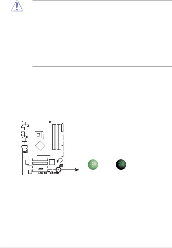
Onboard LED
The motherboard comes with a stand-by power LED. When lit, the green LED indicates that the system is ON, in sleep mode, or in soft-off mode, a reminder that you should shut down the system and unplug the power cable before removing or plugging in any motherboard component. The illustration below shows the location of the onboard LED.
|
SB_PWR |
|
P4P800-X |
|
|
|
ON |
OFF |
P4P800-X Onboard LED |
Standby |
Powered |
Power |
Off |
|
1-4 |
Chapter 1: Product introduction |
1.5Motherboard overview
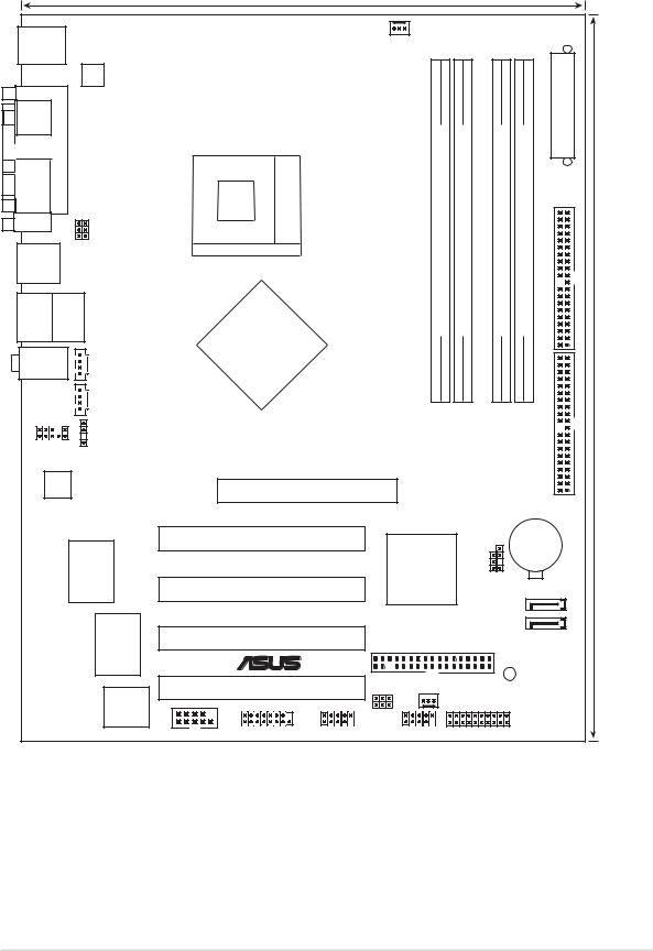
1.5.1 Motherboard layout
|
|
|
|
|
20.8cm (8.2in) |
|
|
|
|
|
|
|
PS/2KBMS |
|
|
|
|
|
CPU_FAN |
|
|
|
|
|
|
T: Mouse |
|
|
|
|
|
|
|
|
|
|
|
|
|
|
|
|
|
|
|
|
|
|
|
|
|
B: Keyboard |
|
|
|
|
|
|
|
|
|
|
Connector |
|
|
|
|
ATX12V |
|
|
|
|
|
|
|
|
|
SPDIF1 |
PORTPARALLEL |
USBPW34 |
USBPW12 |
|
478Socket |
|
module)pin-bit,184(64 |
module)pin-bit,184(64 |
module)pin-bit,184(64 |
module)pin-bit,184(64 |
IDEPRI |
PowerATX |
|
|
|
|
|
|
|
|
|
|
|
|
|
COM1 |
|
|
|
|
|
|
ADIMM1 |
ADIMM2 |
BDIMM1 |
BDIMM2 |
|
|
USB12 |
|
|
|
|
|
|
|
|||||
|
|
|
|
|
|
|
|
|
|
|
||
Bottom: |
Top: |
|
|
|
|
DDR |
DDR |
DDR |
DDR |
|
|
|
USB3 |
RJ-45 |
|
|
Intel |
|
|
|
|||||
USB4 |
|
|
OUT |
|
|
IDESEC |
(12.0in)30.5cm |
|||||
Top:Line In |
|
|
|
865PE |
|
|||||||
|
|
|
|
MCH |
|
|
|
|
|
|
|
|
Center:Line Out |
|
|
|
|
|
|
|
|
|
|
||
Below:Mic In |
|
CD |
|
|
|
|
|
|
|
|
|
|
|
|
|
|
|
|
|
|
|
|
|
|
|
|
|
|
AUX |
|
|
|
|
|
|
|
|
|
|
|
|
_ |
|
|
|
|
|
|
|
|
|
FP_AUDIO |
|
SPDIF |
|
|
|
|
|
|
|
|
|
|
AD1888 |
|
|
|
Accelerated Graphics Port (AGP) |
|
|
|
|
|
|||
|
|
|
|
|
|
|
|
|
|
|||
|
|
|
RTL8101L |
|
PCI1 |
|
|
|
CLRTC CHASSIS |
CR2032 3V |
|
|
|
|
|
|
|
|
|
|
|
Lithium Cell |
|
||
|
|
|
|
|
|
|
Intel |
|
|
CMOS Power |
||
|
|
|
|
|
|
|
|
|
|
|
|
|
|
|
|
|
|
PCI2 |
|
ICH5 |
|
|
|
|
|
|
|
|
|
|
|
|
|
|
|
|
|
|
|
|
|
|
P4P800-X |
|
|
|
SATA2 |
|
|
||
|
|
|
Super I/O |
|
|
|
SATA1 |
|
|
|||
|
|
|
|
PCI3 |
|
|
|
|
|
|||
|
|
|
|
|
FLOPPY |
|
|
|
|
|
||
|
|
|
|
|
|
|
|
|
|
|
||
|
|
|
|
|
|
|
|
|
|
|
|
|
|
|
|
|
|
|
® |
|
|
|
|
|
|
|
|
|
|
|
|
|
|
|
|
SB_PWR |
|
|
|
|
|
3Mb |
|
PCI4 |
|
|
|
|
|
|
|
|
|
|
|
|
|
CHA_FAN |
|
|
|
|
||
|
|
|
FWH |
|
|
|
USBPW56 |
|
|
|
|
|
|
|
|
|
|
GAME |
USB56 |
USBPW78 |
PANEL |
|
|
|
|
|
|
|
|
COM2 |
USB78 |
|
|
|
|
|||
|
|
|
|
|
|
|
|
|
|
|
|
|
ASUS P4P800-X motherboard |
|
|
|
|
|
|
1-5 |
|||||

1.5.2 Placement direction
When installing the motherboard, make sure that you place it into the chassis in the correct orientation. The edge with external ports goes to the rear part of the chassis as indicated in the image below.
1.5.3 Screw holes
Place seven (7) screws into the holes indicated by circles to secure the motherboard to the chassis.
Do not overtighten the screws! Doing so may damage the motherboard.
Place this side towards the rear of the chassis
1-6 |
Chapter 1: Product introduction |
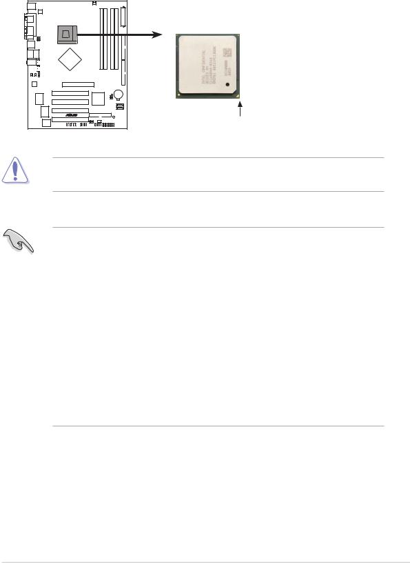
1.6Central Processing Unit (CPU)
1.6.1 Overview
The Intel® Pentium® 4 Northwood/Prescott processors has a gold triangular mark on one corner. This mark indicates the processor Pin 1 that should match a specific corner of the CPU socket.
P4P800-X
Gold Arrow
P4P800-X CPU Socket 478
Incorrect installation of the CPU into the socket may bend the pins and severely damage the CPU!
Notes on Intel® Hyper-Threading Technology
•This motherboard supports Intel® Pentium® 4 CPUs in the 478-pin package
with Hyper-Threading Technology.
•Hyper-Threading Technology is supported under Windows® XP/2003 Server and Linux 2.4.x (kernel) and later versions only. Under Linux, use the Hyper-Threading compiler to compile the code. If you are using any other operating systems, disable the Hyper-Threading Technology item in the BIOS to ensure system stability and performance.
•Installing the Windows® XP Service Pack 1 or later version is recommended.
•Make sure to enable the Hyper-Threading Technology item in BIOS before installing a supported operating system.
•For more information on Hyper-Threading Technology, visit www.intel.com/ info/hyperthreading.
To use the Hyper-Threading Technology on this motherboard:
1.Buy an Intel Pentium 4 CPU that supports Hyper-Threading Technology. Install the CPU.
2.Power up the system and enter BIOS Setup (see Chapter 2). Under the Advanced Menu, make sure that the item Hyper-Threading Technology is set to Enabled. The item appears only if you installed a CPU that supports HyperThreading Technology.
3.Reboot the computer.
ASUS P4P800-X motherboard |
1-7 |
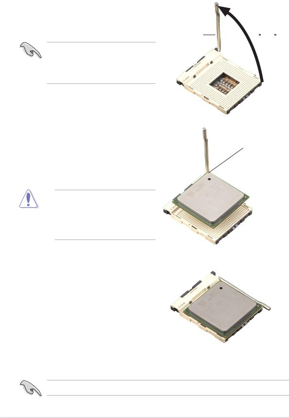
1.6.2 Installing the CPU
Follow these steps to install a CPU.
1.Locate the 478-pin ZIF socket on the motherboard.
2.Unlock the socket by pressing the lever sideways, then lift it up to a 90°- 100° angle.
Socket |
90 - 100 |
|
Make sure that the socket lever is lifted up to 90°-100° angle, otherwise the CPU does not fit in completely.
3. |
Position the CPU above the socket |
Gold Mark |
|
such that its marked corner matches |
|
|
the base of the socket lever. |
|
4. |
Carefully insert the CPU into the |
|
|
socket until it fits in place. |
|
The CPU fits only in one correct orientation. DO NOT force the CPU into the socket to prevent bending the pins and damaging the CPU!
5.When the CPU is in place, push down the socket lever to secure the CPU. The lever clicks on the side tab to indicate that it is locked.
6.Install a CPU heatsink and fan following the instructions that came with the heatsink package.
7.Connect the CPU fan cable to the CPU fan connector on the motherboard.
Connect the 4-pin ATX power connectors after you install the CPU.
1-8 |
Chapter 1: Product introduction |
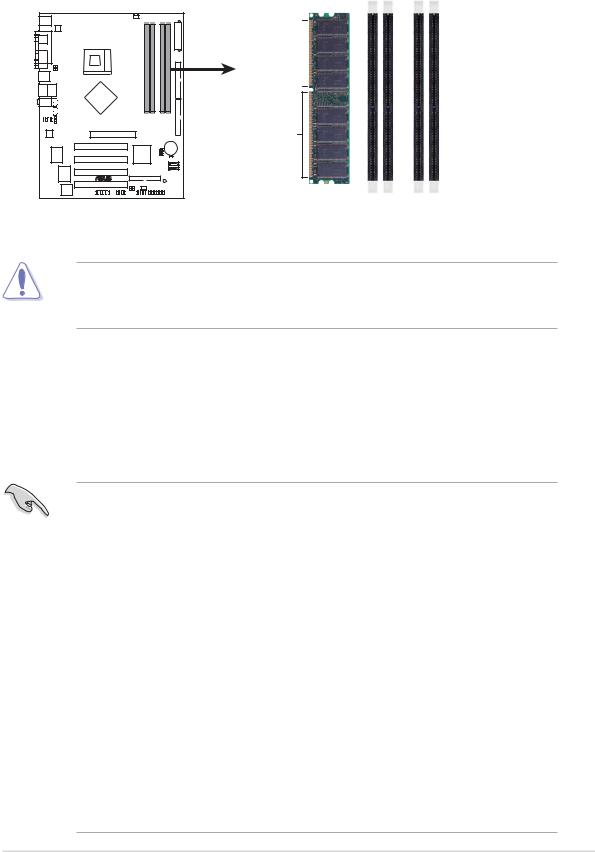
1.7System memory
1.7.1 DIMM sockets location
The following figure illustrates the location of the DDR DIMM sockets.
Pins80
Pins104
P4P800-X
P4P800-X 184-Pin DDR DIMM sockets
DIMM A1 |
DIMM A2 |
DIMM B1 |
DIMM B2 |
Make sure to unplug the power supply before adding or removing DIMMs or other system components. Failure to do so may cause severe damage to both the motherboard and the components.
1.7.2 Memory configurations
You may install 64MB, 128MB, 256MB, 512MB, and 1GB DDR DIMMs into the DIMM sockets using the memory configurations in this section.
Important notes
•Installing DDR DIMMs other than the recommended configurations may cause memory sizing error or system boot failure. Use any of the recommended configurations in Table 1.
•Use the blue DIMM slots first.
•In Dual-channel configurations, install only identical (the same type and size) DDR DIMM pairs for each channel.
•Always install DIMMs with the same CAS latency, otherwise, the system may run in a lower frequency. For optimum compatibility, it is recommended that you obtain memory modules from the same vendor. See list of Qualified Vendors List on page 1-10.
•When all four sockets are populated with 1GB DIMMs (Total 4 GB), the system may detect only 3+ GB (a little less than 4 GB) due to the SouthBridge resource allocation.
•Three DDR DIMMs installed into any three memory sockets will function in single channel mode.
•Make sure that the memory frequency matches the CPU FSB. Refer to Table 2 for configurations.
ASUS P4P800-X motherboard |
1-9 |

Table 1 |
Recommended memory configurations |
|
|
|||
|
|
|
|
|
|
|
|
|
|
Sockets |
|
|
|
Mode |
|
DIMM_A1 |
DIMM_A2 DIMM_B1 |
DIMM_B2 |
|
|
|
|
(blue) |
(black) |
(blue) |
(black) |
|
Single-channel |
(1) |
Populated |
— |
— |
— |
|
|
(2) |
— |
Populated |
— |
— |
|
|
(3) |
— |
— |
Populated |
— |
|
|
(4) |
— |
— |
— |
Populated |
|
Dual-channel |
(1) |
Populated |
— |
Populated |
— |
|
|
(2) |
— |
Populated |
— |
Populated |
|
|
(3) |
*Populated |
Populated |
Populated |
Populated |
|
|
|
|
|
|
|
|
*For dual-channel configuration (3), you may:
•install identical DIMMs in all four sockets
•install identical DIMM pair in DIMM_A1 and DIMM_B1 (blue sockets) and identical DIMM pair in DIMM_A2 and DIMM_B2 (black sockets)
•install same size DIMMs in DIMM_A1 and DIMM_B1 (blue sockets) and another same size pair in DIMM_A2 and DIMM_B2 (black sockets)
Table 2 Memory frequency/CPU FSB synchronization
This motherboard supports different memory frequencies depending on the CPU FSB (Front Side Bus) and the type of DDR DIMM.
CPU FSB |
DDR DIMM Type |
Memory Frequency |
|
|
|
800 MHz |
PC3200/PC2700/PC2100 |
400/320*/266 MHz |
|
|
|
533 MHz |
PC2700/PC2100 |
333/266 MHz |
|
|
|
400 MHz |
PC2100 |
266 MHz |
|
|
|
*When using 800 MHz FSB CPU, PC2700 DDR DIMMs run only at 320MHz (not 333MHz) due to chipset limitation.
DDR400 Qualified Vendor List (QVL)
|
|
|
|
|
|
DIMM support |
||
Size |
Vendor |
Model |
Brand |
Side(s) |
Component |
A |
B |
C |
|
|
|
|
|
|
|
|
|
256MB |
A DATA |
MDOAD5F3G31Y0D1E02 |
N/A |
SS |
ADD8608A8A-5B |
• |
• |
• |
|
|
|
|
|
|
|
|
|
256MB |
A DATA |
MDOHY6F3G31Y0N1E0Z |
Hynix |
SS |
HY5DU56822CT-D43 |
• |
• |
• |
256MB |
A DATA |
MDOSS6F3G31Y0K1E0Z |
SAMSUNG |
SS |
K4H560838E-TCCC |
• |
• |
• |
|
|
|
|
|
|
|
|
|
512MB |
A DATA |
MDOAD5F3H41Y0D1E02 |
N/A |
DS |
ADD8608A8A-5B |
• |
• |
• |
512MB |
A DATA |
MDOHY6F3H41Y0N1E0Z |
Hynix |
DS |
HY5DU56822CT-D43 |
• |
• |
• |
512MB |
A DATA |
MDOSS6F3H41Y0N1E0Z |
SAMSUNG |
DS |
K4H560838F-TCCC |
• |
• |
• |
512MB |
ATP |
AG64L64T8SQC4S |
SAMSUNG |
DS |
K4H560838D-TCC4 |
• |
• |
• |
(Continued on the next page)
1-10 |
Chapter 1: Product introduction |
DDR400 Qualified Vendor List (QVL)
|
|
|
|
|
|
DIMM support |
||
Size |
Vendor |
Model |
Brand |
Side(s) |
Component |
A |
B |
C |
|
|
|
|
|
|
|
|
|
256MB |
BRAIN POWER |
B6U808-256M-SAM-400 |
SAMSUNG |
SS |
K4H560838D-TCC4 |
• |
• |
• |
512MB |
BRAIN POWER |
B6U808-512M-SAM-400 |
SAMSUNG |
DS |
K4H560838D-TCC4 |
• |
• |
• |
256MB |
CENTURY |
DXV6S8MC5BC3U27E |
MICRON |
SS |
MT46V32M8TG-5BC |
• |
• |
• |
256MB |
CENTURY |
DXV6S8SSCCD3K27C |
SAMSUNG |
SS |
K4H560838D-TCCC |
• |
• |
• |
256MB |
CENTURY |
DXV6S8SSCCE3K27E |
SAMSUNG |
SS |
K4H560838E-TCCC |
• |
• |
• |
512MB |
CENTURY |
DXV2S8MC5BC3U27E |
MICRON |
DS |
MT46V32M8TG-5BC |
• |
• |
• |
512MB |
CENTURY |
DXV2S8SSCCD3K27C |
SAMSUNG |
DS |
K4H560838D-TCCC |
|
• |
• |
512MB |
CENTURY |
DXV2S8SSCCE3K27E |
SAMSUNG |
DS |
K4H560838E-TCCC |
• |
• |
• |
256MB |
CORSAIR |
CMX256A-3200C2PT |
Winbond |
SS |
W942508BH-5 |
• |
• |
• |
256MB |
CORSAIR |
VS256MB330308147 |
SAMSUNG |
SS |
K4H560838D-TCB3 |
• |
• |
• |
256MB |
CORSAIR |
VS256MB400 |
VALUE seLecT |
SS |
VS32M8-5 |
• |
• |
• |
512MB |
CORSAIR |
CMX512-3200C2 |
Winbond |
DS |
N/A |
• |
• |
• |
512MB |
CORSAIR |
VS512MB333 |
VALUE seLecT |
DS |
VS32M8-6 |
• |
• |
• |
|
|
|
|
|
|
|
|
|
512MB |
CORSAIR |
VS512MB400 |
VALUE seLecT |
DS |
VS32M8-5 |
• |
• |
• |
256MB |
elixir |
M2U25664DS88B3G-5T |
NANYA |
SS |
N2DS25680BT-5T |
• |
• |
• |
512MB |
elixir |
M2U25664DS8HB3G-5T |
NANYA |
DS |
N2DS25680BT-5T |
• |
• |
|
256MB |
GEIL |
GD3200-256V |
GEIL |
SS |
GLIL DDR 32M8 |
• |
• |
• |
512MB |
GEIL |
GD3200-512V |
GEIL |
DS |
GLIL DDR 32M8 |
• |
• |
|
512MB |
GEIL |
GE5123200B |
GEIL |
DS |
GL3LC32G88TG-5A |
• |
• |
|
128MB |
Hynix |
HYMD216646C(L)6-H |
Hynix |
SS |
HY5DU561622CT-H |
• |
|
|
256MB |
Hynix |
HYMD232726B(L)8-H |
Hynix |
SS |
HY5DU56822BT-H |
• |
• |
|
256MB |
Hynix |
HYMD232726B(L)8-J |
Hynix |
SS |
HY5DU56822BT-J |
• |
• |
|
256MB |
Infineon |
HYS64D32300GU-5-C |
Infineon |
SS |
HYB25D256800CE-5C |
• |
• |
• |
256MB |
Infineon |
HYS64D32300GU-6 |
Infineon |
SS |
HYB25D256800CE-6C |
• |
• |
• |
512MB |
Infineon |
HYS64D32300GU-5-B |
Infineon |
DS |
HYB25D256800CE-6C |
• |
• |
• |
|
|
|
|
|
|
|
|
|
512MB |
Infineon |
HYS64D64320GU-5-C |
Infineon |
DS |
HYB25D256800CE-6C |
• |
• |
• |
512MB |
Infineon |
HYS64D64320GU-6-C |
Infineon |
DS |
HYB25D256800CE-6C |
• |
|
|
|
|
|
|
|
|
|
|
|
256MB |
KINGSTON |
KVR400X64C3A/256 |
Hynix |
SS |
HY5DU56822BT-D43 |
• |
• |
• |
512MB |
KINGSTON |
KVR333X64C25/512 |
Hynix |
DS |
HY5DU56822BT-J |
• |
• |
• |
512MB |
KINGSTON |
KVR33X64C/256 |
Kingston |
DS |
03208DHIT-6 |
• |
|
|
512MB |
KINGSTON |
KVR400X64C3A/512 |
Hynix |
DS |
HY5DU56822BT-D43 |
• |
• |
• |
256MB |
Kreton |
N/A |
VT |
SS |
VT3225804T-5 |
• |
• |
• |
512MB |
Kreton |
N/A |
VT |
DS |
VT3225804T-5 |
• |
• |
|
256MB |
MICRON |
MT8VDDT3264AG-40BCB |
MICRON |
SS |
MT46V32M8TG-5BC |
• |
• |
|
512MB |
MICRON |
MT16VDDT6464AG-40BCB |
MICRON |
DS |
MT46V32M8TG-5BC |
• |
• |
• |
256MB |
PSC |
AL5D8B53T-5B1K |
PSC |
SS |
A2S56D30BTP |
• |
• |
• |
512MB |
PSC |
AL6D8A53T1-5B |
PSC |
DS |
A2S56D30ATP |
• |
|
|
512MB |
PSC |
AL6D8B53T-5B1K |
PSC |
DS |
A2S56D30BTP |
|
• |
|
256MB |
SAMSUNG |
M368L3223ETM-CCC |
SAMSUNG |
SS |
K4H560838E-TCCC |
• |
• |
• |
|
|
|
|
|
|
|
|
|
256MB |
SAMSUNG |
M368L3223ETM-CCC |
SAMSUNG |
SS |
K4H560838E-TCCC |
• |
• |
• |
256MB |
SAMSUNG |
M368L3223FTN-CCC |
SAMSUNG |
SS |
K4H560838F-TCCC |
• |
• |
|
|
|
|
|
|
|
|
|
|
256MB |
SAMSUNG |
M368L6423FTN-CB |
SAMSUNG |
DS |
K4H560939S-TCCC |
• |
• |
• |
512MB |
SAMSUNG |
M368L6423ETM-CCC |
SAMSUNG |
DS |
K4H560838E-TCCC |
• |
• |
• |
|
|
|
|
|
|
|
|
|
512MB |
SAMSUNG |
M368L6423FTN-CCC |
SAMSUNG |
DS |
K4H560838F-TCCC |
• |
• |
|
256MB |
Veritech |
VT400FMV/2561103 |
VT |
SS |
VT56DD32M8PC-5 |
• |
• |
• |
512MB |
Veritech |
VT400FMV/5121003 |
VT |
DS |
VT56DD32M8PC-5 |
• |
• |
|
Side(s): SS - Single Sided |
DS - Double Sided |
|
|
|
|
|
||
DIMM Support:
A- supports one module inserted into either slot, in a Single-channel memory configuration.
B- supports on pair of modules inserted into either the slots as one pair of Dual-channel memory configuration.
C- support for 4 modules inserted into all the slots as two pairs of Dual-channel memory configuration.
Obtain DDR DIMMs only from ASUS qualified vendors. Visit the ASUS website (www.asus.com) for the latest QVL.
ASUS P4P800-X motherboard |
1-11 |

1.7.3 Installing a DIMM
Follow these steps to install a DIMM.
1.Unlock a DIMM socket by pressing the retaining clips outward.
2.Align a DIMM on the socket such that the notch on the DIMM matches the break on the socket.
3.Firmly insert the DIMM into the socket until the retaining clips snap back in place and the DIMM is properly seated.
DDR DIMM
Unlocked
A DDR DIMM is keyed with a notch so that it fits in only one direction. DO NOT force a DIMM into a socket to avoid damaging the DIMM.
1-12 |
Chapter 1: Product introduction |
 Loading...