


P4BP-MX 2.0
User Guide
Motherboard

E1648
First Edition
June 2004
Copyright © 2004 ASUSTeK COMPUTER INC. All Rights Reserved.
No part of this manual, including the products and software described in it, may be reproduced, transmitted, transcribed, stored in a retrieval system, or translated into any language in any form or by any means, except documentation kept by the purchaser for backup purposes, without the express written permission of ASUSTeK COMPUTER INC. (“ASUS”).
Product warranty or service will not be extended if: (1) the product is repaired, modified or altered, unless such repair, modification of alteration is authorized in writing by ASUS; or (2) the serial number of the product is defaced or missing.
ASUS PROVIDES THIS MANUAL “AS IS” WITHOUT WARRANTY OF ANY KIND, EITHER EXPRESS OR IMPLIED, INCLUDING BUT NOT LIMITED TO THE IMPLIED WARRANTIES OR CONDITIONS OF MERCHANTABILITY OR FITNESS FOR A PARTICULAR PURPOSE. IN NO EVENT SHALL ASUS, ITS DIRECTORS, OFFICERS, EMPLOYEES OR AGENTS BE LIABLE FOR ANY INDIRECT, SPECIAL, INCIDENTAL, OR CONSEQUENTIAL DAMAGES (INCLUDING DAMAGES FOR LOSS OF PROFITS, LOSS OF BUSINESS, LOSS OF USE OR DATA, INTERRUPTION OF BUSINESS AND THE LIKE), EVEN IF ASUS HAS BEEN ADVISED OF THE POSSIBILITY OF SUCH DAMAGES ARISING FROM ANY DEFECT OR ERROR IN THIS MANUAL OR PRODUCT.
SPECIFICATIONS AND INFORMATION CONTAINED IN THIS MANUAL ARE FURNISHED FOR INFORMATIONAL USE ONLY, AND ARE SUBJECT TO CHANGE AT ANY TIME WITHOUT NOTICE, AND SHOULD NOT BE CONSTRUED AS A COMMITMENT BY ASUS. ASUS ASSUMES NO RESPONSIBILITY OR LIABILITY FOR ANY ERRORS OR INACCURACIES THAT MAY APPEAR IN THIS MANUAL, INCLUDING THE PRODUCTS AND SOFTWARE DESCRIBED IN IT.
Products and corporate names appearing in this manual may or may not be registered trademarks or copyrights of their respective companies, and are used only for identification or explanation and to the owners’ benefit, without intent to infringe.
ii

Contents
Notices ............................................................................................ |
v |
Safety information .......................................................................... |
vi |
About this guide ............................................................................. |
vii |
Conventions used in this guide ............................................ |
vii |
Typography........................................................................... |
vii |
P4BP-MX 2.0 specifications summary ......................................... |
viii |
Chapter |
1: Product introduction |
|
|
1.1 |
Welcome! ........................................................................... |
1-2 |
|
1.2 |
Package contents ............................................................... |
1-2 |
|
1.3 |
Special features.................................................................. |
1-3 |
|
|
1.3.1 |
Product Highlights .................................................. |
1-3 |
|
1.3.2 |
Unique ASUS features ........................................... |
1-4 |
1.4 |
Before you proceed ............................................................ |
1-5 |
|
1.5 |
Motherboard overview ........................................................ |
1-6 |
|
|
1.5.1 |
Motherboard layout ................................................ |
1-6 |
|
1.5.2 |
Placement direction ............................................... |
1-7 |
|
1.5.3 |
Screw holes ........................................................... |
1-7 |
1.6 |
Central Processing Unit (CPU)........................................... |
1-8 |
|
|
1.6.1 |
Overview ................................................................ |
1-8 |
|
1.6.2 |
Installing the CPU .................................................. |
1-9 |
1.7 |
System memory ............................................................... |
1-10 |
|
|
1.7.1 |
DIMM sockets location ......................................... |
1-10 |
|
1.7.2 |
Installing a DIMM ................................................. |
1-10 |
1.8 |
Expansion slots ................................................................. |
1-11 |
|
|
1.8.1 |
Standard interrupt assignments ............................ |
1-11 |
|
1.8.2 |
IRQ assignments for this motherboard ................. |
1-11 |
|
1.8.3 |
PCI slots .............................................................. |
1-12 |
1.9 |
Jumpers............................................................................ |
1-13 |
|
1.10 |
Connectors ....................................................................... |
1-15 |
|
|
1.10.1 |
Rear panel connectors ......................................... |
1-15 |
|
1.10.2 |
Internal connectors .............................................. |
1-16 |
iii

Contents
Chapter 2: BIOS information
2.1 |
Managing and updating your BIOS .................................... |
2-2 |
|
|
2.1.1 Creating a bootable floppy disk ............................. |
2-2 |
|
|
2.1.2 Updating the BIOS with EZ Flash feature .............. |
2-3 |
|
|
2.1.3 Recovering the BIOS with CrashFree BIOS .......... |
2-4 |
|
|
2.1.4 |
ASUS Update ........................................................ |
2-6 |
2.2 |
BIOS Setup program .......................................................... |
2-8 |
|
|
2.2.1 |
BIOS menu screen ................................................ |
2-9 |
|
2.2.2 |
Menu bar ................................................................ |
2-9 |
|
2.2.3 |
Legend bar ........................................................... |
2-10 |
|
2.2.4 |
General help ........................................................ |
2-10 |
|
2.2.5 |
Sub-menu ............................................................ |
2-10 |
|
2.2.6 |
Pop-up window .................................................... |
2-10 |
2.3 |
Main menu......................................................................... |
2-11 |
|
|
Primary and Secondary Master/Slave .............................. |
2-13 |
|
2.4 |
Advanced menu ............................................................... |
2-15 |
|
|
2.4.1 |
Advanced Chipset Features ................................ |
2-15 |
|
2.4.2 |
Chip Configuration ............................................... |
2-17 |
2.5 |
Power menu ..................................................................... |
2-20 |
|
|
Hardware Monitor ............................................................. |
2-22 |
|
2.6 |
Boot menu ........................................................................ |
2-23 |
|
2.7 |
Exit menu ......................................................................... |
2-24 |
|
Chapter 3: Software support
3.1 |
Install an operating system ................................................. |
3-2 |
|
3.2 |
Support CD information ...................................................... |
3-2 |
|
|
3.2.1 Running the support CD ........................................ |
3-2 |
|
|
3.2.2 |
Drivers menu ......................................................... |
3-3 |
|
3.2.3 |
Utilities menu ......................................................... |
3-3 |
|
3.2.4 |
ASUS Contact Information ..................................... |
3-4 |
3.3 |
Audio configuration............................................................. |
3-5 |
|
iv

Notices
Federal Communications Commission Statement
This device complies with Part 15 of the FCC Rules. Operation is subject to the following two conditions:
•This device may not cause harmful interference, and
•This device must accept any interference received including interference that may cause undesired operation.
The use of shielded cables for connection of the monitor to the graphics card is required to assure compliance with FCC regulations. Changes or modifications to this unit not expressly approved by the party responsible for compliance could void the user’s authority to operate this equipment.
Canadian Department of Communications Statement
This digital apparatus does not exceed the Class B limits for radio noise emissions from digital apparatus set out in the Radio Interference Regulations of the Canadian Department of Communications.
This class B digital apparatus complies with Canadian ICES-003.
Where to find more information
Refer to the following sources for additional information and for product and software updates.
1.ASUS Websites
The ASUS website provides updated information on ASUS hardware and software products. The ASUS websites are listed in the ASUS Contact Information on the inside front cover.
2.Optional Documentation
Your product package may include optional documentation, such as warranty flyers, that may have been added by your dealer. These documents are not part of the standard package.
v

Safety information
Electrical safety
•To prevent electrical shock hazard, disconnect the power cable from the electrical outlet before relocating the system.
•When adding or removing devices to or from the system, ensure that the power cables for the devices are unplugged before the signal cables are connected. If possible, disconnect all power cables from the existing system before you add a device.
•Before connecting or removing signal cables from the motherboard, ensure that all power cables are unplugged.
•Seek professional assistance before using an adpater or extension cord. These devices could interrupt the grounding circuit.
•Make sure that your power supply is set to the correct voltage in your area. If you are not sure about the voltage of the electrical outlet you are using, contact your local power company.
•If the power supply is broken, do not try to fix it by yourself. Contact a qualified service technician or your retailer.
Operation safety
•Before installing the motherboard and adding devices on it, carefully read all the manuals that came with the package.
•Before using the product, make sure all cables are correctly connected and the power cables are not damaged. If you detect any damage, contact your dealer immediately.
•To avoid short circuits, keep paper clips, screws, and staples away from connectors, slots, sockets and circuitry.
•Avoid dust, humidity, and temperature extremes. Do not place the product in any area where it may become wet.
•Place the product on a stable surface.
•If you encounter technical problems with the product, contact a qualified service technician or your retailer.
vi

About this guide
Conventions used in this guide
To make sure that you perform certain tasks properly, take note of the following symbols used throughout this manual.
WARNING: Information to prevent injury to yourself when trying to complete a task.
CAUTION: Information to prevent damage to the components when trying to complete a task.
IMPORTANT: Information that you MUST follow to complete a task.
NOTE: Tips and additional information to aid in completing a task.
Typography
|
Bold text |
Indicates a menu or an item to select. |
|
|
|
|
Italics |
Used to emphasize a word or a phrase. |
|
|
|
|
<Key> |
Keys enclosed in the less-than and greater-than sign |
|
|
indicates that you must press the enclosed key. |
|
|
Example: <Enter> indicates that you must press the |
|
|
Enter or Return key. |
|
|
|
|
<Multiple key names> |
If you must press two or more keys simultaneously, |
|
|
the key names are linked with a plus sign (+). |
|
|
Example: <Ctrl+Alt+D> |
|
|
|
|
Command |
Means that you must enter the command exactly as |
|
|
shown. Example: |
|
|
At the DOS prompt, type the command line: |
|
|
FORMAT A:/S |
|
|
|
vii

P4BP-MX 2.0 specifications summary
CPU |
Socket 478 for Intel® Pentium® 4 / Celeron® processors |
|
with speeds up to 3.06 GHz+ |
|
Supports Intel® Hyper-Threading Technology |
|
|
Chipset |
Northbridge: Intel® 845GV |
|
Southbridge: Intel® ICH4 (FW82801DB) |
|
|
Front System Bus |
533/400 MHz |
|
|
Memory |
2 x 184-pin DDR DIMM sockets for up to 2GB unbuffered |
|
non-ECC PC2700/2100 SDRAM memory |
|
|
Expansion slots |
3 x PCI slots |
|
|
Storage |
2 x UltraDMA 100/66 |
|
|
Audio |
Realtek® ALC655 6-channel CODEC |
|
Supports S/PDIF Out interface |
|
|
LAN |
Realtek® 8100C integrated 10/100Mbps LAN controller |
|
|
USB |
Maximum of six (6) USB 2.0 ports |
|
|
Special features |
ASUS JumperFree |
|
ASUS C.P.R. (CPU Parameter Recall) |
|
ASUS CrashFree BIOS |
|
ASUS EZ Flash |
|
ASUS MyLogo™ |
|
Power Loss Restart |
|
STR (Suspend-to-RAM) |
|
CPU Throttle |
|
|
Rear Panel I/O |
1 x Parallel port |
|
1 x Serial port |
|
1 x VGA port |
|
1 x PS/2 Keyboard port |
|
1 x PS/2 Mouse port |
|
4 x USB 2.0 ports |
|
1 x RJ-45 port |
|
Line In, Line Out, Mic ports |
|
|
Internal I/O |
CPU/Chassis fan connectors |
connectors |
20-pin ATX power connector |
|
4-pin auxiliary power connector |
|
1 x USB 2.0 header supports an additional 2 USB 2.0 ports |
|
Chassis intrusion connector |
|
IR connector |
|
S/PDIF Out connector |
|
IDE LED connector |
` |
Power LED connector |
|
Serial connector |
|
CD/AUX audio-in connectors |
|
Front panel audio connector |
|
|
|
(continued on the next page) |
viii

BIOS features |
3Mb Flash ROM, Award BIOS, TCAV, PnP, DMI2.0, WfM2.0, |
|
|
SM BIOS 2.3 |
|
Industry standard |
|
|
PCI 2.2, USB 2.0 |
|
|
Form Factor |
|
|
MicroATX form factor: 9.6 in x 8.6 in |
|
|
Support CD contents |
|
|
Device drivers |
|
|
|
ASUS PC Probe |
|
|
ASUS Live Update Utility |
|
|
Trend Micro™ PC-cillin™ anti-virus software |
|
|
|
|
* Specifications are subject to change without notice.
ix

x
Chapter 1
This chapter describes the features of the motherboard. It includes brief descriptions of the motherboard components, and illustrations of the layout, jumper settings, and connectors.
Product introduction

1.1Welcome!
Thank you for buying the ASUS® P4BP-MX 2.0 motherboard!
The motherboard delivers a host of new features and latest technologies making it another standout in the long line of ASUS quality motherboards!
The motherboard combines the powers of the Intel® Pentium® 4 processor and the Intel® 845GV chipset to set a new benchmark for an effective desktop platform solution.
Supporting up to 2GB of system memory with PC2700/PC2100 DDR SDRAM, high-resolution graphics via the Intel® Extreme Graphics, USB 2.0, and 6-channel audio features, the motherboard takes you ahead in the world of power computing!
Before you start installing the motherboard, and hardware devices on it, check the items in your package with the list below.
1.2Package contents
Check your motherboard package for the following items.
ASUS P4BP-MX 2.0 motherboard ASUS motherboard support CD 1 x IDE cable
1 x Floppy disk cable I/O shield
Bag of extra jumper caps User guide
If any of the above items is damaged or missing, contact your retailer.
1-2 |
Chapter 1: Product introduction |

1.3Special features
1.3.1 Product Highlights
Latest processor technology
The motherboard comes with a 478-pin surface mount, Zero Insertion Force (ZIF) socket for the Intel® Pentium® 4 processor in the 478-pin package with 512/256KB L2 cache on 0.13 or 0.09 micron process. This motherboard supports 533/400 MHz system front side bus that allows 4.3GB/s and 3.2GB/s data transfer rates, respectively. The motherboard also supports the Intel® Hyper-Threading Technology.
Onboard 10/100 LAN
The Realtek® 8100C PCI LAN controller provides easy implementation of 10/100 Mbps Fast Ethernet LAN.
Integrated Graphics
The Intel® 845GV chipset delivers realistic 3D/2D graphics with sharp images, fast rendering, smooth motion, and clearly defined details.
6 USB 2.0 ports
The motherboard implements the new Universal Serial Bus (USB) 2.0 specification, extending the connection speed from 12 Mbps on USB 1.1 to a fast 480 Mbps on USB 2.0 - supporting up to eight USB 2.0 ports. The higher bandwidth of USB 2.0 allows connection of devices such as high resolution video conferencing cameras, next generation scanners and printers, and fast storage units. USB 2.0 is backward compatible with USB 1.1.
6-Channel Audio solution
Onboard is the Realtek® ALC655 AC’97 CODEC. This CODEC provides high-quality 6-channel audio, S/PDIF out support and connector sensing function without having to buy advanced sound cards.
S/PDIF out
The motherboard supports S/PDIF-out function turns your computer into a high-end entertainment system with digital connectivity to powerful speaker systems.
ASUS P4BP-MX 2.0 motherboard |
1-3 |

1.3.2 Unique ASUS features
CrashFree BIOS
This feature allows you to restore the original BIOS data froma bootable floppy disk in case the BIOS codes and data are corrupted. This protection eliminates the need to buy a replacement ROM chip. See page 2-7.
ASUS EZ Flash BIOS
The ASUS EZ Flash feature works through the Award BIOS Update utility. With EZ Flash, you can easily update the system BIOS even before loading the operating system. See page 2-3.
ASUS MyLogo™
This new feature present in the motherboard allows you to personalize and add style to your system with customizable boot logos. See page 2-27.
C.P.R. (CPU Parameter Recall)
The C.P.R. feature of the motherboard BIOS allows automatic re-setting to the BIOS previous settings in case the system hangs due to overclocking. When the system hangs due to overclocking, C.P.R. eliminates the need to open the system chassis and clear the RTC data. Simply shut down and reboot the system, and BIOS automatically restores the CPU previous setting for each parameter.
1-4 |
Chapter 1: Product introduction |

1.4Before you proceed
Take note of the following precautions before you install motherboard components or change any motherboard settings.
1. Unplug the power cord from the wall socket before touching any component.
2.Use a grounded wrist strap or touch a safely grounded object or discharge any static electricity by touching the metal surface of the system chassis.
3.Hold components by the edges to avoid touching the ICs on them.
4.Whenever you uninstall any component, place it on a grounded antistatic pad or in the bag that came with the component.
5.Before you install or remove any component, ensure that the ATX power supply is switched off or the power cord is detached from the power supply. Failure to do so may cause severe damage to the motherboard, peripherals, and/or components.
Onboard LED
The motherboard comes with a stand-by power LED. When lit, this green LED indicates that the system is ON, in sleep mode, or in soft-off mode, a reminder that you should shut down the system and unplug the power cable before removing or plugging in any motherboard component. The illustration below shows the location of the onboard LED.
|
|
|
|
|
|
|
|
|
|
|
|
|
|
|
|
|
|
|
|
|
|
|
|
|
|
|
|
|
|
|
|
|
|
|
SB_PWR |
|
|
|
|
|
|
|
|
|
|
|
|
|
|
|
|
|
|
|
|
|
|
|
|
|
|
|
|
|
|
|
|
|
|
|
|
||
|
|
|
|
|
|
|
|
|
|
|
|
|
|
|
|
|
|
|
|
|
|
|
|
|
|
|
|
|
|
|
|
|
|
|
||
|
|
|
|
|
|
|
|
|
|
|
|
|
|
|
|
|
|
|
|
|
|
|
|
|
|
|
|
|
|
|
|
|
|
|
||
|
|
|
|
|
|
|
|
|
|
|
|
|
|
|
|
|
|
|
|
|
|
|
|
|
|
|
|
|
|
|
|
|
|
|
||
|
|
|
|
|
|
|
|
|
|
|
|
|
|
|
|
|
|
|
|
|
|
|
|
|
|
|
|
|
|
|
|
|
|
|
||
|
|
|
|
|
|
|
|
|
|
|
|
|
|
|
|
|
|
|
|
|
|
|
|
|
|
|
|
|
|
|
|
|
|
|
||
|
|
|
|
|
|
|
|
|
|
|
|
|
|
|
|
|
|
|
|
|
|
|
|
|
|
|
|
|
|
|
|
|
|
|
||
|
|
|
|
|
|
|
|
|
|
|
|
|
|
|
|
|
|
|
|
|
|
|
|
|
|
|
|
|
|
|
|
|
|
|
||
|
|
|
|
|
|
|
|
|
|
|
|
|
|
|
|
|
|
|
|
|
|
|
|
|
|
|
|
|
|
|
|
|
|
|
||
|
|
|
|
|
|
|
|
|
|
|
|
|
|
|
|
|
|
|
|
|
|
|
|
|
|
|
|
|
|
|
|
|
|
|
||
|
|
|
|
|
|
|
|
|
|
|
|
|
|
|
|
|
|
|
|
|
|
|
|
|
|
|
|
|
|
|
|
|
|
|
||
|
|
|
|
|
|
|
|
|
|
|
|
|
|
|
|
|
|
|
|
|
|
|
|
|
|
|
|
|
|
|
|
|
|
|
||
|
|
|
|
|
|
|
|
|
|
|
|
|
|
|
|
|
|
|
|
|
|
|
|
|
|
|
|
|
|
|
|
|
|
|
||
|
|
|
|
|
|
|
|
|
|
|
|
|
|
|
|
|
|
|
|
|
|
|
|
|
|
|
|
|
|
|
||||||
|
|
|
|
|
|
|
|
|
|
|
P4BP-MX 2.0 |
|
|
|
||||||||||||||||||||||
|
|
|
|
|
|
|
|
|
|
|
|
|
|
|
|
|
|
|
|
|
|
|
|
|
|
|
|
|
|
|
|
|
|
|
ON |
OFF |
|
|
|
|
|
|
|
|
|
|
|
|
|
|
|
|
|
|
|
|
|
|
|
|
|
|
|
|
|
|
|
|
|
|
|
||
|
|
|
|
|
|
|
|
|
|
|
|
|
|
|
|
|
|
|
|
|
|
|
|
|
|
|
|
|
|
|
|
|
|
|
||
|
|
|
|
|
|
|
|
|
|
|
|
|
|
|
|
|
|
|
|
|
|
|
|
|
|
|
|
|
|
|
|
|
|
|
||
|
|
|
|
|
|
|
|
|
|
|
|
|
|
|
|
|
|
|
|
|
|
|
|
|
|
|
|
|
|
|
|
|
|
|
Standby |
Powered |
|
|
P4BP-MX 2.0 Onboard LED |
||||||||||||||||||||||||||||||||||
|
|
Power |
Off |
|||||||||||||||||||||||||||||||||
ASUS P4BP-MX 2.0 motherboard |
1-5 |

1.5Motherboard overview
1.5.1 Motherboard layout
PS/2KBMS |
|
T: Mouse |
|
B: Keyboard |
|
COM1 |
|
PORT |
USBPWR 12 KBPWR |
PARALLEL |
|
VGA
|
|
|
|
|
|
|
|
USB12 |
|
|
|
|
|
|
|
|
|
|
|
|
|
|
|
|
|
|
|
|
Bottom: |
Top: |
_34 |
|||
|
USB34 |
RJ-45 |
USBPWR |
|||
|
|
|
||||
|
|
|
|
|
|
|
|
|
|
|
|
|
|
|
Top:Line In |
|
|
|
|
|
Center:Line Out
Below:Mic In


 FP_AUDIO
CPU_FAN
Socket 478
Intel 82845GV Memory
ATX12V1 Controller Hub
DDR DIMM1 (64/72 bit, 184-pin module)
0 1
DDR DIMM2 (64/72 bit, 184-pin module)
2 3
Super
I/O
 IR_CON
ATX Power Connector |
FLOPPY1 |
SEC IDE |
PRI IDE |
RTL8100C
Audio
Codec
SPDIF_OUT |
CD
PCI1 |
|
|
|
|
|
|
|
|
|
|
|
|
|
|
|
|
|
|
|
|
3Mbit Firmware Hub |
|
|
|
|
|
|
|
|
|
|
|
|
Intel |
|
||||||||||
|
|
|
|
|
|
|
|
|
|
|
|
|
||||||||||
P4BP-MX 2.0 |
|
|
|
|
|
|
|
|
|
|
|
|
|
|||||||||
|
|
|
|
|
|
|
|
|
|
|
|
|
||||||||||
|
|
|
|
|
|
|
|
|
|
|
82801DB |
|
|
|||||||||
PCI2 |
|
|
|
|
|
|
|
|
|
|
|
ICH4 |
|
|
||||||||
|
|
|
|
|
|
|
|
|
|
|
|
|
||||||||||
|
|
|
|
|
|
|
|
|
|
|
|
|
|
|
|
|
|
|
|
|
||
PCI3 |
|
|
|
|
|
|
|
|
|
|
|
|
|
|
|
|
|
|
|
CLRTC |
||
|
|
|
|
|
|
|
|
|
|
|
|
|
|
|
|
|
|
|
||||
|
|
|
|
|
|
|
|
|
|
|
|
|
|
|
|
|
|
|
||||
|
|
|
|
|
|
|
|
|
|
|
USBPWR_56 |
|||||||||||
|
CHA_FAN |
|
|
|
|
PLED |
AUX |
|
|
|
|
BUZZ |
|
SB_PWR |
COM2 |
USB56 |
GAME1 |
CHASSIS |
F_PANEL |
USBPWR_12 |
KBPWR |
|
USBPWR_34 |
|
USBPWR_56 |
|
CLRTC |
|
||||
|
3 |
|
3 |
|
3 |
1 |
2 |
2 |
3 |
1 2 |
2 |
3 |
2 |
2 |
|
2 |
2 |
|
|
|
|
|
|
|
|
2 |
2 |
|
|
|
|
|
|
|
||||
1 |
|
1 |
|
|
+5V |
+5VSB |
Clear CMOS |
Normal |
||||
+5V |
+5VSB |
1 |
|
+5V |
+5VSB |
|
||||||
+5V |
+5VSB |
(Default) |
|
|
|
(Default) |
||||||
(Default) |
|
(Default) |
|
|
|
|
|
|
||||
|
|
|
|
|
|
|
|
|
||||
(Default)
PLED1 |
F_PANEL |
||
1 |
Power LED |
Power Button |
|
|
|||
PLED+ NC PLED- |
PLED+ |
PLED- |
PWR GND |
|
IDE LED+ |
IDE LED- |
Ground Reset NC |
IDE_LED 
 Reset
Reset
1-6 |
Chapter 1: Product introduction |

1.5.2 Placement direction
When installing the motherboard, make sure that you place it into the chassis in the correct orientation. The edge with external ports goes to the rear part of the chassis as indicated in the image below.
1.5.3 Screw holes
Place six (6) screws into the holes indicated by circles to secure the motherboard to the chassis.
Do not overtighten the screws! Doing so may damage the motherboard.
Place this side towards the rear of the chassis
ASUS P4BP-MX 2.0 motherboard |
1-7 |

1.6Central Processing Unit (CPU)
1.6.1 Overview
The motherboard comes with a surface mount 478-pin Zero Insertion Force (ZIF) socket designed for the Intel® Pentium® 4 processor.
Take note of the marked corner (with gold triangle) on the CPU. This mark should match a specific corner on the socket to ensure correct installation.
 Gold Arrow
P4BP-MX 2.0
P4BP-MX 2.0 Socket 478
Incorrect installation of the CPU into the socket may bend the pins and severely damage the CPU!
Notes on Intel® Hyper-Threading Technology
1. This motherboard supports Intel® Pentium® 4 CPUs with Hyper-Threading Technology.
2.Hyper-Threading Technology is supported under Windows® XP and Linux 2.4.x (kernel) and later versions only. Under Linux, use the Hyper-Threading compliler to compile the code. If you are using any other operating systems, disable the Hyper-Threading Technology item in BIOS to ensure system stability and performance.
3.It is recommended that you install Windows® XP Service Pack 1.
4.Make sure to enable the Hyper-Threading Technology item in BIOS before installing a supported operating system.
5.For more information on Hyper-Threading Technology, visit www.intel.com/ info/hyperthreading.
1-8 |
Chapter 1: Product introduction |
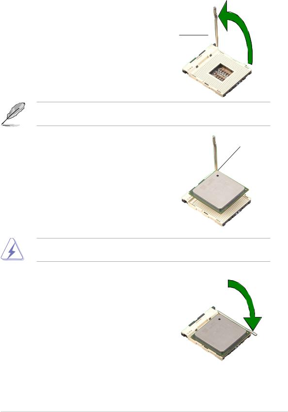
1.6.2 Installing the CPU
Follow these steps to install a CPU.
1. Locate the 478-pin ZIF socket on the motherboard.
90º~100º angle
2.Unlock the socket by pressing the lever sideways, then lift it up to a 90°- 100° angle.
Socket Lever
Make sure that the socket lever is lifted up to 90°-100° angle; otherwise, the CPU does not fit in completely.
3. |
Position the CPU above the socket |
Gold Mark |
|
such that its marked corner matches |
|
|
the base of the socket lever. |
|
4. |
Carefully insert the CPU into the |
|
|
socket until it fits in place. |
|
The CPU fits only in one correct orientation. DO NOT force the CPU into the socket to prevent bending the pins and damaging the CPU!
5.When the CPU is in place, push down the socket lever to secure the CPU. The lever clicks on the side tab to indicate that it is locked.
ASUS P4BP-MX 2.0 motherboard |
1-9 |
 Loading...