


P4S133-VM

Motherboard
®
P4S133-VM
User Guide

ii
Checklist
Copyright © 2002 ASUSTeK COMPUTER INC. All Rights Reserved.
No part of this manual, including the products and software described in it, may be reproduced,
transmitted, transcribed, stored in a retrieval system, or translated into any language in any
form or by any means, except documentation kept by the purchaser for backup purposes,
without the express written permission of ASUSTeK COMPUTER INC. (“ASUS”).
Product warranty or service will not be extended if: (1) the product is repaired, modified or
altered, unless such repair, modification of alteration is authorized in writing by ASUS; or (2)
the serial number of the product is defaced or missing.
Products and corporate names appearing in this manual may or may not be registered
trademarks or copyrights of their respective companies, and are used only for identification
or explanation and to the owners’ benefit, without intent to infringe.
The product name and revision number are both printed on the product itself. Manual revisions
are released for each product design represented by the digit before and after the period of
the manual revision number. Manual updates are represented by the third digit in the manual
revision number.
For previous or updated manuals, BIOS, drivers, or product release information, contact
ASUS at: http://www.asus.com or through any of the means indicated on the following page.
ASUS PROVIDES THIS MANUAL “AS IS” WITHOUT WARRANTY OF ANY KIND, EITHER EXPRESS
OR IMPLIED, INCLUDING BUT NOT LIMITED TO THE IMPLIED WARRANTIES OR CONDITIONS OF
MERCHANTABILITY OR FITNESS FOR A PARTICULAR PURPOSE. IN NO EVENT SHALL ASUS, ITS
DIRECTORS, OFFICERS, EMPLOYEES OR AGENTS BE LIABLE FOR ANY INDIRECT, SPECIAL,
INCIDENTAL, OR CONSEQUENTIAL DAMAGES (INCLUDING DAMAGES FOR LOSS OF PROFITS,
LOSS OF BUSINESS, LOSS OF USE OR DATA, INTERRUPTION OF BUSINESS AND THE LIKE),
EVEN IF ASUS HAS BEEN ADVISED OF THE POSSIBILITY OF SUCH DAMAGES ARISING FROM
ANY DEFECT OR ERROR IN THIS MANUAL OR PRODUCT.
SPECIFICATIONS AND INFORMATION CONTAINED IN THIS MANUAL ARE FURNISHED FOR
INFORMATIONAL USE ONLY, AND ARE SUBJECT TO CHANGE AT ANY TIME WITHOUT NOTICE,
AND SHOULD NOT BE CONSTRUED AS A COMMITMENT BY ASUS. ASUS ASSUMES NO
RESPONSIBILITY OR LIABILITY FOR ANY ERRORS OR INACCURACIES THAT MAY APPEAR IN
THIS MANUAL, INCLUDING THE PRODUCTS AND SOFTWARE DESCRIBED IN IT.
P4S133-VM
E983
March 2002
iii
Features
About this guide
This user manual contains complete information for installing the ASUS
P4S133-VM motherboard.
How this guide is organized
• Chapter 1: Product introduction. A summary of product features and
special attributes of new technologies.
• Chapter 2: Hardware information. A list of hardware setup procedures
and descriptions of all jumpers and connectors on the motherboard.
• Chapter 3: Powering up. Describes the power up sequence with
information on BIOS beep codes.
• Chapter 4: BIOS setup. How to change system settings using onboard
BIOS firmware. Detailed descriptions of the BIOS parameters are supplied.
• Chapter 5: Software support. A summary of contents on the
motherboard support CD ROM.
• Appendix and Glossary . Optional components and technical definitions.
• Index
Conventions used in this guide
T o make sure that you perform set-up tasks properly , take note of the following
symbols used throughout this manual.
WARNING! Information to prevent injury to yourself.
CAUTION! Information to prevent damage to the components.
IMPORTANT! Information that you MUST follow to complete a task.
NOTE! T ips and helpful information.

iv
Safeguards
Contents
About this guide .............................................................................. iii
How this guide is organized.................................................... iii
Conventions used in this guide............................................... iii
Safety information ...........................................................................vi
FCC/CDC statements .................................................................... vii
ASUS contact information ............................................................. viii
Chapter 1 Product introduction............................................... 1
Welcome!........................................................................................ 1
1.1 Package contents .................................................................. 1
1.2 Core Specifications ................................................................ 2
1.3 Special Features .................................................................... 3
1.4 Motherboard Components...................................................... 4
Chapter 2 Hardware information ............................................. 7
2.1 Motherboard installation ......................................................... 7
2.1.1 Placement direction ................................................... 7
2.1.2 Screw holes............................................................... 7
2.2 Motherboard layout ................................................................ 8
2.2.1 Layout contents ......................................................... 9
2.3 Before you proceed...............................................................10
2.4 Central Processing Unit (CPU)..............................................11
2.4.1 Overview .................................................................. 11
2.4.2 Installing the CPU .................................................... 12
2.4.3 Installing the heatsink and fan.................................. 14
2.4.4 Connecting the CPU fan cable................................. 16
2.5 System memory ....................................................................17
2.5.1 Overview ..................................................................17
2.5.2 General DIMM Notes ............................................... 17
2.5.3 Memory configurations ............................................ 18
2.5.4 Installing a DIMM ..................................................... 19
2.5.5 Removing a DIMM................................................... 20
2.6 Expansion slots.....................................................................21
2.6.1 Installing an expansion card..................................... 21
2.6.2 Configuring an expansion card ................................ 22
2.6.3 PCI slots ...................................................................23
2.6.4 AGP slot ...................................................................23
2.7 Jumpers ................................................................................24

v
Contents
2.8 Connectors ...........................................................................29
Chapter 3 Powering up .......................................................... 41
3.1 Starting up for the first time................................................... 41
3.2 Powering off the computer.................................................... 42
4.1 Managing and updating your BIOS....................................... 43
4.1.1 Using the computer system for the first time ............ 43
4.1.2 Updating BIOS procedures ...................................... 45
4.2 BIOS Setup program.............................................................47
4.2.1 BIOS menu bar.........................................................48
4.2.2 Legend bar ...............................................................48
4.3 Main menu ............................................................................50
4.3.1 Primary & Secondary Master/Slave ......................... 51
4.3.2 Keyboard Features .................................................. 55
4.4 Advanced Menu ....................................................................57
4.4.1 Chip Configuration ................................................... 59
4.4.2 I/O Device Configuration.......................................... 62
4.4.3 PCI Configuration .................................................... 64
4.5 Power Menu..........................................................................67
4.5.1 Power Up Control .................................................... 69
4.5.2 Hardware Monitor .................................................... 71
4.6 Boot Menu ............................................................................72
4.7 Exit Menu..............................................................................74
Chapter 5 Software support .................................................. 77
5.1 Install an operating system................................................... 77
5.2 Support CD information.........................................................77
5.3 P4S133-VM Motherboard Support CD ................................. 78
5.4 ASUS PC Probe....................................................................80
5.5 ASUS Live Update ................................................................85
5.6 3Deep Color Tuner................................................................86
5.7 ITE GSM Editor.....................................................................88
Glossary .................................................................................. 93
Index ........................................................................................ 97

vi
Safety information
Electrical safety
• To prevent electrical shock hazard, disconnect the power cable from the
electrical outlet before relocating the system.
• When adding or removing devices to or from the system, ensure that the
power cables for the devices are unplugged before the signal cables are
connected. Disconnect all power cables from the existing system before
you add a device.
• Before connecting or removing signal cables from the motherboard, ensure
that all power cables are unplugged.
• Seek professional assistance before using an adpater or extension cord.
These devices could interrupt the grounding circuit.
• Make sure that your power supply is set to the voltage available in your
area.
• If the power supply is broken, contact a qualified service technician or your
retailer.
Operational safety
• Before installing the motherboard and adding new devices, carefully read
all the manuals that came with the package.
• Before use ensure all cables are correctly connected and the power cables
are not damaged. If you detect any damage, contact the dealer immediately .
• To avoid short circuits, keep paper clips, screws, and staples away from
connectors, slots, sockets and circuitry.
• Avoid dust, humidity, and temperature extremes. Do not place the product
in any area where it may become wet.
• Mount the motherboard inside a standard PC enclosure.
• If you encounter technical problems with the product, contact a qualified
service technician or the dealer.

vii
FCC/CDC statements
Federal Communications Commission Statement
This device complies with FCC Rules Part 15. Operation is subject to the
following two conditions:
• This device may not cause harmful interference, and
• This device must accept any interference received including interference
that may cause undesired operation.
This equipment has been tested and found to comply with the limits for a
Class B digital device, pursuant to Part 15 of the FCC Rules. These limits
are designed to provide reasonable protection against harmful interference
in a residential installation. This equipment generates, uses and can radiate
radio frequency energy and, if not installed and used in accordance with
manufacturer’s instructions, may cause harmful interference to radio
communications. However, there is no guarantee that interference will not
occur in a particular installation. If this equipment does cause harmful
interference to radio or television reception, which can be determined by
turning the equipment off and on, the user is encouraged to try to correct the
interference by one or more of the following measures:
• Reorient or relocate the receiving antenna.
• Increase the separation between the equipment and receiver.
• Connect the equipment to an outlet on a circuit different from that to
which the receiver is connected.
• Consult the dealer or an experienced radio/TV technician for help.
The use of shielded cables for connection of the monitor to the
graphics card is required to assure compliance with FCC regulations.
Changes or modifications to this unit not expressly approved by the
party responsible for compliance could void the user’s authority to
operate this equipment.
Canadian Department of Communications Statement
This digital apparatus does not exceed the Class B limits for radio noise
emissions from digital apparatus set out in the Radio Interference
Regulations of the Canadian Department of Communications.
This class B digital apparatus complies with Canadian ICES-003.

viii
ASUS contact information
ASUSTeK COMPUTER INC. (Asia-Pacific)
Marketing
Address: 150 Li-Te Road, Peitou, Taipei, Taiwan 112
Telephone: +886-2-2894-3447
Fax: +886-2-2894-3449
Email: info@asus.com.tw
Technical Support
Tel (English): +886-2-2890-7123
Tel (Chinese): +886-2-2890-7113
Fax: +886-2-2890-7698
Email: tsd@asus.com.tw
Newsgroup: cscnews.asus.com.tw
WWW: www.asus.com.tw
FTP: ftp.asus.com.tw/pub/ASUS
ASUS COMPUTER INTERNATIONAL (America)
Marketing
Address: 6737 Mowry Avenue, Mowry Business Center, Building 2
Newark, CA 94560, USA
Fax: +1-510-608-4555
Email: info-usa@asus.com.tw
Technical Support
Fax: +1-510-608-4555
BBS: +1-510-739-3774
Email: tsd@asus.com
WWW: www.asus.com
FTP: ftp.asus.com/pub/ASUS
ASUS COMPUTER GmbH (Europe)
Marketing
Address: Harkortstr. 25, 40880 Ratingen, BRD, Germany
Fax: +49-2102-442066
Email: sales@asuscom.de (for marketing requests only)
Technical Support
Hotline: MB/Others: +49-2102-9599-0
Notebook: +49-2102-9599-10
Fax: +49-2102-9599-11
Support (Email): www.asuscom.de/de/support (for online support)
WWW: www.asuscom.de
FTP: ftp.asuscom.de/pub/ASUSCOM
Chapter 1
Product introduction

ASUS P4S133-VM motherboard

ASUS P4S133-VM motherboard user guide
1
Welcome!
Thank you for buying the ASUS
®
P4S133-VM motherboard!
The ASUS
P4S133-VM motherboard delivers a host of new features to
ensure long-lasting, superlative performance. The ASUS
®
P4S133-VM
motherboard is the prime choice for home PCs and workstations.
The P4S133-VM incorporates the Intel
®
Pentium
®
4 Processor coupled
with the SiS 650 chipset to set a new benchmark for an effective desktop
platform solution.
~ CPU Thermal Protection
~ Up to 2GB of system memory of PC100/133 SDRAM
~ High-resolution graphics via an AGP 4X slot
~ Digital Audio Interface for 3D sound
~ LAN Controller onboard
~ Two USB ports plus two headers for four more
Before installing the motherboard, check the items in your package:
1.1 Package contents
Check your P4S133-VM package for the following items.
ASUS P4S133-VM motherboard (Flex ATX form factor: 9.6-in x 7.5-in)
ASUS P4S133-VM support CD
ASUS 2-port USB 1.1 module
80-conductor ribbon cable for UltraDMA/33/66/100 IDE drives
40-conductor IDE cable
Ribbon cable for a 3.5-inch floppy drive
Bag of extra jumper caps
User Guide
If any of the above items is damaged or missing, contact your retailer.

2
Chapter 1: Product introduction
1.2
Core Specifications
The P4S133-VM motherboard is designed and assembled according to the
highest standards. This ASUS motherboard represents the latest advances
and offers users the finest componentry available today...
Latest P4 Processor Technology: Intel Pentium 4 Socket 478 Northwood
Processor. The Pentium 4 processor utilizes the advanced 0.18 micron
processor core in FC-PGA2 package for a 2.0GHz frequency, while the
Northwood processor uses the 0.13 micron processor core with 512KB
L2 cache for up to a speedy 2.2+ GHz frequency . The P4 offers optimized
performance for audio, video, and Internet applications.
North Bridge Chipset: the SiS
®
650 supports AGP 4X/2X mode, 100MHz
Front Side Bus, and the fastest 266/200MHz memory bus.
Integrated 4X graphics SiS315.
South Bridge Chipset: the SiS
®
961 integrated peripheral controller supports
UltraDMA/100/66/33 for burst mode data transfer rates of up to 100MB/
sec, and USB controller with two root hubs for six USB ports.
PC133 SDRAM: Equipped with two Dual Inline Memory Module (DIMM)
sockets to support Intel PC133-compliant (8, 16, 32, 64, 128, 256, or
512MB) SDRAM up to 2GB.
UltraDMA/100 Support: Comes with an onboard PCI Bus Master IDE
controller with two connectors that support four IDE devices on two
channels. Supports UltraDMA100/66/33, PIO Modes 3 & 4, Bus Master
IDE DMA Mode 2, and Enhanced IDE devices, such as DVD-ROM, CD-
ROM, CD-R/RW, LS-120, and Tape Backup drives.
Multi-I/O Chipset: Offers complete support for a variety of I/O functions.
Provides one high-speed UART compatible serial ports and one parallel
port with EPP and ECP capabilities. UART2 can also be directed to
support a smart card, or the Infrared Module for wireless connections.
The Super I/O controller supports a floppy disk drive.
Smart BIOS: 2Mb firmware enables Vcore and CPU/DDR SDRAM frequency
adjustments, boot block write protection, and HD/SCSI/MO/ZIP/CD/Floppy
boot selection.
Concurrent PCI: Concurrent PCI allows multiple PCI transfers from PCI
master busses to the memory and processor.
Expansion: One AGP 4X, four USB ports, three PCI slots, SPDIF digital
audio, front audio panel, smart card, infrared.
Connections: Parallel, PS/2 mouse, PS/2 keyboard, 2 USB, RJ45 (optional),
Microphone, Line-In Jack, Line-Out Jack, Standard ATX power.

ASUS P4S133-VM motherboard user guide
3
1.3 Special Features
Easy Overclocking
• Quickly adjust CPU frequency multiples with BIOS in JumperFree
™
Mode
• Adjustable FSB/MEM/PCI frequency ratio
• Stepless Frequency Selection (SFS) for fine-tuning system bus frequency
from at 1MHz increments
• Optimal system performance available with BIOS built-in Turbo Mode
Digital Audio: On audio models, a digital audio AC’97 CODEC and a special
connector is available onboard to accommodate the Sony/Philips Digital
Interface (S/PDIF) Output module, which supports coaxial and fiber
interfaces. Experience 5.1-channel surround sound and enhanced 3D
audio while playing DVDs and computer games.
Smart Card Reader Support: A special connector for the Smart Card Reader
comes onboard to support the cutting-edge technology for increased
security in authenticating online transactions, editing IC-based information.
T emperature, Fan and V oltage Monitoring: CPU temperature is monitored
by the ASUS ASIC through the CPU’s internal thermal diode to prevent
overheating and damage. All system fans are monitored for RPM and
failure. System voltage levels are monitored to ensure stable voltage to
critical motherboard components.
ACPI Ready: Advanced Configuration Power Interface (ACPI) provides more
Energy Saving Features for operating systems that support OS Direct
Power Management (OSPM).
Onboard LAN (Optional): The motherboard incorporates the PHY ICS1893Y
chip to support 10BASE-T/100BASE-TX Fast Ethernet networking.
Auto Fan Off: The system fans powers off automatically even in sleep mode.
Dual Function Power Button: Push the power button for less than 4 seconds
when the system is operating places the system into sleep or soft-off
modes, depending on the BIOS or OS setting. If the power button is
pressed for more than 4 seconds, the system enters the soft-off mode
regardless of the BIOS setting.

4
Chapter 1: Product introduction
Location
Processor Support Socket 478 for Intel
®
P4
™
Processors .............................2
Chipsets SiS
®
650 North Bridge .....................................................3
SiS
®
961 South Bridge ....................................................7
2Mbit Programmable Flash EEPROM ..........................16
Multi-I/O Controller ........................................................ 17
Audio Controller ............................................................20
Main Memory 2 SDRAM DIMM Sockets (2GB) ..................................... 5
Expansion Slots 3 PCI Slots .................................................................... 18
1 Accelerated Graphics Port (AGP) 4X Slot .................. 21
System I/O 1 Floppy Disk Drive Connector .....................................14
2 IDE Connectors (UltraDMA/100 Support) .................... 6
Smart Card Connector .................................................. 15
1 Infrared Connector ..................................................... 13
1 System Panel Connector ...........................................10
USB Headers (USB2, USB3) ........................................ 11
Modem Connector.........................................................23
1 Parallel Port................................................................26
1 Serial Port (COM1).....................................................32
1 VGA Connector .......................................................... 31
USB Connectors (Port 0/1 & 2/3) ................................. 33
1 PS/2 Mouse Connector .................................(green) 24
1 PS/2 Keyboard Connector .......................... (purple) 34
Hardware Monitoring System Voltage Monitor (integrated in ASUS ASIC) .......8
Special Feature Onboard LED ................................................................12
Network Feature 1 RJ45 Connector (Optional) ........................................25
Audio Features (on audio models only)
SPDIF-out Connector ...................................................... 9
Front Panel Audio Connector ........................................ 19
Audio Controller Chipset ............................................... 20
Audio Connectors..........................................................22
1 Line Out Connector ......................................... (lime) 30
1 Line In Connector ................................... (light blue) 29
1 Microphone Connector .................................... (pink) 28
Power ATX Power Supply Connector ......................................... 4
ATX 12V Power Supply Connector .................................1
Form Factor MicroATX
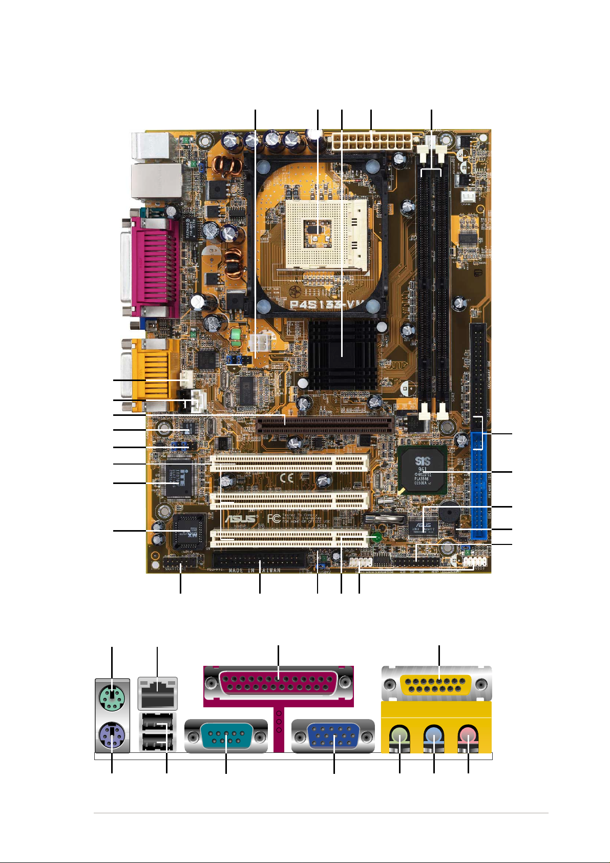
1.4
Motherboard Components
Before installing the P4S133-VM motherboard, take time to familiarize yourself
with its configuration: understanding the motherboard makes upgrading easy .
Sufficient knowledge of specifications prevents accidental damage.
ASUS P4S133-VM motherboard user guide
5
1.4.1 Component Locations
23 4 5
21
14
18
17
1
16
19
23
1215
22
11
6
7
9
20
8
10
13
24 25 26 27
28
29303234 33 31

Chapter 2
Hardware information

ASUS P4S133-VM motherboard
ASUS P4S133-VM motherboard user guide
7
2.1 Motherboard installation
Before you install the motherboard, study the configuration of your chassis
to ensure that the motherboard fits into it. The P4S133-VM uses the ATX
form factor that measures 24.5cm (9.6 in.) x 19.1 cm (7.5 in.), a standard
fit for most chassis.
Do not overtighten the screws! Doing so may damage the
motherboard.
2.1.1 Placement direction
When installing the motherboard, make sure that you place it into the
chassis in the correct orientation. The edge with external ports goes to the
rear part of the chassis. Refer to the image below.
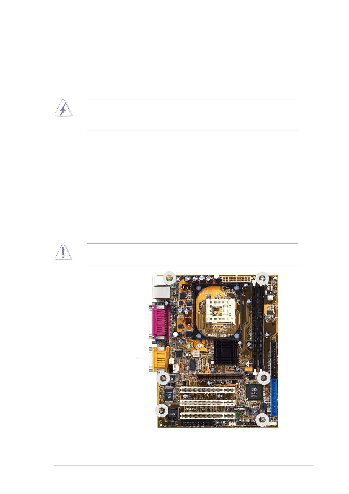
2.1.2 Screw holes
Place six (6) screws into the holes indicated by circles to secure the
motherboard to the chassis.
Make sure to unplug the power cord before installing or removing the
motherboard. Failure to do so may cause you physical injury and
damage motherboard components.
Place this side towards
the rear of the chassis
8
Chapter 2: Hardware information
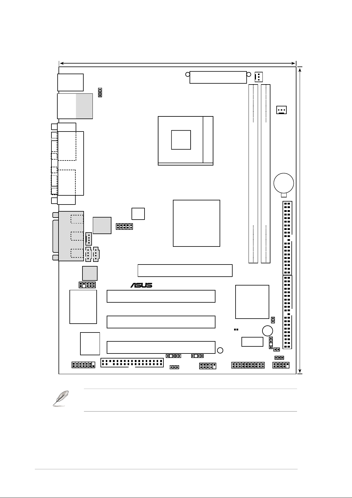
2.2 Motherboard layout
The audio and LAN features are optional. These components are
grayed out in the above motherboard layout.
FLOPPY1
HPANEL1
IR1
CD1
CPUFAN1
SiS650
HOST/
Memory
Controller
PS/2
T: Mouse
B: Keyboard
GAME_AUDIO
Mic
In
Line
Out
Line
In
AUX1
IDELED1
USB2
USBV2
P4S133-VM
®
SMARTCON1
FPAUDIO1
MODEM
ITE 8707F
Super I/O
2Mbit
Flash
BIOS
PCI Slot 1
ATX Power Connector
Primary IDE
Secondary IDE
Bottom:
USB1
USB2
Top:
RJ-45
2 3
0 1
Accelerated Graphics Port
(AGP)
USBV1
SiS961
MuTLOL
Media
I/0
SPDIF1
ATX12V1
Audio
Codec
ICS
1893Y
ASUS
Mozart
CHASFAN1
CLRRTC1
19.1cm (7.5in)
24.4cm (9.6in)
Socket 478
PCI Slot 2
PCI Slot 3
COM1
PARALLEL PORT
VGA
CHAS_IN1
USB3
USBV3
DIMM Socket 1 (72-bit, 168-pin module)
DIMM Socket 2 (72-bit, 168-pin module)
CR2032 3V
Lithium Cell
CMOS Power
JF1
FSJ1
LED1
BUZZER

ASUS P4S133-VM motherboard user guide
9
2.2.1 Layout contents
CPU, Memory and Expansion Slots
1) Socket 478 p. 12 Installing the CPU
2) Heatsink p. 14 Installing the Heatsink and Fan
3) Memory p. 17System Memory Support
4) PCI 1/2/3 p. 21 32-bit PCI Bus Expansion Slots
5) AGP 4x p. 23 Accelerated Graphics Slot
Motherboard Settings (Switches and Jumpers)
1) JF1 p. 24 JumperFree Mode Setting (Disable/Enable)
2) FSJ1 p. 25 Frequency Selection
(Jumpers 1–5)
3)
USBV1, 2, 3
p. 26 USB Device Wake-up (+5V / +5VSB)
4) CLRRTC1 p. 27 Clear RTC RAM
Connectors
1) PS2KBMS p. 29 PS/2 Mouse Port (6 pin female)
2) PS2KBMS p. 29 PS/2 Keyboard Port (6 pin female)
3) USB p. 30 U
niversal Serial Bus Ports 0, 1, 2 & 3 (Two x 4 pin female)
4) PRINTER p. 30 Parallel Port (25 pin female)
5) COM1 p. 30 Serial Port (9 pin male)
6) GAME_AUDIO p. 31 Game/MIDI Ports (Gold 15 pin)
7) AUDIO p. 31 Audio Connectors (Three 1/8” AUDIO)
8) RJ45 p. 31 Fast-Ethernet Port Connector (4 pin female)
9) IDELED p. 32 IDE Activity LED (Two 40-1 pin)
10) PRIMARY / SEC. IDE p. 33 IDE Connectors (Four 4 0-1 pin)
11) FLOPPY p. 34 Floppy Disk Drive Connector (34-1 pin)
12)
CPUFAN1, CHAFAN1
p. 34
CPU and Chassis Fan Connectors (Two 3 pin)
13) ATXPWR p. 35 ATX Power Supply Connector (20 pin)
14) USB2/3 p. 36 USB Headers (Two 10-1 pin)
15) CD / AUX / MODEM p. 36 Internal Audio Connectors
(Three 4-1 pin) (optional)
16) FPAUDIO1 p. 37 ASUS Front Panel Audio Connector (24-1 pin)
17) SPDIF1 p. 37 Digital Audio Connector (4-1 pin)
18) CHASSIS p. 38 Chassis Open Alarm Lead (4-1 pin)
19) IR1 p. 39 Infrared module connector (5-1 pin)
20) SMARTCARD p. 39 Smart Card Reader Connector (14-1 pin)
21) PLED p. 40 System Power LED Lead (3-1 pin)
22) SPEAKER p. 40 System Warning Speaker Lead (4 pin)
23) MLED p. 40 System Message LED Lead (2 pin)
24) SMI p. 40 System Management Interrupt Lead (2 pin)
25) PWRSW p. 40 ATX Power Switch / Soft-Off Switch Lead (2 pin)
26) RESET p. 40 Reset Switch Lead (2-pin)

10
Chapter 2: Hardware information
2.3 Before you proceed
Take note of the following precautions before you install motherboard
components or change any motherboard settings.
1. Unplug the power cord from the wall socket before touching
any component.
2. Use a grounded wrist strap or touch a safely grounded object
or to a metal object, such as the power supply case, before handling
components to avoid damaging them due to static electricity.
3. Hold components by the edges and do not to touch the ICs on
them.
4. Whenever you uninstall any component, place it on a grounded
antistatic pad or in the bag that came with the component.
5. Before you install or remove any component, ensure that
the ATX power supply is switched off or the power cord is
detached from the power supply. Failure to do so may cause
severe damage to the motherboard, peripherals, and/or
components.
ASUS P4S133-VM motherboard user guide
11
2.4 Central Processing Unit (CPU)
2.4.1 Overview
The motherboard comes with a surface mount 478-pin Zero Insertion
Force (ZIF) socket. This socket is specifically designed for the Intel
®
Pentium
®
4 478/Northwood Processor.
The Intel Pentium 4 Processor in the 478-pin package uses the Flip-Chip
Pin Grid Array 2 (FC-PGA2) package technology, and includes the Intel
®
NetBurst™ micro-architecture. The Intel NetBurst micro-architecture
features the hyper-pipelined technology, rapid execution engine, 400MHz
system bus, and execution trace cache. Together, these attributes improve
system performance by allowing higher processor frequencies, faster
execution of integer instructions, and a data transfer rate of 3.2GB/s.
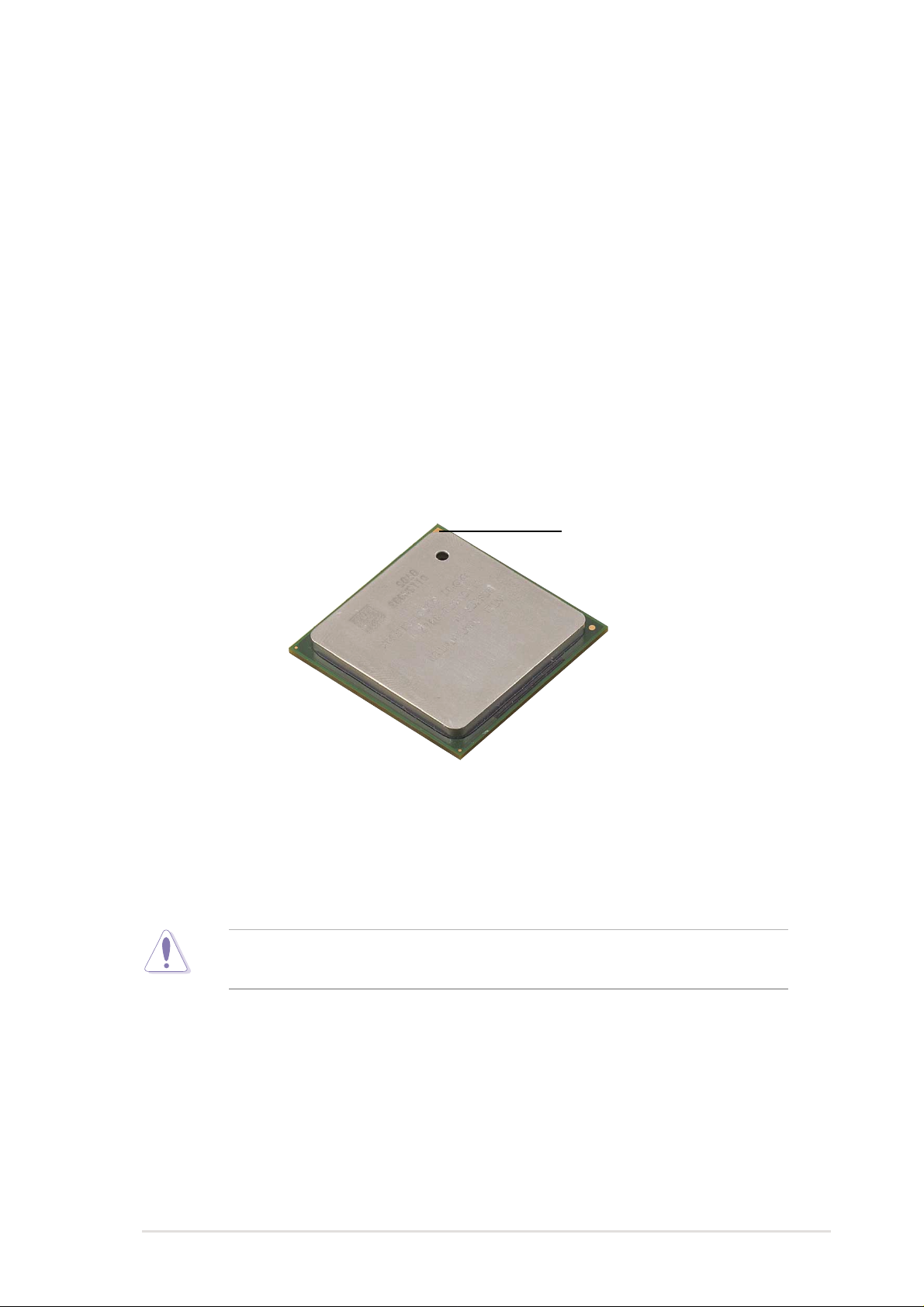
Note in the illustration that the CPU has a gold triangular mark on one
corner. This mark indicates the processor Pin 1 that should match a
specific corner of the CPU socket.
Incorrect installation of the CPU into the socket may bend the pins and
severely damage the CPU!
Gold Mark
12
Chapter 2: Hardware information
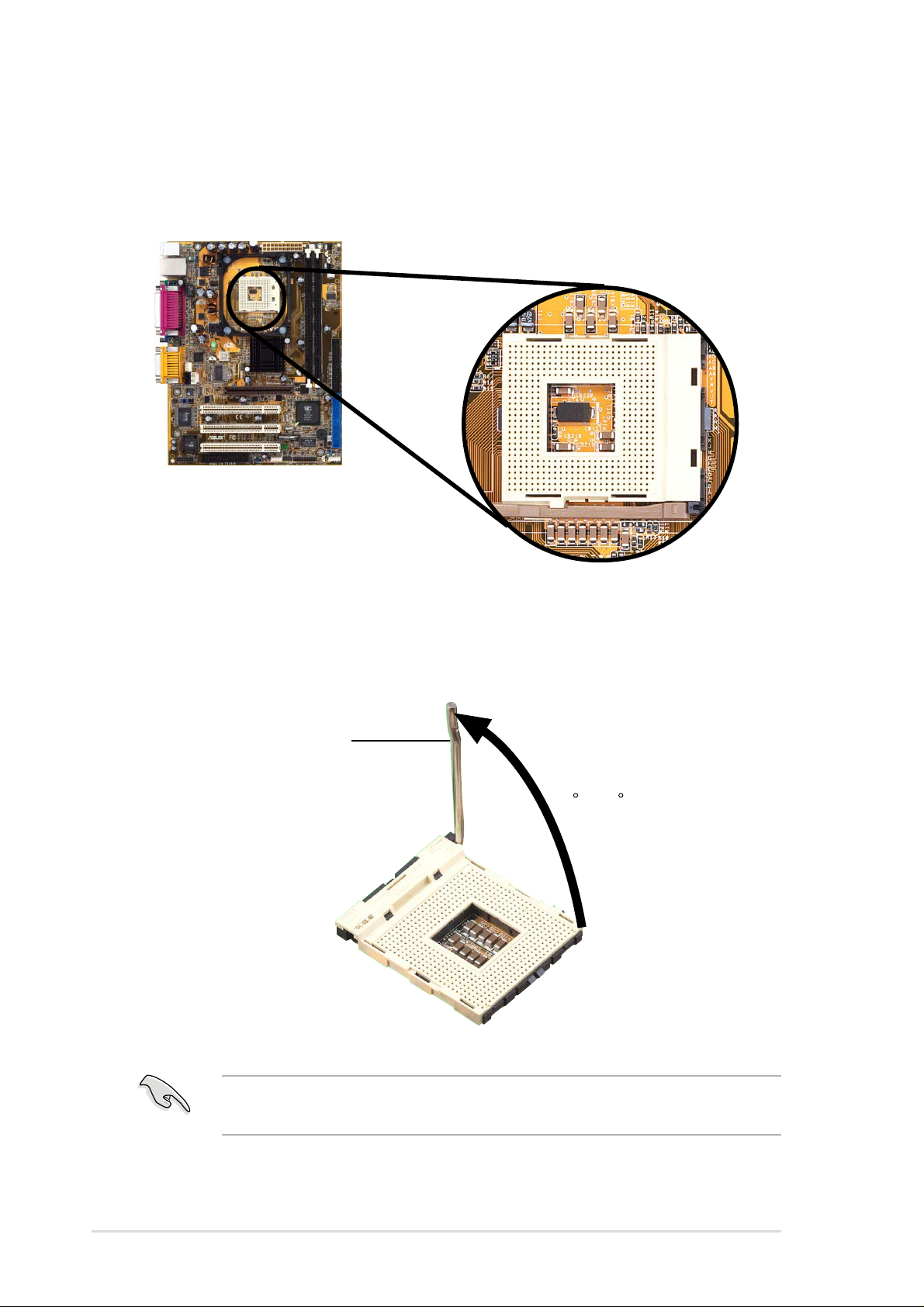
2.4.2 Installing the CPU
Follow these steps to install a CPU.
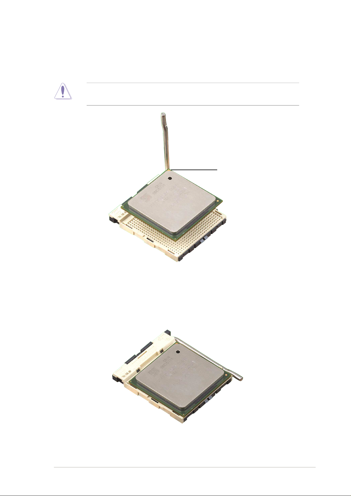
1. Locate the 478-pin ZIF socket on the motherboard.
2. Unlock the socket by pressing the lever sideways, then lift it up to a
90°-100° angle.
Make sure that the socket lever is lifted up to 90°-100° angle,
otherwise the CPU does not fit in completely.
Socket Lever
90 -100
ASUS P4S133-VM motherboard user guide
13
3. Position the CPU above the socket such that its marked corner
matches the base of the socket lever.
4. Carefully insert the CPU into the socket until it fits in place.
The CPU fits only in one correct orientation. DO NOT force the CPU
into the socket to prevent bending the pins and damaging the CPU!
5. When the CPU is in place, press it firmly on the socket while you push
down the socket lever to secure the CPU. The lever clicks on the side
tab to indicate that it is locked.
Gold Mark
14
Chapter 2: Hardware information
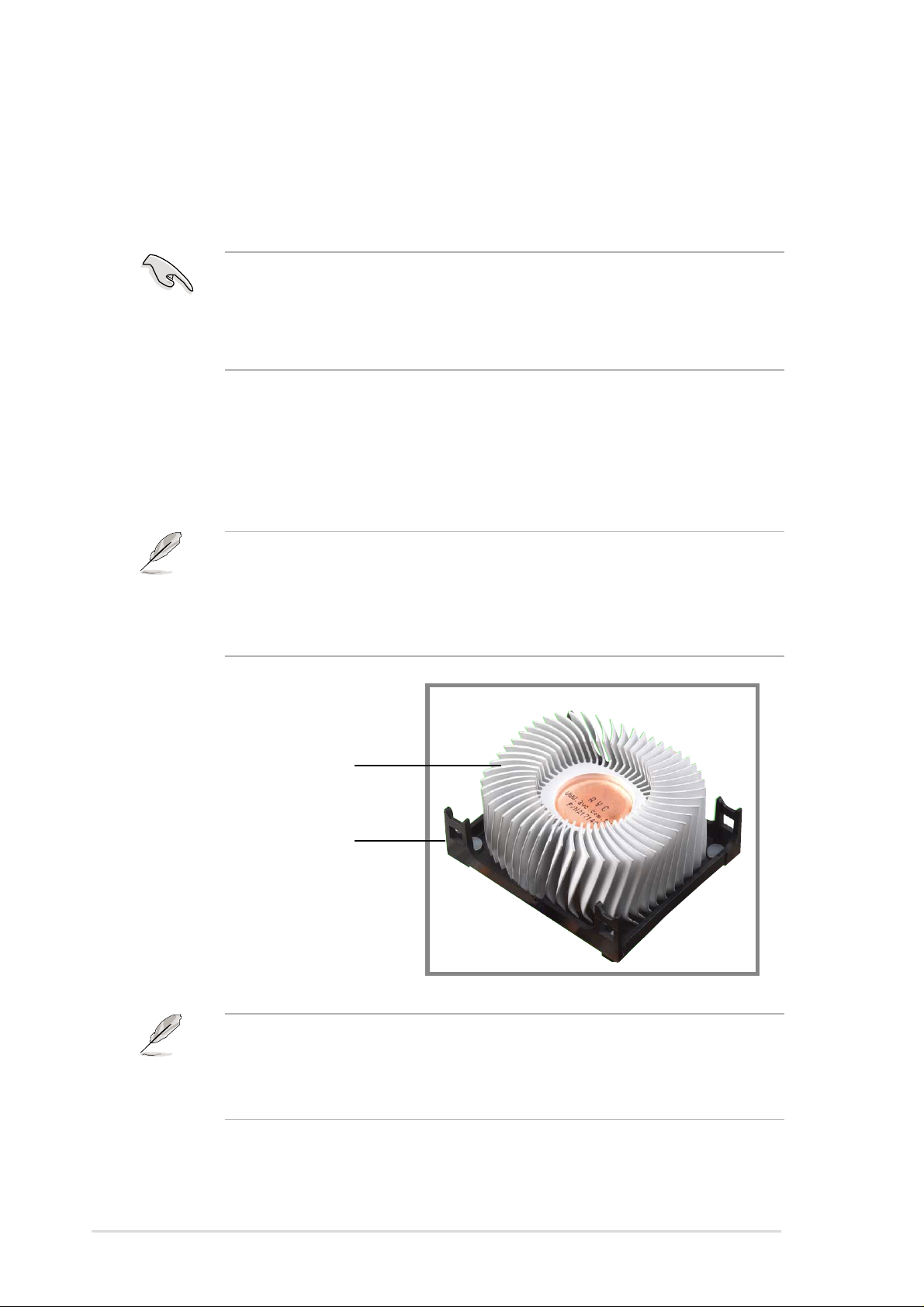
2.4.3 Installing the heatsink and fan
The Intel
®
Pentium
®
4 478/Northwood Processor requires a specially
designed heatsink and fan assembly to ensure optimum thermal condition
and performance.
The retention module base is already installed on the motherboard
upon purchase.
You do not have to remove the retention module base when installing
the CPU or installing other motherboard components.
Follow these steps to install the CPU heatsink and fan.
1. Place the heatsink on top of the installed CPU, making sure that the
heatsink fits properly on the retention module base.
When you buy a boxed Intel Pentium 4 478/Northwood Processor, the
package includes the heatsink, fan, and retention mechanism.
In case you buy a CPU separately, make sure that you use only Intel
certified heatsink and fan.
Your boxed Intel Pentium 4 478/Northwood Processor package should
come with installation instructions for the CPU, heatsink, and the
retention mechanism. If the instructions in this section do not match the
CPU documentation, follow the latter.
Retention Module Base
CPU Heatsink

ASUS P4S133-VM motherboard user guide
15
2. Position the fan with the retention mechanism on top of the heatsink.
Align and snap the four hooks of the retention mechanism to the holes
on each corner of the module base.
Keep the retention locks lifted upward while fitting the retention
mechanism to the module base.
Make sure that the fan and retention mechanism assembly perfectly
fits the heatsink and module base, otherwise you cannot snap the
hooks into the holes.
Retention Hole
Retention Hook Snapped
to the Retention Hole
Retention Lock
16
Chapter 2: Hardware information
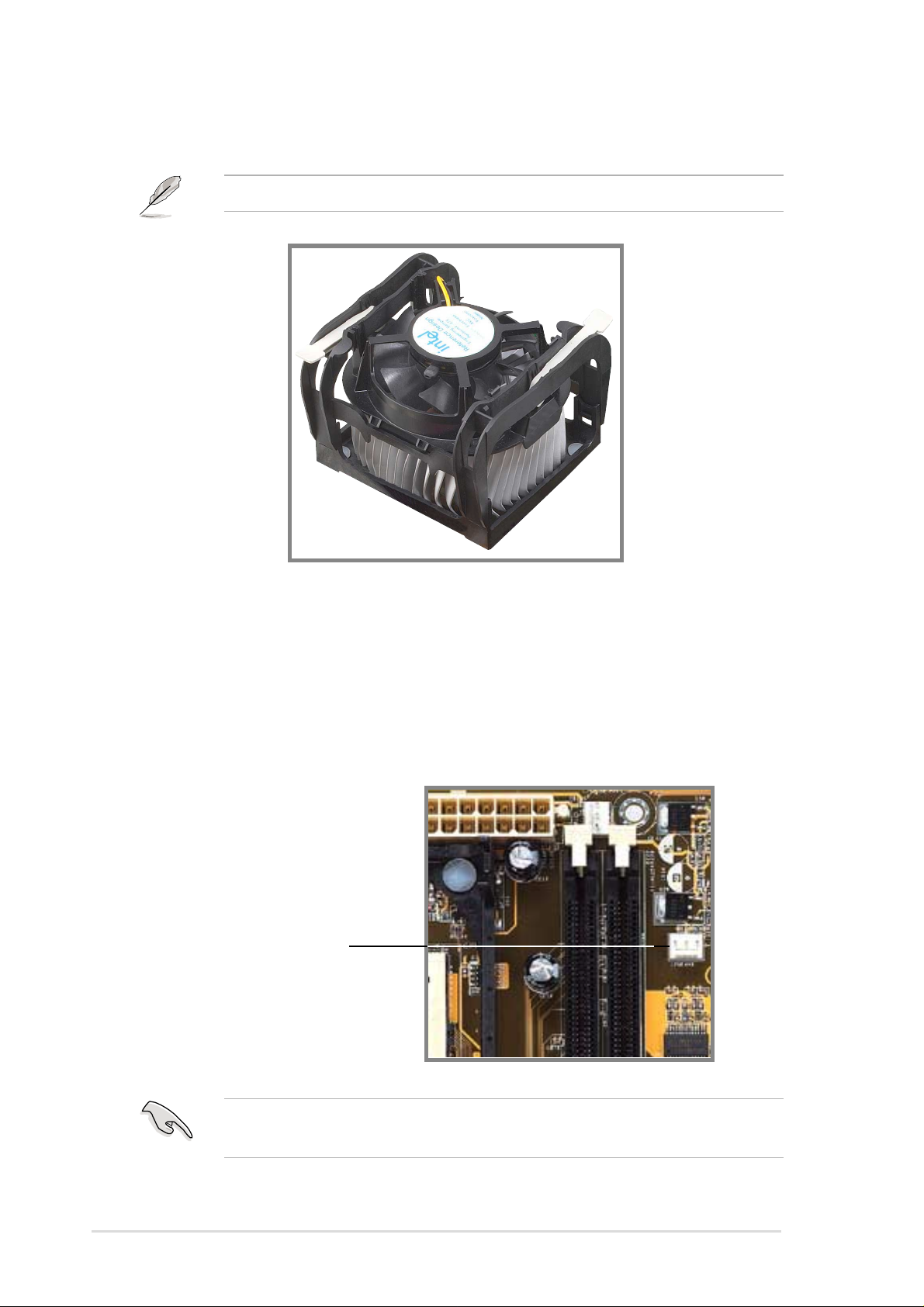
2.4.4 Connecting the CPU fan cable
When the fan, heatsink, and the retention mechanism are in place,
connect the CPU fan cable to the connector on the motherboard labeled
CPUFAN1.
3. Push down the locks on the retention mechanism to secure the
heatsink and fan to the module base.
When secure, the retention locks should point to opposite directions.
Don’t forget to connect the CPU fan connector! Hardware monitoring
errors may occur if you fail to plug this connector.
CPU Fan Connector (CPUFAN1)

ASUS P4S133-VM motherboard user guide
17
2.5 System memory
2.5.1 Overview
This motherboard uses only Dual Inline Memory Modules (DIMMs). Sockets
are available for 3.3Volt (power level) unbuffered Synchronous Dynamic
Random Access Memory (SDRAM) of 16, 32, 64, 128MB, 256, 512 or
1024MB to form a memory size between 16MB and 3GB. One side (with
memory chips) of the DIMM takes up one row on the motherboard.
To use the chipset’s Error Checking and Correction (ECC) feature, you
must use a DIMM with 9 chips per side (standard 8 chips/side + 1 ECC
chip).
Memory speed setup is recommended through Configure SDRAM
Timing by SPD (see 4.4.2 Advanced Chipset Setup).
Install memory in any combination as follows:
IMPORTANT:
• For optimum signal integrity, inserting the DIMMs in the following
order is recommended: DIMM1, DIMM2, DIMM3
• SDRAMs used must be compatible with the current PC133/PC100
SDRAM specification.
• DO NOT mix SDRAMs with VC SDRAMs.
Location 168-pin DIMM Total Memory
DIMM1 (Rows 0&1) SDRAM 16, 32, 64, 128, 256, 512, 1024MB x1
DIMM2 (Rows 2&3) SDRAM 16, 32, 64, 128, 256, 512, 1024MB x1
T otal System Memory (Max 2GB) =
2.5.2 General DIMM Notes
• This motherboard supports SPD (Serial Presence Detect) DIMMs. This
is the memory of choice for best performance vs. stability.
• This motherboard does NOT support registered memory.
• SDRAM chips are generally thinner with higher pin density than EDO
(Extended Data Output) chips.
• BIOS shows SDRAM memory on bootup screen.
• Single-sided DIMMs come in 16, 32, 64,128, 256MB; double-sided
come in 32, 64, 128, 256, 512MB.
18
Chapter 2: Hardware information
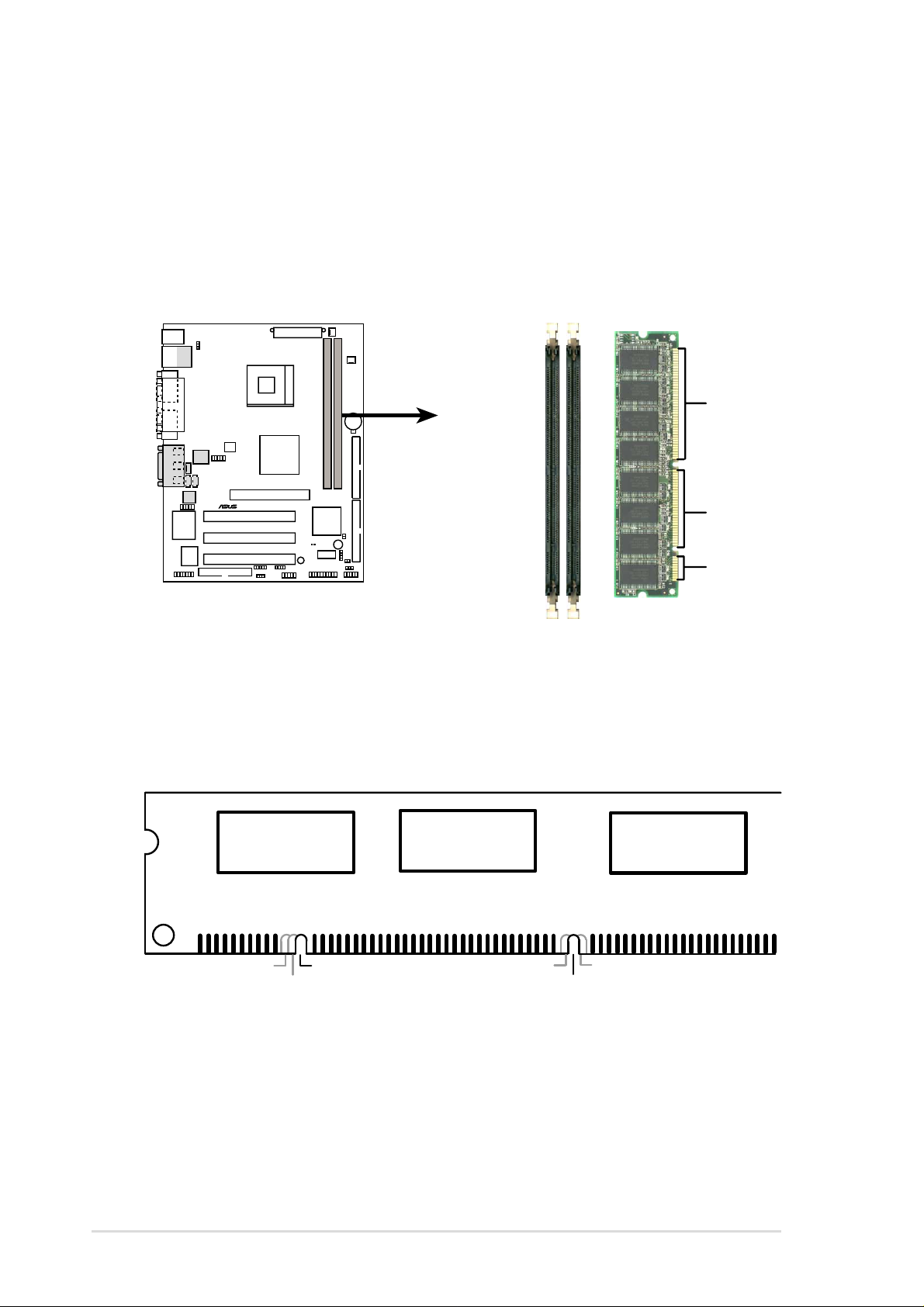
2.5.3 Memory configurations
Insert the module(s) as shown. Because the number of pins are different
on either side of the breaks, the module will only fit in the orientation
shown. DIMM modules are longer and have different pin contact on each
side and therefore have a higher pin density. SIMM modules have the
same pin contact on both sides.
168-Pin DIMM Notch Key Definitions (3.3V)
DRAM Key Position
Voltage Key Position
Unbuffered
RFU
Buffered
Reserved
3.3V
5.0V
The notches on the DIMM module will shift between left, center, or right to
identify the type and also to prevent the wrong type from being inserted
into the DIMM slot on the motherboard. You must ask your retailer the
correct DIMM type before purchasing. This motherboard supports four
clock signals.
P4S133-VM
®
P4S133-VM 168-Pin DIMM Sockets
20 Pins
60 Pins
88 Pins
The DIMMs must be 3.3V Unbuffered for this motherboard. To determine
the DIMM type, check the notches on the DIMMs (see figure below).
 Loading...