


AQUATROL Zone Synchronizing
Boiler Reset Controls
AQ251
USER OPERATION AND MAINTENANCE
APPLICATION
The AQ251 series of AQUATROL® Boiler Reset Controls provides simplified, energy-efficient outdoor temperature compensated control of single-temperature, residential hydronic heating systems. The AQ251 easily converts a single zone heating system into a room-by-room comfort control system, or upgrades a basic, relay-logic zoning system to intelligent “Zone of Greatest Demand” control with outdoor reset for increased energy efficiency and with reduced boiler cycling.
AQ251 boiler controls can ensure ample supply of hot water for both space heating and priority generation of domestic hot water for bathing, dishes and laundry.
When AQ1000 communicating thermostats are used with the AQ251 Zoning Modules, they can use the same wiring as existing thermostats. Night setback operation can be programmed from the AQ251 panel. Thanks to the network communication capability of the AQ251 controls, AQ1000
thermostats in the home can display the actual outdoor temperature when an outdoor sensor is connected to the AQ251 Control Panel.
 WARNING
Only trained, experienced, licensed service technicians should service this Control Panel. The front cover of the AQ251 Control Panel should not be removed, as this will expose the user to potentially dangerous line voltage (120V) electricity.
Congratulations!
The AQUATROL AQ251 installed on your heating system is the most powerful, yet user-friendly hydronic heating control system available on the market for residential and light commercial installations.
This instruction sheet contains all the information you need to program the comfort settings of the AQ251 and to customize its operation for your home or business. For detailed information on the operation of this control, please consult the trained hydronic heating professional that installed the AQ251 control.
|
CONTENTS |
Application ........................................................................ |
1 |
Familiarization with Control .............................................. |
2 |
User Interface .................................................................. |
2 |
LCD Display Panel Layout ................................................ |
3 |
Programming Instructions ................................................. |
4 |
Troubleshooting ................................................................ |
6 |
System Status and Error Codes ....................................... |
6 |
User Menu Structure ......................................................... |
8 |
This AQUATROL AQ251 Control Panel was installed by a trained hydronic heating contractor. To service this product, or for any questions relating to its installation, please contact:
Installing contractor: ________________________________________________________
Address: __________________________________________________________________
Phone: (_______) __________________________________________________________
69-1979-04
AQUATROL ZONE SYNCHRONIZING BOILER RESET CONTROLS
Table 1. AQ251 Models
Model |
Function |
DHW |
Zones |
Zone Control |
AQ25142B |
Reset Boiler Control Panel |
Selectable DHW priority, with |
2 – 16, |
Line voltage circulators or 2-wire zone |
|
with integrated zoning |
optional priority override |
in sets of 4 |
valves |
AQ25144B |
Reset Boiler Control Panel |
Selectable DHW priority, with |
2 – 16, |
24 Vac zone valves with end switches |
|
with integrated zoning |
optional priority override |
in sets of 4 |
|
AQ25110B |
Reset Boiler Control Panel |
Selectable DHW priority, with |
1 |
None; user can add zoning with |
|
with no integrated zoning |
optional priority override |
|
Expansion Zoning Panels (sold |
|
|
|
|
separately) |
AQ251 Approvals and Standards:
Canadian Standards Association: Certified, File No. LR76030
Replacement Parts and Accessories:
AQ1000: non-programmable zone thermostat AQ15100B: Replacement Boiler Reset Control Module AQ15740B: 4-zone valve expansion module AQ15540B: 4-zone pump expansion module AQ10X38: 24 Vac 38 VA transformer
AQ12C10: Replacement sensor, outdoor
AQ12C11: Replacement sensor, supply and return on boiler loop
AQ12C20: Replacement floor / slab sensor
FAMILIARIZATION WITH CONTROL
User Interface
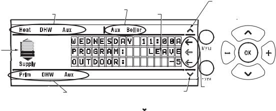
The AQ251 User Interface consists of an LCD screen (16 characters by 3 rows) and a 7 button keypad for navigating the menus as illustrated in Fig. 1.
Keypad
The 7- button keypad provides the following functions.
Menu Press this button to access the User Menu. When pressed while in a sub-menu, the sub-menu’s values are saved before going up one level in the current menu.
Home Press this button to leave the User or Installer Menu and return to the Home Page display screen.
OK Press this button to enter a sub-menu of the active menu item. A menu item is active when the indicator arrow (←) is positioned beside the item.
^ and v Press these buttons to scroll up/down in the menu
items. Pressing one of these buttons automatically exits the edit mode, and the selection moves to the previous or next menu item.
– and + Press these buttons to decrease/increase the value of a selected menu item, or to scroll through a list of pre-defined options.
- If the menu item being modified is a number, the displayed value will decrease/increase by pressing these buttons. When holding the – or + button for more than a second, the values automatically decrease/increase at a faster pace, similar to setting the time on a digital clock radio.
- If the menu item is an option, pressing these buttons scrolls through the list of available options one at a time.
STATUS OF SYSTEM DEMANDS |
STATUS OF SYSTEM OUTPUTS |
DISPLAY AREA SHOWING |
|
- CALL FOR HEAT |
- AUXILIARY OUTPUT ACTIVE |
SYSTEM STATUS AND MENU |
|
- CALL FOR DHW |
- BOILER T-T OUTPUT ACTIVE |
OPTIONS AND SELECTIONS |
|
- SIGNAL ON AUXILIARY INPUT |
|
MADE |
|
GRAPHIC SHOWING |
|
|
|
THE PERCENTAGE |
|
|
|
OF THE BOILER’S |
|
|
|
HEATING CAPACITY |
|
|
|
AT WHICH IT’S |
|
|
|
OPERATING; ARROWS |
|
|
|
ABOVE AND BELOW |
|
|
|
THE BAR SHOW THE |
|
|
|
TREND OF THE |
|
|
|
BOILER’S |
|
|
|
TEMPERATURE |
|
|
|
(UP OR DOWN) |
|
|
|
STATUS OF LINE VOLTAGE OUTPUTS |
DOWN ARROW, IF DISPLAYED, |
||
INDICATES THAT OTHER MENU ITEMS |
|||
- PRIMARY (BOILER) HEAT |
|||
- DHW PUMP |
EXIST BELOW AND CAN BE VIEWED |
||
- AUXILIARY “PUMP” OUTPUT |
BY SCROLLING DOWN WITH |
||
THE |
BUTTON. |
||
|
|||
UP ARROW, IF DISPLAYED, INDICATES THAT OTHER MENU ITEMS EXIST ABOVE AND CAN BE VIEWED BY SCROLLING UP WITH THE BUTTON.
ARROW INDICATES
THE CURRENTLY SELECTED “ACTIVE” MENU ITEM.
M27748
Fig. 1. LCD Dot Matrix Display Layout.
69-1979—04 |
2 |
AQUATROL ZONE SYNCHRONIZING BOILER RESET CONTROLS
LCD Display Panel Layout
The LCD on the AQ251 Control Panel is used to:
—Monitor system status and performance.
—Select and/or modify control settings for the hydronic system.
—Diagnose and troubleshoot system problems.
The layout of the display is logical and simple to navigate. The information displays so that you can see at a glance the system’s operating temperatures, as well as the status of the system equipment, such as a call for heat, DHW pump ON, Boiler T-T terminals energized, etc. Fig. 1 on page 2 illustrates the layout and features of the LCD display panel and keypad.
LCD Display Navigation
This section describes how the keypad is used to navigate the LCD display and menus.
•The LCD displays up to three lines of text at a time. For menus with more than three lines, use the up and down buttons (^ or v) to scroll through the menu options.
•As the menu is scrolled up or down, the indicator arrow (←) shows which menu item is active.
•If the active menu item is part of a list of predefined options (e.g., Day of the Week) press the – or + button to scroll through the available options until the preferred option is displayed. The option is automatically saved when the indicator arrow is scrolled away from the value being edited.
•If the active menu item requires you to define a value (e.g., a setpoint), use the – or + button to decrease or increase the value until the desired value is displayed. The selection will be saved when the indicator arrow is scrolled up or down.
NOTES:
1.When setting times for the setback schedule, you must use the – or + button to change the time.
2.The OK button, when pressed, defaults the time setting to “--:--” (midnight).
•If the active menu item leads to a further sub-menu, pressing the OK button displays the sub-menu options on
the LCD. Scroll through this sub-menu to position the indicator arrow (←) beside the desired menu item to input or modify. Choose one of the options provided or input the desired value for the menu item. When satisfied, scroll to another item and your selection will be saved.
•To define or modify another item within the same menu,
scroll the up and down buttons (^ or v) until the indicator arrow (←) is beside the desired option. Use the – or + buttons to set the value for that item.
•To move back (up) one level within a menu, press the Menu button.
•To return to the Home Page display, press the Home button.
NOTE: The AQ251 automatically returns to the Home Page display after 60 minutes of inactivity on the keypad.
HOME PAGE DISPLAY
The Home Page is the default view displayed on the AQ251 Control Panel's LCD screen.
There are two Home Page views - Simple and Detail.
•Simple view shows 3 lines of text and is a brief description of the system operation.
•Detail view includes the same 3 lines plus 10 lines of additional information. Detail view is the factory default.
The choice of the Simple or Detail Home Page view is made from the USER MENU > PREFERENCES/TIME menu option.
The Home Page display information for the Simple and Detail views is illustrated in Fig. 2.
|
LCD DISPLAY |
|
|
HOME PAGE (SIMPLE) |
|
|
|
WEDNESDAY |
9:30A |
|
|
|
PROGRAM: |
LEAVE |
|
|
OUTDOOR: |
-5 |
|
HOME PAGE (DETAIL) |
WEDNESDAY |
9:30A |
|
|
RETRN SLEEP WAKE OCC UNOCC |
||
|
PROGRAM: |
LEAVE |
|
|
OUTDOOR: |
-5 |
WWSD - - |
|
TARGET: |
180 |
|
|
BOILER: |
180 |
|
|
RETURN: |
160 |
|
|
DHW: |
100 |
|
|
ZONE COUNT: |
31 |
|
Fig. 2. Home Page displays (Simple and Detail).
KEYPAD
Menu
Home
M27749
3 |
69-1979—04 |
 Loading...