


OPERATION MANUAL
© ZOOM Corporation
Reproduction of this manual, in whole or in part, by any means, is prohibited.
precautions safety and Usage
Usage and safety precautions
SAFETY PRECAUTIONS
In this manual, symbols are used to highlight warnings and cautions that you must read to prevent accidents. The meanings of these symbols are as follows:
This symbol indicates explanations about extremely dangerous matters. If users ignore this warning and handle the device incorrectly, serious injury or death could result.
This symbol indicates explanations about dangerous matters. If users ignore this caution and handle the device incorrectly, bodily injury and damage to the
equipment could result.
Please observe the following precautions to ensure safe use of this unit.
Power requirements
Since the power consumption of this unit is high, we recommend using the AC adapter. When using batteries, use either alkaline or nickel-metal hydride batteries.
Operation using an AC adapter
•Be sure to use only a DC5V/1A/center plus AC adapter (ZOOM AD-14). Use of an AC adapter other than that specified could damage the unit, cause malfunction or result in a fire or other trouble.
•Connect the AC adapter only to an outlet that supplies the rated AC voltage required by the adapter.
Before using the R24 in other countries (or regions) where the power voltage differs from AC 100 V, always consult with a store that handles ZOOM products and use a suitable AC adapter.
•When disconnecting the AC adapter from an outlet, always pull the body of the adapter itself.
•During lightning storms or when not using the unit for an extended period of time, disconnect the AC
adapter from the AC outlet.
Operation using batteries
•Use six conventional 1.5-volt AA batteries
•The R24 cannot recharge batteries.
•Read battery labels carefully.
•When not using the unit for an extended period of time, remove the batteries from the unit.
•If a battery leak should occur, wipe the battery compartment and the battery terminals carefully to remove all battery residue.
•Always close the battery compartment cover when using the unit.
About grounding
Depending on the placement conditions of the unit, a slight electrical charge might be felt when touching a metal part of the R24. If you wish to avoid this, ground the unit by connecting an external ground to a screw on the rear panel. To avoid danger from electricity, never connect it to any of the following for grounding.
•Water pipes (risk of electric shock)
•Gas pipes (risk of explosion)
•Telephone wiring grounds or lightning arrestors (danger during lightning strikes)
Operating environment
Avoid using the R24 where it might be exposed to the following conditions that could cause it to malfunction.
• Extremely high or low temperatures • Very high humidity or splashing water • Excessive dust or sand
• Excessive vibrations
Handling
Never put vases or other items filled with liquids on the
R24 as they could cause electric shock.
The R24 is a precision instrument. Do not put unnecessary pressure on the keys and other controls. Use of
excessive force and dropping or bumping the unit, for example, could cause the unit to break.
Connecting cables with input and output jacks
Always turn the power OFF for all equipment before connecting any cables. In addition, make sure to disconnect all connection cables and the AC adapter
before moving the unit.
Alterations
Never open the case or attempt to modify the product in any way since this could result in damage to the unit.
Zoom Corporation will not take any responsibility for damage resulting from alterations to the unit.
Volume
Do not use the R24 at a loud volume for a long time. Doing so could damage hearing.
Usage Precautions
Interference with other electrical equipment
In consideration of safety, the R24 has been designed to provide maximum protection against the emission of electromagnetic radiation from the device and to be protected from external interference. However, equipment that is very susceptible to interference or that emits powerful electromagnetic waves could result in interference if placed near the R24. If this occurs, place the R24 and the other device farther apart.
With any type of electronic device that uses digital control, including the R24, electromagnetic interference could cause malfunction, corrupt or destroy data and result in other unexpected trouble. Always use caution around other devices.
Cleaning
Use a soft cloth to clean the panels of the unit if they become dirty. If necessary, use a damp cloth that has been wrung out well. Never use an abrasive cleanser, wax or solvent including alcohol, benzene and paint thinner.
Malfunction
If the unit becomes broken or malfunctions, immediately disconnect the AC adapter, turn the power OFF and disconnect other cables. Contact the store where you bought the unit or Zoom service with the following information: product model, serial number and specific symptoms of failure or malfunction, along with your name, address and telephone number.
Copyrights
Except for personal use, unauthorized recording of copyrighted sources, including CDs, records, tapes, video products, broadcasts, is prohibited. Zoom Corporation does not bear any responsibility for any consequences related to copyright law infringement.

 The SD symbol and
  SDHC symbol are trademarks.
  Windows®/Windows Vista® are trademarks or
registered trademarks of Microsoft®.  Macintosh® and Mac OS® are trademarks or registered trademarks of Apple Inc.
  Steinberg and Cubase are trademarks or registered trademarks of Steinberg Media Technologies GmbH Inc.
  Intel® and Pentium® are trademarks or registered trademarks of Intel® Corporation. AMD Athlon™ is a trademark or registered trademark of Advanced Micro Devices, Inc.
 All other trademarks, product names, and company names mentioned in this documentation are the property of their respective owners.
All trademarks and registered trademarks mentioned in this manual are for identification purposes only and are not intended to infringe on the copyrights of their respective owners.
1

Introduction |
After reading it, please keep the manual along with the warranty in a safe place. |
|
Please read through this manual carefully in order to understand the R24 functions well. |
Thank you very much for purchasing the ZOOM R24 Recorder:Interface:Controller:Sampler. We will call it simply the “R24” in this manual. The R24 has the following features.
■ Multitrack recorder that can use up to 32 GB SDHC cards
The R24 can record up to 8 tracks simultaneously, allowing serious live recording. For example, you can record a complete band on individual tracks or a drum kit with multiple microphones. After making linear PCM recordings (WAV format) at 16/24-bit and 44.1/48-kHz sampling rate, you can transfer recorded files to your computer to use them in DAW software. You can even connect two R24s together with a USB cable, allowing recording of up to 16 tracks.
■ Hi-Speed USB (USB 2.0) audio interface
You can use the R24 and its many input and output jacks as a Hi-speed USB (USB 2.0) audio interface. As an interface, the R24 can handle 8 inputs and 2 outputs at a maximum of 24-bit and 96 kHz. Its effects can even be used (at 44.1 kHz only). The unit can also operate using USB bus power.
■ Usable as a control surface for DAW software
The R24 has functions that enable control of DAW software on a computer via a USB cable.
You can operate its transport, including play, record and stop keys and physically control onscreen faders. You can also assign various
DAW functions to the R24’s F1–F5 function keys. (The assignable functions depend on the DAW software.)
■ Diverse effects
The R24 has two types of built-in effects. Insert effects can be applied to specific channel signals and send-return effects can be used through the mixer send-return bus. You can use these effects in a wide variety of ways, including during recording, by applying them to already recorded tracks, and in the mastering process of mixing down and bouncing.
■ Comprehensive built-in mixer features
The R24 is equipped with a digital mixer that allows you to mix the playback of audio tracks.
You can adjust the volume, pan, EQ and effects for each track and mix them into a stereo signal.
■ Handles a variety of input sources including guitars, microphones and line-level equipment
The R24 is equipped with 8 input jacks that accept both XLR and standard phone connectors, including 1 that can handle high impedance and 6 that can supply phantom power (24 V or 48 V). The R24 can handle all types of sources, including high impedance guitars and basses, dynamic and condenser microphones, and synthesizers and other line level instruments. It also has two built-in high-performance microphones that are convenient for recording acoustic guitars and vocals.
■ Exchange files with computers and USB memory devices
The R24 has a USB 2.0 jack that allows high speed data transfer. You can transfer WAV audio files recorded on the R24 to a computer just by dragging and dropping. You can also exchange files with a connected USB memory device without using a computer.
■ 24-voice built-in sampler can be triggered using 8 pads and 3 bank keys
Use the sampler to assign sounds to each track (pad) and create loops. Play the pads in realtime, and even create performance data for a complete song by combining loops. By simply lining up drum loops from the included USB memory, anyone can easily create professionalquality backing parts and basic tracks. While listening to loop playback, you can record audio on other tracks because the R24 recorder and sampler work together seamlessly.
■ Rhythm and metronome functions can be used as guides and backing tracks
The unit starts with over 400 rhythm patterns that use the built-in drum machine, and you can create your own original patterns using both real-time and step input. You can output the metronome sound only to the headphones, allowing you to send just a click to the drummer in a live situation, while the signals from the output jacks are sent to a mixer.
Note: For the improvement of this product, its specifications are subject to change without notice.
Introduction
2

Contents
Contents
Usage and safety precautions . . |
. . |
. |
1 |
Introduction . . . . . . . . |
. . |
. |
2 |
Contents . . . . . . . . . . |
. . |
|
.3 |
R24 operation flow |
|
|
5 |
Basic recording guide . . . . . |
. . |
. |
7 |
Panel layout and functions |
|
|
9 |
Connections . . . . . . . . |
. . |
. |
11 |
SD card installation . . . . . . |
. . |
|
12 |
Powering the unit |
|
|
13 |
Turning the power on & off . . . . |
. . |
|
14 |
Date & time setting . . . . . . |
. . |
. 14 |
|
Switch and key operation overview |
|
|
15 |
Display information |
|
|
16 |
UNDO/REDO |
|
|
|
Recording preparations
R24 recording flow . . . . . . . . |
. 17 |
Creating a new project . . . . . . . |
17 |
Connecting instruments . . . . . . |
. 18 |
Making mono settings . . . . . . . |
18 |
Hi-Z
Phantom power
Stereo settings & status keys |
19 |
Built-in mics
Stereo line inputs
Stereo link . . . . . . . . . . . 20 Setting the tempo 21 Preparing a rhythm track . . . . . . . 22
Track recording
Recording the first track . . . . . . . 23
Adjusting gain, recording and playback
Changing the playback take . . . . . 25
Swapping tracks
Overdubbing
Recording additional tracks |
27 |
Playing already recorded tracks
Recording and playback
Re-recording
Automatic punch-in/punch-out . . . . . 29 Manual punch-in/punch-out . . . . . 30
Playback
Project playback . . . . . . . . . 31 Repeat playback of a specific section
(A-B repeat) . . . . . . . . . . . 32 Using the counter and marks to locate . . 33
Mark functions
Tools
Tuner |
35 |
Metronome . . . . . . . . . . . |
36 |
16-track synchronized recording |
|
with two units . . . . . . . . . . |
37 |
Mixing
R24 mixing process . . . . . . . . |
39 |
EQ, pan and send level track settings . . |
40 |
Track parameters . . . . . . . . |
. 41 |
Mix down/Bounce
Combine multiple tracks into 1–2 tracks . |
43 |
Bouncing |
|
Using a mastering effect . . . . . . |
. 45 |
Recording to the master track . . . . |
. 46 |
Sampler functions
Using the sampler to make songs . . . |
47 |
Overview of sampler functions . . . . |
. 48 |
Assigning tracks . . . . . . . . . |
49 |
Loop settings |
50 |
Playing the pads . . . . . . . . . |
52 |
Playback methods |
|
Global quantization |
|
Creating a sequence . . . . . . . . |
53 |
Real-time input |
|
Step input
3

For details about use with a computer, refer to the Audio Interface Manual (PDF) on the CD-ROM included with the unit.
Editing a sequence . . . . . . . . |
56 |
Inserting and deleting beats |
|
Changing the time signature |
|
Playing back a sequence |
59 |
Changing the BPM . . . . . . . . |
. 60 |
Changing tempo without changing pitch . |
61 |
Trimming unnecessary parts of audio files |
. 63 |
Setting fade-ins and fade-outs . . . . |
. 64 |
Rhythm function
Overview of rhythm functions |
65 |
Playing rhythm patterns . . |
. . . . . 66 |
Projects
Project overview . . . . . . . |
. . |
89 |
Project protection |
|
89 |
Creating a new project . . . . . |
. . |
90 |
Selecting projects and files . . . . |
. . |
91 |
Project and file information . . . . |
. . |
92 |
Copying projects and files . . . . |
. . |
93 |
Changing project and file names |
|
94 |
Deleting projects and files . . . . |
. . |
95 |
Dividing files . . . . . . . . |
. . |
. 96 |
Sequential playback of projects |
|
97 |
Recording settings . . . . . . |
. . |
. 99 |
Selecting a rhythm pattern |
|
|
|
|
|
|
Selecting the drum kit |
|
System/SD cards |
|
|
||
Playing pad sounds |
67 |
|
Adjusting the display . . . . . . . |
|
. 100 |
|
Switching banks |
|
|
Backlight and contrast |
|
|
|
Drum rolls |
|
Changing the SD card while the |
|
|
||
Pad sensitivity |
|
|
power is on . . . . . . . . . . |
|
101 |
|
Creating a rhythm pattern . . . . . . |
68 |
Formatting SD cards . . . . . . . |
|
. 102 |
||
Setting bars, time signature, quantization |
|
Checking card capacities |
|
102 |
||
Checking remaining memory |
|
Checking the system version |
|
103 |
||
Real-time and step input |
|
Setting the battery type . . . . . . |
|
103 |
||
Copying rhythm patterns . . . . . . |
. 71 |
Phantom power settings . . . . . . |
|
104 |
||
Deleting rhythm patterns |
72 |
|
|
|
|
|
Changing rhythm pattern names . . . . |
73 |
USB |
|
|
||
Import rhythm patterns . . . . . . . |
74 |
|
|
|
|
|
Connecting with a computer . . . . |
. |
105 |
||||
Setting volume and stereo placement . . |
75 |
|||||
Card reader . . . . . . . . . . |
|
106 |
||||
Assigning rhythm patterns to tracks . . |
. 76 |
|
||||
Using USB memory to save and |
|
|
||||
|
|
|
|
|||
Effects |
|
|
import data |
|
107 |
|
|
|
Audio interface/control surface |
|
110 |
||
Effect and patch overview . . . . . . |
77 |
|
|
|
|
|
Input and output of insert and |
|
|
|
|
|
|
send-return effects |
79 |
Rhythm pattern list . . . . . . . . |
|
113 |
||
Effect patch selection |
|
Effect types and parameters |
|
115 |
||
Setting the insert effect position . . . . |
81 |
Effect patch list |
|
126 |
||
Patch editing |
83 |
Error message list . . . . . . . . |
|
132 |
||
Patch saving . . . . . . . . . . |
. 85 |
Specifications |
|
133 |
||
Patch importing |
86 |
Troubleshooting . . . . . . . . |
. |
134 |
||
Using the insert effect only for monitoring |
. 87 |
Upgrading the firmware |
|
135 |
||
|
|
Index . . . . . . . . . . . . |
. |
137 |
||
Contents
4
flow operation R24
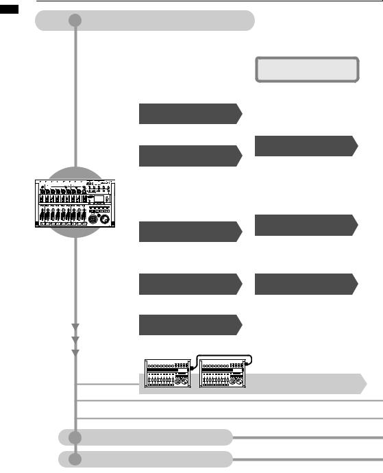
R24 operation flow
Multitrack recorder |
|
24 audio tracks |
|
||
|
|
|
|||
|
|
|
|
|
|
|
Recording preparations |
|
|
Recording |
|
|
|
||||
|
|
|
|
|
|
Make various settings for the built- |
|
|
|
||
in microphones, connected musical |
|
Effects |
P77 |
||
instruments and other input sources, |
|
|
|
||
signals and tracks. Use the tuner and |
|
|
|
||
the metronome to prepare for a new |
|
|
|
||
project or a live performance. |
|
|
|
||
Project creation |
P17 |
Prepare a project to save recordings.
• NEW PROJECT
Instrument connection settings P18,19
This recorder can handle various instruments.
• Built-in mics |
P19 |
• Hi-Z |
P18 |
• PHANTOM power |
P18 |
• Stereo link |
P20 |
Performance tools |
|
• TUNER |
P35 |
• METRONOME |
P36 |
Insert effects |
P79 |
|
|
1. After input jacks |
|
Track recording |
P23 |
Record the input signals from connected input sources to tracks. Undo the previous recording if the results were unsatisfactory.
• UNDO/REDO |
P16 |
Playback P31
Play up to 24 tracks of mono and stereo audio.
• A-B REPEAT |
P32 |
• MARK settings |
P33 |
USB connection
Track assignment |
P49 |
Loop settings |
P50 |
Assign audio files and rhythm patterns |
Set assigned audio files and rhythm |
||
to tracks. |
|
patterns to loop. |
|
Create rhythm |
|
|
|
patterns |
P68 |
|
|
Create rhythm patterns or use the unit's preset patterns.
Linking two units |
|
SYNCREC |
P37 |
Audio interface
Control surface
5
8 simultaneous tracks of stereo and mono recording
Apply various effects to process input signals, recorder playback and sound generator output.
• PATCH EDIT, etc. |
P83~ |
Track mixer
330 types of effects
Mixing mixdown
Mixer P39
Adjust recorded tracks using the track mixer.
Effects used on specific track signal paths
2. Desired tracks in mixer
Overdubbing P27
Record new tracks while playing back previously recorded tracks.
Re-recording
Re-record just part of a recorded file.
• PUNCH IN/OUT |
P29 |
3. Before the MASTER fader
Send-return effect
There are two internal send/return effects in the built-in mixer—a chorus/ delay effect and a reverb effect. Adjust the effect send levels for each mixer track individually.
Mixing P39
Adjust parameters for each track.
• EQ • Volume • Pan |
P40 |
Create a sequence P53
Use looped material to create performance data for an entire song.
Mixdown
Combine multiple tracks into one stereo track.
• Bounce |
P43 |
• Recording a MASTER track |
P46 |
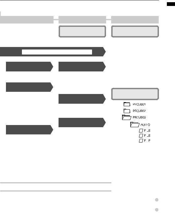
Editing & output
Project P89
Recorded sound files and settings can be managed and stored on a per song basis as a project and then edited in various ways.
• PROJECT/FILE |
|
|
|
P91 |
||||||
• INFORMATION |
|
|
|
P92 |
||||||
• DIVIDE |
|
|
|
P96 |
||||||
• COPY |
|
|
|
P93 |
||||||
• DELETE |
|
|
|
P95 |
||||||
• RENAME |
|
|
|
P94 |
||||||
• PROTECT |
|
|
|
P89 |
||||||
SD card |
P101 |
|||||||||
|
|
|
|
|
|
|
|
|
|
|
|
|
|
|
|
|
|
|
|
|
|
|
|
|
|
|
|
|
|
|
|
|
|
|
|
|
|
|
|
|
|
|
|
|
|
|
|
|
|
|
|
|
|
|
|
|
|
|
|
|
|
|
|
|
|
|
|
|
|
|
|
|
|
|
|
|
|
|
|
|
|
|
|
|
|
|
|
|
|
|
|
|
|
|
|
|
|
|
|
|
|
|
|
|
|
|
|
|
|
Card reader |
P106 |
|
|
|
|
USB memory |
P107 |
|
|
Send signals between DAW software and audio equipment.
P110~ |
■ Audio interface manual |
Operate DAW software with the R24. |
|
|
|
P110~ |
■ Audio interface manual |
flow operation R24
6
Basic recording guide Make a quick recording with the R24
Here we explain how to record in stereo with the built-in microphones on the unit's left and and how to record an electric guitar the high impedance input.
an SD card and turn power on.
STEP 2 |
a new project. |
1 |
|
Press |
Change menu |
|
|||
2 Select NEW. |
Use the up/ |
||
|
|
|
|
|
|
|
down keys |
 Press
Press
3 Confirm the project name, etc.
Change menu
4 Select EXECUTE.
Use the up/ down keys
 Press
Press
Return to the main screen.
Ref: Projects |
P89 |
STEP 3 the input source ON.
Using built-in mics (stereo recording)
1 |
|
|
Turn the INPUT 7 & 8 MIC |
|||
|
|
switch ON. |
||||
2 |
|
|
|
|
|
|
|
|
|
|
|
|
|
Press the status keys of INPUTS 7 & 8 |
||||||
until their indicators light red. |
||||||
|
|
|
|
|
Press repeatedly |
|
|
|
|
||||
|
|
|
|
|
|
|
|
|
|
|
When red, recording is possible |
||
|
|
|
|
|||
|
|
|
|
|
|
|
or
Recording an electric guitar
(high-impedance mono input)
1 |
Connect the guitar to INPUT 1. |
||||
2 |
|
Turn the INPUT 1 Hi-Z |
|||
|
switch ON. |
||||
3 |
Press the status key of INPUT 1 until the |
||||
indicator lights red. |
|||||
|
|
|
|
Press repeatedly |
|
|
|
||||
|
|
|
|
|
|
|
|
|
When red, recording is possible |
||
|
|
|
|||
|
|
|
|
|
|
NOTE
•Hi-Z is only on INPUT 1, and the built-in stereo microphones function only on tracks 7 & 8.
•Tracks 7 & 8 correspond to INPUT 7 & 8 and are set up as two mono tracks by default. To use the built-in mics for a stereo recording, set stereo link to create one stereo track.
Ref: Stereo link |
P20 |
Connecting instruments |
P18, 19 |
|
7
STEP 4 |
the input sensitivity, |
monitoring level and output |
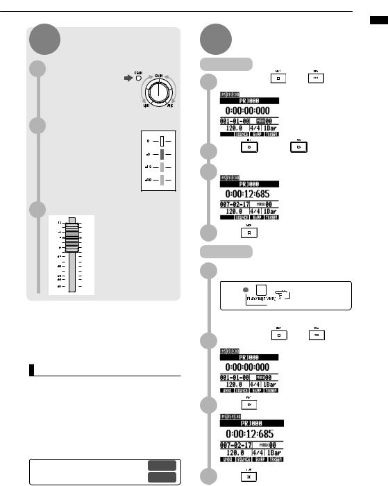
the input sensitivity (GAIN)
the GAIN of each INPUT so that their PEAK indicators blink occasionally.
2 Adjust the recording level
The red (0 dB) indicator of the level meter should not light when you apply an insert effect to an INPUT. Adjust the patch level, for example, if necessary.
3 |
the monitoring level |
Adjust the monitoring |
|
|
level of an instrument |
|
with the fader of the |
|
track it is being recorded |
|
on. (INPUT 1 would be |
|
track 1, 9 or 17, for |
|
example.) |
NOTE
•If an input signal distorts during recording, refer to STEP 4 and adjust the input sensitivity and recording level.
•After recording has completed, the “Please wait” pop-up will be displayed. Do not turn the power OFF or take the SD card out while this pop-up is open. Doing so could damage data or cause other problems.
|
Ref: Recording methods in detail |
P17~ |
|
Using insert effects |
P81 |
|
|
STEP 5 —Complete—Play
Recording |
|
|
While pressing |
press |
to |
1 move to the beginning. |
|
|
2 recording.Press |
and then |
to start |
|
3 |
Start performing. |
|
|
|
|
Counter starts |
|
4 |
Press |
to stop recording. |
|
Playback
1 Press the status key to end recording standby and make the light green.
Press repeatedly
When green, playback is possible
The track changes from recording standby
(red) to playback standby (green).
While pressing |
press |
to |
2 move to the beginning. |
|
|
3 Press |
to start playback. |
4 Press |
to stop playback. |
guide recording Basic
8

functions and layout Panel
Panel layout and functions
 Rear panel
Level meters |
|
|
|
|
|
|
|
|
|
Input section |
|
|
|
|
|
|
|||||||||||||||||||||||||
(1/9/17~8/16/24, MASTER) |
|
|
|
|
|
|
|
|
|
|
|
|
|
|
|
|
|
|
|
|
|
|
|
|
|
|
|
|
|
|
|||||||||||
|
|
|
|
|
|
|
|
|
|
|
|
|
|
|
|
|
|
|
|
|
|
|
|
|
|
|
|
|
|
|
|
|
|
|
|
|
|
|
|
|
|
|
|
|
|
|
|
|
|
|
|
|
|
|
|
|
|
|
|
|
|
|
|
|
|
|
|
|
|
|
|
|
|
|
|
|
|
|
|
|
|
|
|
|
|
|
|
|
|
|
|
|
|
|
|
|
|
|
|
|
|
|
|
|
|
|
|
|
|
|
|
|
|
|
|
|
|
|
|
|
|
|
|
|
|
|
|
|
|
|
|
|
|
|
|
|
|
|
|
|
|
|
|
|
|
|
|
|
|
|
|
|
|
|
|
|
|
|
|
|
|
|
|
|
|
|
|
|
|
|
|
|
|
|
|
|
|
|
|
|
|
|
|
|
|
|
|
|
|
|
|
|
|
|
|
|
|
|
|
|
|
|
|
|
|
|
|
|
|
|
|
|
|
|
|
|
|
|
|
|
|
|
|
|
|
|
|
|
|
|
|
|
|
|
|
|
|
|
|
|
|
|
|
|
|
|
|
|
|
|
|
|
|
|
|
|
|
|
|
|
|
|
|
|
|
|
|
|
|
|
|
|
|
|
|
|
|
|
|
|
|
|
|
|
|
|
|
|
|
|
|
|
|
|
|
|
|
|
|
|
|
|
|
|
|
|
|
|
|
|
|
|
|
|
|
|
|
|
|
|
|
|
|
|
|
|
|
|
|
|
|
|
|
|
|
|
|
|
|
|
|
|
|
|
|
|
|
|
|
|
|
|
|
|
|
|
|
|
|
|
|
|
|
|
|
|
|
|
|
|
|
|
|
|
|
|
|
|
|
|
|
|
|
|
|
|
|
|
|
|
|
|
|
|
|
|
|
|
|
|
|
|
|
|
|
|
|
|
|
|
|
|
|
|
|
|
|
|
|
|
|
|
|
|
|
|
|
|
|
|
|
|
|
|
|
|
|
|
|
|
|
|
|
|
|
|
|
|
|
|
|
|
|
|
|
|
|
|
|
|
|
|
|
|
|
|
|
|
|
|
|
|
|
|
|
|
|
|
|
|
|
|
|
|
|
|
|
|
|
|
|
|
|
|
|
|
|
|
|
|
|
|
|
|
|
|
|
|
|
|
|
|
|
|
|
|
|
|
|
|
|
|
|
|
|
|
|
|
|
|
|
|
|
|
|
|
|
|
|
|
|
|
|
|
|
|
|
|
|
|
|
|
|
|
|
|
|
|
|
|
|
|
|
|
|
|
|
|
|
|
|
|
|
|
|
|
|
|
|
|
|
|
|
|
|
|
|
|
|
|
|
|
|
|
|
|
|
|
|
|
|
|
|
|
|
|
|
|
|
|
|
|
|
|
|
|
|
|
|
|
|
|
|
|
|
|
|
|
|
|
|
|
|
|
|
|
|
|
|
|
|
|
|
|
|
|
|
|
|
|
|
|
|
|
|
|
|
|
|
|
|
|
|
|
|
|
|
|
|
|
|
|
|
|
|
|
|
|
|
|
|
|
|
|
|
|
|
|
|
|
|
|
|
|
|
|
|
|
|
|
|
|
|
|
|
|
|
|
|
|
|
|
|
|
|
|
|
|
|
|
|
|
|
|
|
|
|
|
|
|
|
|
|
|
|
|
|
|
|
|
|
|
|
|
|
|
|
|
|
|
|
|
|
|
|
|
|
|
|
|
|
|
|
|
|
|
|
|
|
|
|
|
|
|
|
|
|
|
|
|
|
|
|
|
|
|
|
|
|
|
|
|
|
|
|
|
|
|
|
|
|
|
|
|
|
|
|
|
|
|
|
|
|
|
|
|
|
|
|
|
|
|
|
|
|
|
|
|
|
|
|
|
|
|
|
|
|
|
|
|
|
|
|
|
|
|
|
|
|
|
|
|
|
|
|
|
|
|
|
|
|
|
|
|
|
|
|
|
|
|
|
|
|
|
|
|
|
|
|
|
|
|
|
|
|
|
|
|
|
|
|
|
|
|
|
|
|
|
|
|
|
|
|
|
|
|
|
|
|
|
|
|
|
|
|
|
|
|
|
|
|
|
|
|
|
|
|
|
|
|
|
|
|
|
|
|
|
|
|
|
|
|
|
|
|
|
|
|
|
|
|
|
|
|
|
|
|
|
|
|
|
|
|
|
|
Control section
Built-in mic |
Fader section |
Transport section |
|
|
|||
|
|
|
Display section |
|
|
|
Display |
|
|
TEMPO indicator |
|
Right side panel |
|
|
|
|
|
TEMPO key |
Soft keys |
|
|
Bottom panel (not shown) |
|
|
|
Battery compartment |
|
SD card slot |
USB HOST port |
USB DEVICE port |
|
9
Input section
PHANTOM |
MIC |
METRONOME |
switch |
switch |
switch |
Hi-Z switch
PEAK indicator GAIN controls (1~8) BALANCE control
Fader section |
Control section |
|
PROJECT key |
|
EFFECT key |
||
Status keys |
|
TOOL key |
|
|
USB key |
||
|
|
||
(1/9/17~8/16/24, MASTER) |
|
|
|
Track indicator |
RHYTHM key |
|
|
Master indicator |
|
|
|
|
|
|
|
|
1-8Tr key |
|
|
|
|
9-16Tr key |
TRACK key |
|
|
17-24Tr key |
PAN/EQ key |
|
Transport section |
|
|
|
|
|
|
|
AUTO PUNCH IN/OUT key |
marker key |
marker key |
|
A-B REPEAT key |
MARK/CLEAR key |
|
Faders
(1/9/17~8/16/24,
MASTER)
REW key |
FF key |
STOP key |
PLAY key |
REC key |
Pad
ENTER key
REPEAT/STOP key
Cursor keys
Rear panel |
|
EXIT key |
|
|
|
|
|
DIAL |
POWER switch |
OUTPUT jacks |
PHONES jack |
|
|
|
|
|
|
|
|
|
|
|
|
|
|
|
|
|
|
|
|
|
|
|
|
|
|
|
|
|
|
|
|
|
|
|
|
|
|
|
|
|
|
|
|
|
|
|
|
|
|
|
|
|
|
|
|
|
|
|
|
|
|
|
|
|
|
|
|
|
|
|
|
|
|
|
|
|
|
|
|
|
|
|
|
|
|
|
|
|
|
|
|
|
|
|
|
|
|
|
|
|
|
|
|
|
|
|
|
|
|
|
|
|
|
|
|
|
|
|
|
|
|
|
|
|
|
|
|
|
|
|
|
|
|
|
|
|
|
|
|
|
|
|
|
|
|
|
|
|
|
|
|
|
|
|
|
|
|
|
|
|
|
|
|
|
|
|
|
|
|
|
|
|
|
|
|
|
|
|
|
|
|
|
|
|
|
|
|
|
|
|
|
|
|
|
|
|
|
DC5V1A |
jack |
OUTPUT |
control |
|
|
|
|
|
PHONES |
control |
INPUT jacks |
|
|
|||||||||||||||||||
functions and layout Panel
10
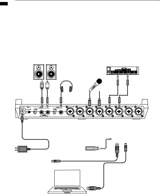
Connections
Connections
Refer to the following to connect other devices, including instruments, microphones, audio equipment and computers.
Outputs
Set the METRONOME switch to output it to only the PHONES jack or also to the
OUTPUT jacks.
Stereo system, speakers with built-in amplifiers, etc.
Turn off the system’s power (or turn down the volume) before connecting speakers to avoid damage.
Rear panel
AC adapter
Always use a ZOOM AD-14 adapter, which is designed for use with this unit.
Inputs
Connect cables with XLR or mono phone plugs (balanced or unbalanced) to the
INPUT jacks.
Microphones
In order to supply phantom power to a condenser microphone, first connect the microphone to INPUT 5 or 6 and then turn the PHANTOM switch ON. Phantom power can also be provided to INPUTS 3,4,7 and 8 (see P104).
Devices with stereo outputs
When using a synthesizer or a CD player, for example, with stereo outputs be sure to connect its left output jack to an odd-numbered INPUT jack on this unit and its right output jack to an even-numbered INPUT jack.
Guitar/bass
When directly connecting a passive electric guitar or bass, use INPUT 1, which can handle high impedance, and turn the Hi-Z switch ON.
Built-in microphones
Use these microphones to record drums indirectly or record a band. Turn the MIC switch ON to input the sounds to INPUTS 7 and 8.
|
|
|
R |
L |
|
USB memory
|
|
|
|
|
|
|
|
|
|
|
|
|
|
|
|
|
|
|
|
|
|
|
|
|
|
|
|
|
|
|
|
|
|
|
|
|
|
|
|
|
|
|
|
|
|
|
|
|
|
|
|
|
|
|
|
|
|
|
|
|
|
|
|
|
|
|
|
|
|
|
|
|
|
|
|
|
|
|
|
|
|
|
|
|
|
|
|
|
|
|
|
|
|
|
|
|
|
|
|
|
|
|
|
|
|
|
|
|
|
|
|
|
|
|
|
|
|
|
|
|
|
|
|
|
|
|
|
|
|
|
|
|
|
|
|
|
|
|
|
|
|
|
|
|
|
|
|
|
|
|
|
|
|
|
Connecting another |
|
|
|
|
|
|
|
|
|
|
|
|
||||||||||||||||||
R24 by USB |
|
|
|
|
|
|
|
|
|
|
|
|||||||||||||||||||
|
|
|
|
|
|
|
|
|
|
|
|
|
|
|||||||||||||||||
By connecting two R24 units, |
|
|
|
|
|
|
|
|
|
|
|
|
|
|
||||||||||||||||
|
|
|
|
|
|
|
|
|
|
|
|
|
|
|||||||||||||||||
you can record 16 tracks |
|
|
|
|
|
|
|
|
|
|
|
|
|
|
||||||||||||||||
|
|
|
|
|
|
|
|
|
|
|
|
|
|
|||||||||||||||||
|
|
|
|
|
|
|
|
|
|
|
|
|
|
|||||||||||||||||
simultaneously. |
|
|
|
|
|
|
|
|
|
|
|
|
|
|
||||||||||||||||
Right side panel
Connecting a computer by USB
When connected to a computer, you can send audio files and projects directly to and from the R24. You can also use the R24 as an audio interface and a control surface for DAW software.
11
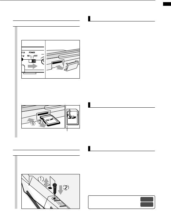
SD card installation
The R24 saves recording data and settings on SD cards.
To protect your data, turn the power off before inserting or ejecting a card.
An SD card is necessary for recording.
Turn the power OFF beforehand (ordinary use)
1 Turn the POWER OFF and detach the cover of the SD card slot.
2 Insert an SD card that is not write-protected into the slot completely.
To eject, push the card in first .
Unlock the write-protection
NOTE
•If you want to change the SD card while the power is ON, follow special procedures (see P101).
•When inserting or removing an SD card, always turn the power OFF. If you do so when the power is ON, recording data might be lost.
•If you cannot insert a card into the slot, you might be trying to insert it in the wrong direction or upsidedown. Try again with the correct card orientation. If you force the card in, you might break it.
•If an SD card was previously used with a computer or a digital camera, you must format it in the R24 before using it.
•If no SD card is inserted, the REC key will not function in Recorder Mode.
If one of these messages is shown
•“No Card”: No SD card is detected. Make sure an SD card is inserted properly.
•“Card Protected”: The SD card write-protection lock is closed, preventing rewriting. To release it, slide the switch away from the lock position.
Preventing unwanted removal of an SD card
Remove the screw near the slot, and screw it into the hole in the SD card cover.
HINT
•This unit can use SD cards with capacities of 16 MB~2 GB, as well as 4~32 GB SDHC cards.
•You can check the most recent information about compatible SD cards on the ZOOM website. http://www.zoom.co.jp
|
Ref: SD CARD>EXCHANGE |
P101 |
|
SD CARD>FORMAT |
P102 |
|
|
installation card SD
12
unit the Powering
Powering the unit
Use the included AC Adapter, which is designed for the unit, or six AA batteries (sold separately) to power the unit.
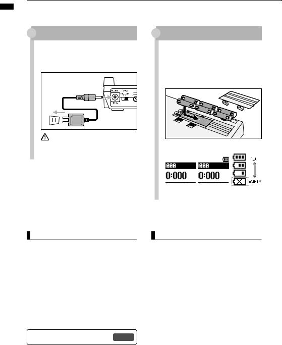
Using ordinary power (included AC adapter)
1 Make sure that the power is OFF, and then plug the included AC adapter into the back of the unit.
Always use the included ZOOM AD-14


 AC adapter, which is designed for use with the unit. Using any other adapter could damage the unit.
Using batteries
1 Turn the power OFF and open the battery case cover on the bottom of the unit.
2 Installcover. the batteries and close the
Battery indicator on screen |
Battery power |
|
No indicator |
Indicator on |
status |
|
||
AC adapter |
Batteries |
|
Batteries must |
in use |
in use |
|
|
|
|
be changed. |
|
|
|
Power will |
|
|
|
turn off. |
|
HINT
Power supply from USB
If the POWER switch is set to OFF, connecting the unit to a computer with a USB cable makes the unit start-up automatically with power supplied by USB.
In this state, functions are different from when the POWER switch is ON. The unit can be used only as an SD card reader or as an audio interface.
•When using the unit as an audio interface, if supplying phantom power, we recommend that you use the AC adapter.
Ref: Setting the battery type |
P103 |
NOTE
•Always turn the power OFF when you open/close the battery cover or plug/unplug the AC adapter. Doing so when the power is ON might cause recording data to be lost.
•The unit can use alkaline of NiMH batteries. The approximate lifetime for alkaline batteries is about
4.5 hours.
•Replace the batteries when "Low Battery!" is shown. Turn the POWER switch to OFF immediately and install new batteries or connect the included AC adapter.
•Set the battery type to increase the accuracy of the battery indicator.
13
Turning the power on & off/Date & time setting
Follow these precautions for starting-up and shutting down the unit.
Follow these instruction to set the date and time for files and data.
Turning the power on & off
1.Make sure all the equipment is OFF.
2.Insert an SD card into the R24. Confirm that the power, the instruments and the monitoring system (or stereo headphones) are correctly connected.
Turn the power ON to start the unit
1
Slide to ON
2 |
Then turn the power ON for connected |
||||||
|
|
||||||
|
|
instruments and for the monitoring |
|||||
|
|
system in that order. |
|||||
|
|
|
|
|
|
|
|
|
|
|
the power OFF to shut down the unit |
||||
|
|
|
|
|
|
|
|
1 |
|
|
|
|
|
|
|
|
|
|
|
|
|
||
|
|
|
|
|
|
|
|
|
|
|
|
|
|
|
|
|
|
Slide to OFF |
|||||
NOTE
•Before turning the POWER ON, turn down PHONES and OUTPUT controls and volume on monitoring systems and other connected devices.
•If no power is supplied to the unit for more than a minute, the DATE/TIME setting will be reset to its initial value.
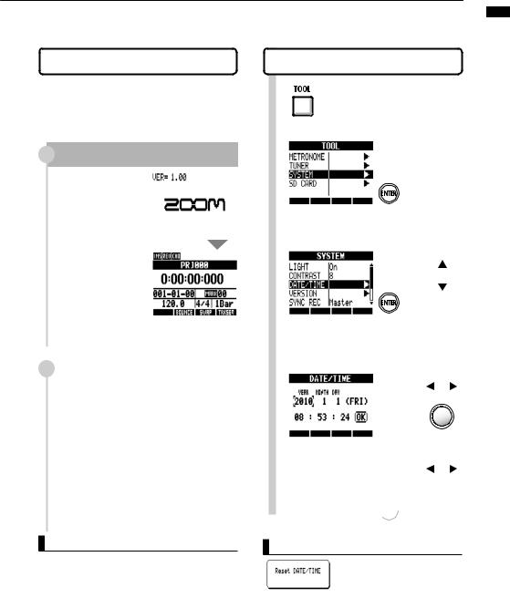
Setting the date and time |
|||
TOOL>SYSTEM>DATE/TIME |
|
||
1 |
Press |
|
|
2 Select SYSTEM. |
Change menu |
||
|
|
Press |
|
3 Select DATE/TIME. |
Change menu |
||
4 |
|
Press |
|
Select the date and time units and set |
|||
|
|||
|
their values in the following order. |
||
|
YEAR > MONTH > DAY > 00:00:00 |
||
|
|
Change |
|
|
|
unit |
|
5 Select OK.
Move cursor
 Press
Press
If this message appears
•The DATE/TIME setting has been set to its initial value. Set the DATE/TIME again.
TOOL>SYSTEM>DATE/TIME / ON/OFF POWER
14
overview operation key and Switch
Switch and key operation overview
Here we explain how to use the keys and switches of the R24.
Please look at the display for icons that show key functions.
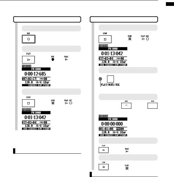
Transport section
REC key |
Functions only when tracks are |
|||
in recording standby. |
|
|||
|
|
|
||
When stopped Starts recording standby |
|
|||
Recording standby |
Ends recording standby |
|
||
During playback |
Starts recording (manual punch-in/ |
|||
punch-out) |
|
|
||
PLAY key |
|
|
|
|
When stopped |
Starts playback |
|
||
Recording standby |
Starts recording |
|
||
STOP key |
|
|
|
|
During recording |
Ends recording |
|
||
During playback |
Stops playback |
|
||
Recording standby |
Stops unit |
|
|
|
REW key |
|
|
|
|
Stopped/playback |
Rewinds |
|
|
|
|
Hold STOP and press REW to return |
|||
|
to the top of the song. |
|
||
FF key |
|
|
|
|
Stopped/playback |
Fast forwards |
|
||
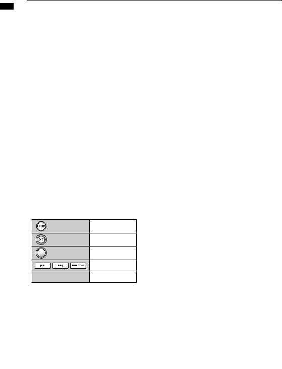
ENTER key |
|
Confirm items. |
|
|
EXIT key |
|
|
Press to go back. Hold to |
|
|
|
return to the top screen. |
||
|
|
|
||
DIAL |
|
|
Change and move among |
|
|
|
menus and numbers. |
||
|
|
|
||
|
|
|
Ref.: Mark-related keys ─ |
|
|
|
|
P33 |
|
|
|
|
Set/cancel auto punch-in/ |
|
|
|
|
out and A-B repeat |
|
Cursor appearance and |
|
|||
indication in manual |
|
|
|
|
|
|
Indications in manual |
Unit |
|
Appearance in manual |
|
|
||
Move in |
In the explanations, only the |
|
usable directions are shown |
||
menu |
||
|
Note: The cursors are used often to move up, down, left and right to choose different items. An example of their notation in the manual is shown above.
Control section
RHYTHM key |
Play, create and set rhythm |
|
patterns |
||
|
||
EFFECT key |
Set the insert and send- |
|
return effects |
||
|
||
USB key |
Use audio interface, card |
|
reader and USB memory |
||
|
||
TOOL key |
Metronome, tuner, system |
|
and SD card settings |
||
|
||
PROJECT |
Create, set and work with |
|
PROJECT key |
||
projects |
||
|
||
1-8Tr key |
|
|
|
Switch bet ween track |
|
9-16Tr key |
groups 1~8, 9~16 and |
|
17~24 (the indicator for the |
||
|
||
|
active track bank lights) |
|
17-24Tr key |
|
|
TRACK key |
Assign tracks and make |
|
settings |
||
|
||
PAN/EQ key |
Access track mixer settings |
Fader section
|
|
1/9/17~8/16/24 |
Change track status to PLAY |
|
|
||
|
|
(green), MUTE (no light) or REC |
|
|
|
TRACK status |
|
|
|
(red). Playback tracks that are |
|
|
|
keys |
|
|
|
already assigned appear orange. |
|
|
|
|
|
|
|
|
|
|
|
MASTER |
Change MASTER track status to |
|
|
PLAY (green), MASTER (no light— |
|
|
|
status key |
|
|
|
no playback/recording) or MIX |
|
|
|
|
|
|
|
|
DOWN (red). |
|
|
|
|
 Switches and controls
POWER switch |
Turns power ON & OFF |
|
|
|
|
Hi-Z switch |
Turns Hi-Z connection on/off (only |
|
for INPUT 1) |
||
|
||
MIC switch |
Turns built-in microphones on/off |
|
(signals to INPUTS 7 & 8) |
||
|
||
|
|
|
METRONOME switch |
Sets metronome output |
|
PHANTOM switch |
Turns phantom power ON & OFF |
|
|
|
|
|
|
|
GAIN control |
Adjusts input sensitivity |
|
PEAK indicator |
Lights if maximum input detected |
|
|
|
|
|
During recording, when the METRO- |
|
BALANCE control |
NOME switch is set to PHONES ONLY, |
|
use to balance the volume of the |
||
|
||
|
stereo mix and the metronome |
|
|
|
|
Level meters |
Shows recording/playback levels |
|
|
|
|
TEMPO indicator |
Flashes in time with the count |
|
|
|
15
Display information
The display shows data about projects and other elements, connection and operation status as a recorder or a computer audio-interface, available functions and various menus.
 Display and indications
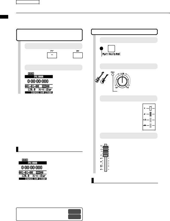
Top Screen: Shows the current project
Icon display area
|
|
|
|
|
|
|
|
|
|
|
|
|
|
|
Project name |
|||
|
|
|
|
|
|
|
|
|
|
|
|
|
|
|
Hours: minutes: seconds: |
|||
|
|
|
|
|
|
|
|
|
|
|
||||||||
|
|
|
|
|
|
|
|
|
|
|
|
|
|
|
milliseconds |
|||
Time |
|
|
|
|
|
|
|
|
|
|
|
|
A-B repeat icon |
|||||
|
|
|
|
|
|
|
|
|
|
|
|
|||||||
sig. |
|
|
|
|
|
|
|
|
|
|
|
|
|
|
|
Bar–beat–tick |
||
|
|
|
|
|
|
|
|
|
|
|
|
|
|
|
||||
|
|
|
|
|
|
|
|
|
|
|
|
|
|
|
|
Mark, mark number |
||
Tempo |
|
|
|
|
|
|
|
|
|
|
|
|
|
|
|
|
||
|
|
|
|
|
|
|
|
|
|
|
|
|
|
Global quantization |
||||
|
|
|
|
|
|
|
|
|
|
|
|
|
|
|||||
|
|
|
|
|
|
|
|
|
|
|
|
|
||||||
(BPM) |
|
|
|
|
|
|
|
|
|
|
|
|
|
|
|
|
||
Soft key
Menu screen: Shows an operation menu
Menu name or track number
Press the ENTER key to show the next menu or execute an operation
Use the DIAL to set and change values
Select items with the up and down cursor keys
 Icon display and setting keys
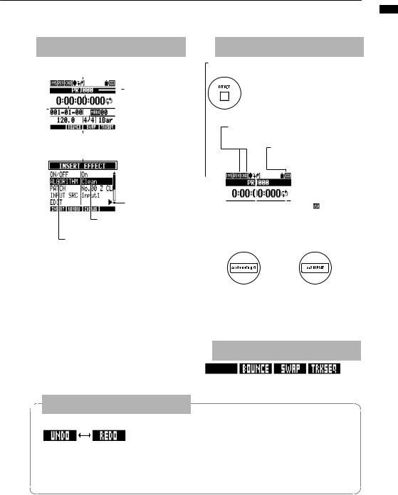
Insert effect icon – P80
ON when shown. Use key to set.
EFFECT key
Use key to open the EFFECT menu.
Send-return effect – P80
Reverb/chorus icon
ON when shown. Use key to set.
PROTECT icon – P89
If shown, project is protected and cannot be overwritten. Set using menu.
|
|
|
|
|
|
|
Battery icon – P13 |
||
|
|
|
|
|
|
|
|||
|
|
|
|
|
|
|
When shown, batteries are in use |
||
|
|
|
|
|
|
|
and their remaining charge is |
||
|
|
|
|
|
|
|
indicated by the number of bars. |
||
|
|
|
|
|
|
|
|||
|
|
|
|
|
|
|
When shown, USB power is |
||
|
|
|
|
|
|
|
in use. When nothing is shown |
||
|
|
|
|
|
|
|
the AC adapter is in use. |
||
|
|
|
|
A-B repeat icon – P32 |
|||||
AUTO PUNCHI IN/OUT |
|
|
|||||||
|
|
||||||||
icon – P29 |
|
|
|
|
|
|
|||
|
|
|
|
|
|
||||
|
|
|
|
|
|
|
|
|
|
AUTO PUNCH IN/OUT key |
A-B REPEAT key |
||||||||
Set when displayed. |
A-B points set when displayed |
||||||||
Use key to set. |
Use key to set. |
||||||||
The indications in enclosed in boxes, including F1~F5 beneath the row starting with the AUTO PUNCH I/O key, < BANK >, DIRECT, and DAW, are functions when used as a control surface in audio interface mode.
 Soft keys
information Display
 UNDO/REDO
UNDO indicator |
REDO indicator |
UNDO: Return to the state before the previous operation after (PUNCH IN/OUT) recording, BOUNCE or MIX DOWN (to MASTER TRACK)
REDO: Reverse the UNDO operation
The functions of the soft keys appear at the bottom of the display. Press the key under the indication to use that function.
When indicators are shown
After recording and certain other operations, “UNDO” is shown. After pressing the UNDO soft key, “REDO” is shown. Press the soft key to execute.
NOTE
•Undo only works on tracks with recorded audio data
•Only the previous operation can be undone.
Any earlier operations cannot be undone.
16
project new a flow/Creating recording R24
Recording preparations
R24 recording flow/Creating a new project
With the R24, you can use multitrack recording to create a complete work of music.
Create a new project for each song that you make.
Recording preparations
Connecting instruments
Project and track settings
Create a new project
Select the INPUTS and the recording tracks Set stereo links
Change track status (recording, play, mute)
Adjust input sensitivity using the GAIN controls
Performance preparation
Set metronome including pre-count
Set and use tuner
Recording the first tracks
Recording standby—record—stop
Recording more tracks
Overdubbing
Playback of already recorded tracks
Overdubbing
Record standby—Record—Stop
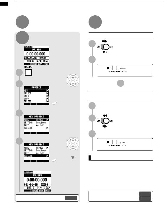
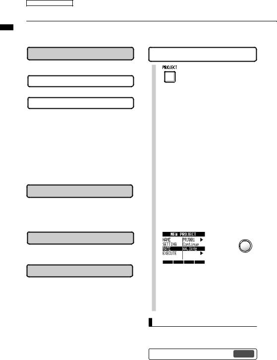
Create a new project
PROJECT>NEW
1 |
Press |
|
2 Select NEW. |
Change menu |
|
3 |
Press |
|
Confirm the project NAME. |
|
|
|
|
|
|
|
Change menu |
Select whether to CONTINUE |
Change menu |
4 using the previous settings. |
|
|
Change |
5 Set the sampling RATE. |
setting |
Change menu |
|
|
Change |
|
setting |
6 Select EXECUTE. |
Change menu |
Press |
|
HINT
Ref: Creating a new project |
P90 |
17
Recording preparations
Connecting instruments/Making mono settings
Make settings for instruments such as high impedance guitars, line-input synths, the built-in mics and mics that use phantom power as well as for stereo and mono input sources.
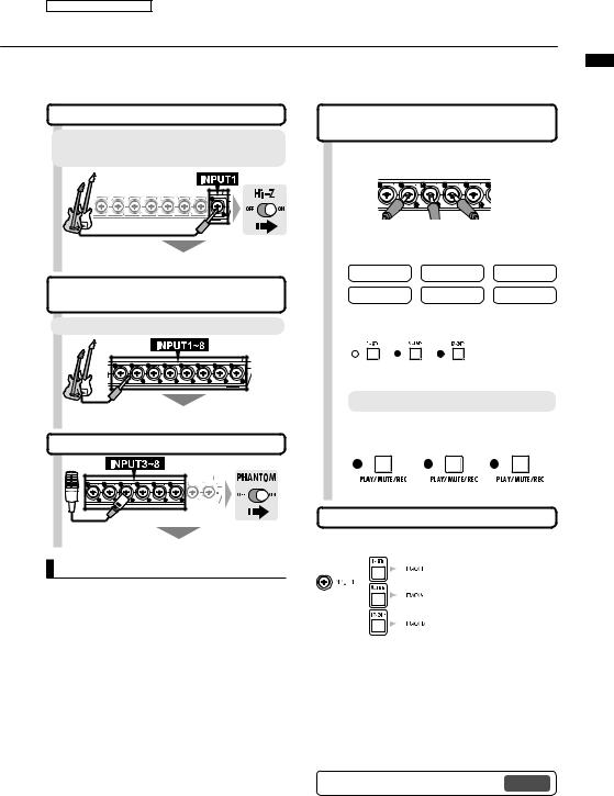
Connecting passive-type guitars
Connect the high impedance instrument to INPUT 1, and the turn the Hi-Z switch ON.
Connecting low-impedance instru-
Connect low impedance instruments to any INPUT 1~8.
Signals to any INPUT 1~8
Using phantom power
Supply phantom power to the connected mic
NOTE
•Turn the PHANTOM switch ON to provide +48 V power to INPUTS 3~8.
•In order to reduce battery consumption by the use of phantom power, it can be turned off to INPUTS 3, 4, 7 and 8, and the voltage can be reduce to +24 V (Ref. P104).
•Use the fader that is in line with the INPUT jack. The signal from INPUT 1 goes to track 1,9 or 17.
•To use tracks 9~16 or 17~24 press the 9~16Tr or
17~24Tr key to switch the fader assignment.
•Depending on the insert effect selection, the output can change.
•Create one stereo file from two faders by using the stereo link setting.
Assign INPUT 1~8 connections to tracks 1~24
1 Connect instruments and mics.
INPUTS 1~8
2 Make settings for instruments, built-in mics, stereo tracks, etc.
|
Hi-Z |
|
PHANTOM |
MIC |
|
Stereo |
|
Mono x 2 |
Mono |
3 |
Select the bank of tracks. |
|||
|
|
|
Assign faders to |
|
|
|
|
|
tracks 1~8, 9~16 |
|
Tracks |
Tracks |
Tracks |
or 17~24 |
|
|
|||
4 |
1~8 |
9~16 |
17~24 |
|
Change the status of the connected inputs. |
||||
|
Press the status key of a track |
|||
|
1–2 times to turn its red light on. |
|||
 When red, recording is possible
Set the tracks to receive inputs
Press the 1-8Tr, 9-16Tr or 17~24Tr key to set the bank of tracks that will record the inputs.
|
|
|
|
|
|
|
|
|
|
|
|
|
|
|
|
|
|
|
|
|
|
|
|
|
|
|
|
|
|
|
|
|
|
|
|
|
|
|
|
|
|
|
|
|
|
|
|
|
|
|
INPUT |
|
|
|
|
|
|
|
|
|
|
TRACK |
|
||||
|
|
|
|
|
1~8Tr key active |
9~16Tr key active |
17~24Tr key active |
|||||||||
1 |
|
|
1 |
|
|
|
|
9 |
17 |
|||||||
2 |
|
|
2 |
|
|
|
|
10 |
18 |
|||||||
3 |
|
|
3 |
|
|
|
|
11 |
19 |
|||||||
4 |
|
|
4 |
|
|
|
|
12 |
20 |
|||||||
5 |
|
|
5 |
|
|
|
|
13 |
21 |
|||||||
6 |
|
|
6 |
|
|
|
|
14 |
22 |
|||||||
7 |
|
|
7 |
|
|
|
|
15 |
23 |
|||||||
8 |
|
|
8 |
|
|
|
|
16 |
24 |
|||||||
Ref: Stereo setting |
P19 |
|||||||||||||||
settings mono instruments/Making Connecting
18
keys status & settings instruments/Stereo Connecting
Recording preparations
Connecting instruments/Stereo settings & status keys
To make a stereo recording, set a stereo link for adjacent odd and even-numbered tracks and record on them. Use the status keys to send input signals to recording tracks.
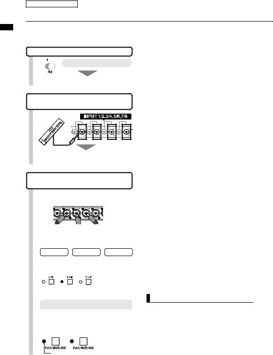
Using the built-in mics

 Turn the MIC switch ON
Signals to INPUTS 7/8
Connecting line input instruments (stereo connection)
Use INPUTS 1/2, 3/4, 5/6 and 7/8 as pairs. Input left signals to odd-numbered tracks and right signals to even numbered tracks.
Assign INPUTS 1–8 to tracks 1–8, 9–16 or 17–24.
1 |
Connect instruments and mics. |
|||
|
INPUT1~8 |
|
||
|
Make settings for instruments, |
|||
2 built-in mics, stereo tracks, etc. |
||||
|
Stereo |
|
Mono x 2 |
MIC |
3 |
Select the track bank. |
|
||
|
|
Assign faders to tracks |
||
|
|
|
1~8, 9~16 or 17~24 |
|
|
Tracks |
Tracks |
Tracks |
|
|
1~8 |
9~16 |
17~24 |
|
4 |
Set the status of the connected inputs. |
|||
Press a status key of the linked tracks one or two times to turn both lights red.
NOTE
•Use the fader that is in line with the INPUT jack. The signal from INPUT 1 goes to track 1, 9 or 17.
•To use tracks 9~16 or 17~24, press the 9~16Tr or
17~24Tr key to switch the fader assignment.
When red, recording is possible
19
Recording preparations
Stereo link
Enable a stereo link for tracks in advance of recording to create a stereo file when recording. You can also assign stereo files.
Status keys and track indicators
Press a status key to set the role of a track fader and change the color of the track indicator light. The track indicator colors show the status as follows.
REC |
|
PLAY |
|
MUTE |
Record ready |
Playback ready |
|
Sound disabled |
|
|
indicators (1~24) |
|
|
|
|
→ |
Press |
→ |
Press |
REC |
→ |
PLAY |
→ |
MUTE |
Lit red |
→ |
Lit green |
→ |
Unlit |
|
Track indicator (MASTER) |
|
||
Press |
→ |
Press |
→ |
Press |
MASTER |
→ |
MIX DOWN |
→ |
PLAY |
Unlit |
→ |
Lit red |
→ |
Lit green |
HINT
•In order to send the signal from an INPUT to a recording track, press its status key 1–2 times until the track indicator lights red.
•To use two inputs press both status keys to connect both to tracks.
•To create one stereo file when recording two tracks set a stereo link.
•If the MASTER track is set to PLAY, all other tracks will be set to MUTE (no sound).
Stereo link
PAN/EQ>STEREO LINK
2 Select a track.
Change tracks
3 Select ST LINK.
Change menu
4 Select On.
The tracks that are joined with a stereo link are shown.
HINT
•The track pairs than can be joined with stereo link are: 1/2, 3/4, 5/6, 7/8, 9/10, 11/12, 13/14, 15/16, 17/18, 19/20, 21/22 and 23/24
•Stereo link changes the setting from two mono tracks to one stereo track.
•Whatever track number you choose, an adjacent track will be linked. You cannot change these combinations.
•To adjust the volume of a pair of tracks joined by stereo link, use the odd number fader. The even number fader has no effect.
•The pan parameter of a pair of tracks joined by stereo link can be used to adjust their relative volume balance.
•Stereo files can be assigned to tracks joined by stereo link. The left channel is sent to the odd track and the right is sent to the even track.
link Stereo
20
tempo the Setting
Recording preparations
Setting the tempo
Set the tempo for the music. The tempo is saved for each project.
Changing the tempo |
|
|
1 Press |
beneath |
. |
2 |
Use the dial to change the value. |
|
|
||
Tap  beneath
  repeatedly.
The average pace will be set as the tempo value.
|
Tempo |
Range |
|
40.0~250.0 |
Default value : 120.0 |
21
Recording preparations
Preparing a rhythm track
The R24 has a sampler function that allows loops to be played back on each track. Here, we assign a rhythm pattern that is built-in to the R24 to a track as a guide rhythm.
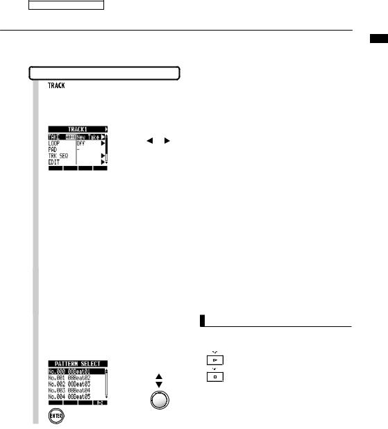
Assignment to a track
1 Press
Press
2Select the track to assign.
Select track
3 Select TAKE.
Change menu
Press
4 Select PATTERN to use a rhythm pattern.
Change menu
|
Press |
5 |
the rhythm pattern. |
Select a file or |
|
pattern |
Press
HINT
• You can also play the selected audio file or pattern.
Play
Stop
•If rhythm patterns are assigned to multiple tracks and played back simultaneously, or patterns with numerous note-on events are played, they might not all play as expected due to the maximum polyphony limitation of the unit.
•You can assign the loop files on the included USB memory (ref. P49).
•In Step 5, you can change the order of the pattern list.
Press the A-Z soft key to list the patterns in alphabetical order.
Press the No. soft key to list the patterns in numerical order.
track rhythm a Preparing
22
track first the Recording
Track recording
Recording the first track
After connecting instruments and completing recording preparation, ready the recorder and start recording the first track.
Starting from the Top Screen of a new project
1 Return the counter to the beginning
Press and hold  and press
  to return to the beginning.
Top Screen
Counter at head position
(mark 00).
HINT
• The Top Screen display of a new project
Counter at head position
(mark 00).
•After setting the input (Step 5 and after), you can process input signals with the insert effect.
Ref: New project creation |
P90 |
Insert effect |
P81 |
|
2 Arm the track for recording.
Press 1-2 times until the track light turns red.
|
When red, recording is possible |
|
3 |
Adjust the input sensitivity GAIN. |
|
|
|
Adjust the |
|
|
input level. |
Make |
|
|
noise! |
Should light briefly when the |
|
4 |
|
volume reaches maximum |
Adjust the recording level. |
||
If an insert effect is applied to an INPUT, adjust the patch level, for example, so that the red indicator (0dB) on the
level meter does not light.
5 Adjust the monitoring system.
Use the fader for the recording track to adjust the monitoring level of the instrument being recorded (INPUT 1 is track 1, 9 or 17).
NOTE
Red lights on PEAK indicators and level meters
A PEAK indicator turns red when the signal exceeds the maximum detectable level of 0 dB, resulting in input clipping. The red indicator on a level meter means that the signal being recorded (signal after passing through the insert effect) is clipping. If clipping happens, the recorded sound will be distorted. You should reduce the recording level.
23
Recording the first track
6 Start recording standby.
Press  red
red
7 Start recording.
Press |
Lit red |
Lit green |
|
Counter starts |
|
8 Stop recording.
Press |
Lit green |
Unlit |
|
|
The counter stops moving, but does not return to 0.
HINT
• Press the UNDO soft key to cancel the operation.
Recording again
•If you record again on the same track, the previous recording will be overwritten.
•There are two ways to make a new recording or re-record.
•Press the UNDO soft key to undo the recording.
•Use the TRACK > TAKE > FILE menu to assign the track used for recording to a "New Take" (Ref. P25).
Playing back the recorded track
9 Press stop (if you have not already). |
|
|
Press |
Lit |
Unlit |
|
green |
|
|
Counter stops |
|
10 Play the track.
Press on the track to be played 1-2 times until lit green
|
When green, the track is |
11 |
ready for playback |
Return the counter to the beginning. |
Press and hold  and press
  to return to the beginning.
12 |
track. |
|
|
||
13 |
Press green |
|
. |
||
|
Press green
•If the REC MODE is set to Overwrite, recorded audio files on tracks will be overwritten when new recordings are made. Be careful when returning the counter to the beginning and recording again. Set the REC MODE to Always New if you do not want to overwrite recordings.
•When set to play, the recording currently on the track will be played.
track first the Recording
24
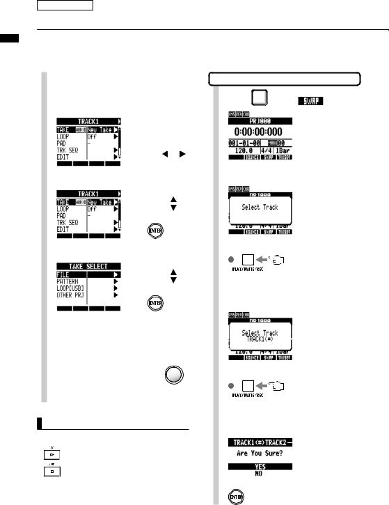
take playback the Changing
Track recording
Changing the playback take
You can assign audio files to tracks freely. By recording multiple takes of vocals, guitar solos and other parts in different files, you can later select the best take.
1 Press
Press
2 Select the track to assign.
|
|
Select track |
3 Select TAKE. |
Change menu |
|
|
|
Press |
4 For an audio file, select FILE. Change menu |
||
|
|
Press |
5 |
Select the desired audio file. |
|
|
Select the file |
|
|
or pattern |
|
 Press
Press
HINT
•also play the selected audio file.
Play
Stop
•Files that are already assigned to tracks have an
*to the left of their names.
Switching two tracks (SWAP)
1 Press |
beneath |
. |
2 Select the first track to swap.
Indicators blink orange on tracks that can be selected. Press the status key to select a track.
|
|
Selectable: blinking orange |
|
|
||
|
|
Selected: lit orange |
|
|
||
3 Select the second track to swap. |
||||||
|
|
|
|
|
|
Already selected |
|
|
|
|
|
||
|
|
|
|
|
|
track |
Indicators blink orange on tracks that can be selected. |
||||||
Press the status key to select a track. |
||||||
|
|
Selectable: blinking orange |
|
|
||
|
|
|
|
|||
|
|
Selected: lit orange |
|
|
||
4 Swap the tracks. |
|
|
Tracks to be swapped |
|||
|
|
|||||
|
|
|
|
|
|
Move cursor |
Press
25

NOTE
The swap function switches two tracks, including the assigned files, track sequence data and all track parameter information.
take playback the Changing
26
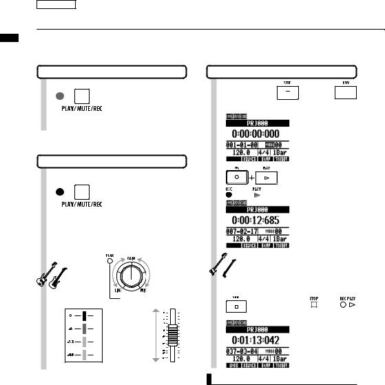
tracks additional Recording
Overdubbing
Recording additional tracks
After recording the first track, you can record additional tracks while playing back already recorded audio. Preparations for recording are the same as for the first track, but you can also set recordings to play on different tracks.
Playing already recorded tracks
1 |
|
Press 1-2 times until the |
|
indicator lights green for |
|
|
|
tracks to be played |
|
|
back. |
|
|
Playback-ready when green |
|
|
|
Preparing to record more tracks |
||
2 |
|
Press for all recording |
|
tracks 1-2 times until the |
|
|
light turns red. |
|
|
|
is possible |
|
|
|
3 Adjust the input level. |
||
Make noise!
Red
Orange
Orange
Green
Input sensitivity
Briefly lights when the volume reaches maximum.
Set the level so that at maximum volume the red light (0 dB) does not light.
Recording level |
Monitoring system |
Start and stop recording
4 Press and hold  and press
  to return to the beginning.
5 |
Press REC and PLAY |
|
|
|
in order to start |
Lit red |
Lit green recording. |
|
Counter starts |

 Play!
Play!
6 |
|
Press to stop. |
|
green |
|
|
|||
|
|
|
||
|
|
The counter stops moving, |
||
|
|
but does not return to 0. |
||
HINT
•If you want to use a track that has already been recorded on for a later recording, assign the recorded file to another track, and make the target track empty. Refer to "Changing the playback take" (P25).
You can also swap recorded tracks with unrecorded tracks.
Do this, when creating a second guitar track using Hi-Z, for example.
27
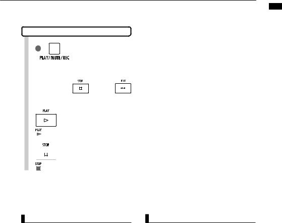
Playback all tracks |
||||||||
1 |
|
|
|
|
Press 1-2 times until the |
|||
|
|
|
|
indicator lights green for |
||||
|
|
|
|
|
tracks to be played |
|||
|
|
|
|
|
back. |
|||
|
|
|
Playback-ready when green |
|||||
|
|
|
||||||
Press and |
|
|
and |
|
||||
|
|
|
||||||
2 to return to the |
beginning. |
|||||||
3 |
|
|
|
|
Press to start playback. |
|||
|
|
|
|
|
||||
|
|
|
|
|
|
|
|
|
green
4  Press to stop playback.
green
tracks additional Recording
NOTE
•When you move files on tracks, confirm that no files are assigned to the tracks to be recorded (“New Take”).
If there is a file assigned to a track, that recording will be overwritten by new recording.
•If the REC MODE is set to Overwrite, recorded audio files on tracks will be overwritten when new recordings are made. Be careful when returning the counter to the beginning and recording again. Set the REC MODE to Always New if you do not want to overwrite recordings.
•When a track is play-enabled, the file on it will play back.
HINT
•If you are recording on a different track than the first track, there is no need to move or swap the first track.
•If you want to record a new file, set that track to
New Take.
28
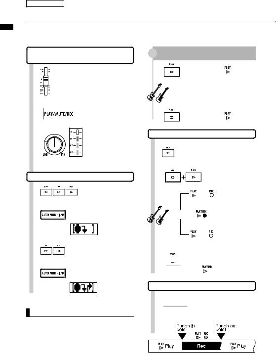
out-in/punch-
Re-recording
Automatic punch-in/punch-out
Punch-in and punch-out allow you to re-record a single part of a recorded file. You can -out) points in advance to start and stop
Prepare the track that you want to punch-in/punch-out
1 

 Raise the fader on the track


 you want to re-record
2 

When red,
3 


Press 1-2 times until lit red
possible
Adjust the recording level and the GAIN to be the same as the already recorded part.
Set the punch-in/out points |
||
4 |
Locate the starting |
|
|
||
|
position (punch-in |
|
5 |
point) |
|
Press to set the punch-in point |
||
|
||
|
Appears on |
|
6 |
display |
|
Locate the ending position |
||
|
||
7 |
(punch-out point) |
|
Press to set the punch-out point |
||
|
||
|
Appears on |
|
|
display |
|
NOTE
•Once you set auto punch-in/out point, you cannot change them. Cancel and set them again.
•If the REC MODE is set to Always New, a new file will be recorded.
|
Rehearse |
|
|
|
1 |
Press to start |
Lit |
||
playback. |
||||
|
||||
|
When the punch-in point is passed, the track is |
|||
|
automatically muted. |
|
|
|
|
Perform (not recording) |
|
||
|
When the punch-out point is passed, the track is |
|||
2 |
automatically unmuted. |
|
||
Press to stop |
Unlit |
|||
|
||||
|
playback. |
|
||
Re-recording: punch-in/punch-out |
||||
8 |
Locate to before the |
|
||
punch-in point. |
|
|||
9 |
|
Press REC and PLAY in |
||
|
order to start recording. |
|||
|
Lit |
Blinks |
Not recording |
|
|
Pass the punch-in point |
|
||
|
Perform |
Lit |
Recording |
|
|
Pass the punch-out point |
|||
|
Lit |
Blinks |
Not recording |
|
10 Press to stop recorder.
 Unlit
Unlit
Cancel punch-in/out
11 Press
Press
Indicators disappear from display
Re-recorded part
29
 Loading...