


 Loading...
Product Transition Guide
GPD 515/G5 to F7
PL.F7.02.Transition Guide

Product Transition Guide
GPD515/G5 to F7
NOTICE
The information contained within this document is the proprietary property of Yaskawa Electric America, Inc., and may not be copied, reproduced or transmitted to other parties without the expressed written authorization of Yaskawa Electric America, Inc. No patent liability is assumed with respect to the use of the information contained herein. Moreover, because Yaskawa is constantly improving its high-quality products, the information contained in this document is subject to change without notice. Every precaution has been taken in the preparation of this document. Nevertheless, Yaskawa assumes no responsibility for errors or omissions. Neither is any liability assumed for damages resulting from the use of the information contained in this publication.
__________________________
PL.F7.02.TransitionGuide 6/5/06
Page 2 of 40
Yaskawa Electric America, Inc

|
Product Transition Guide |
|
Table of Contents |
Feature Overview.................................................................................................................... |
5 |
GPD515/G5 to F7 Feature Differences................................................................................... |
6 |
Digital Operator Comparison................................................................................................... |
8 |
Front Cover & Cooling Fan Comparison ................................................................................. |
9 |
Main Control PCB Comparison ............................................................................................. |
10 |
Nameplate/ Labeling Differences .......................................................................................... |
11 |
Physical Dimensions............................................................................................................. |
12 |
GPD515/G7 to F7 Terminal Comparison .............................................................................. |
13 |
Network Communications ..................................................................................................... |
16 |
Details on New F7 Features & Functions.............................................................................. |
17 |
New ”Heavy Duty” and “Normal Duty” ratings for the F7....................................................... |
18 |
Appendix 1 ............................................................................................................................ |
19 |
Output Amps, Carrier and Overload Comparison ................................................................. |
20 |
240V Heavy Duty Ratings (C6-01=0)............................................................................. |
20 |
480V Heavy Duty Ratings (C6-01=0)............................................................................. |
21 |
240V Normal Duty Ratings (C6-01=2) ........................................................................... |
22 |
480V Normal Duty Ratings (C6-01=2) ........................................................................... |
23 |
Mouting Hole Data ................................................................................................................ |
24 |
Heat Loss Data ( F7 and GPD515/G5) ................................................................................. |
25 |
Appendix 2 – Parameter Differences .................................................................................... |
27 |
__________________________
PL.F7.02.TransitionGuide 6/5/06
Page 3 of 40
Yaskawa Electric America, Inc

Product Transition Guide GPD515/G5 to F7
Page Intentionally Left Blank
__________________________
PL.F7.02.TransitionGuide 6/5/06
Page 4 of 40
Yaskawa Electric America, Inc
Product Transition Guide
GPD515/G5 to F7
Feature Overview
This document details differences between the GPD515/G5 and F7 product to assist in product transition and new product introduction.
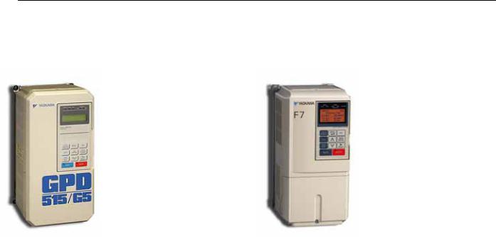
GPD515/G5 Drive
The GPD 515/G5 drive is a generalpurpose drive, intended for a broad range of applications in Industrial Automation. Accordingly, it is available with many choices of I/O, communications, and software. It is available in constant torque ratings, 3/4 to 500 horsepower. The G5 HHP is available to 1500 HP.
F7 Drive
The F7 drive is positioned as the Industrial Workhorse. It is the best choice in a single drive format for every conventional industrial drive application in its horsepower range of ½ to 500 hp. It is dual rated to enable best choice for Normal (Variable Torque) machine loads and Heavy Duty (Constant torque) machine loads.
F7 Features & Functions
•Analog outputs with new 4-20ma selection and 10 bit resolution.
•Improved input voltage specification.
•Enhanced digital operator with copy function
•Simplified parameter menu navigation
•New LCD contrast adjustment
•New PID sleep function
•More preset speed selections
•More versatile PNP/NPN sinking /sourcing I/O
•More relay outputs
•More versatile analog outputs
•New pulse I/O
•New quick disconnect terminal I/O
•New cooling fan on/off control and elapsed time and cassette replacement design
•New 12-pulse diode bridge
•Built-in RS485 communication with self test mode
•New drive enable input selection
•New automatic derating based on ambient temperature setting
•New motor temperature analog input
•New motor overheat alarm outputs
•Addition under torque selections
•New kWh and mWh and heat-sink temp monitors
•New Bi-directional speed search
•Enhanced fault storage (Qty. 10 faults)
•Improved Energy Savingsmanual/automatic modes
•High Slip Braking
•Improved Auto-Tuning Functions
F7 Performance
•Auto-tuning 3-Methods (R1/Static/Dynamic)
•Static no load auto-tuning offers same torque accuracy performance as dynamic auto-tuning at base speed & below
•Dual rating: Heavy Duty 150% 60 secs/ Normal Duty 110% 60 secs
•DC input compatible (all models) simplified connection to DC power, removal of internal DC bus choke not required.
__________________________
PL.F7.02.TransitionGuide 6/5/06
Page 5 of 40
Yaskawa Electric America, Inc

Product Transition Guide
GPD515/G5 to F7
GPD515/G5 to F7 Feature Differences
Feature |
Item |
Yaskawa GPD515/G5 |
Yaskawa F7 |
|
HP Range |
200V |
230V 0.5 to 150HP 1 |
240V 0.5 to 150HP (ND)2 |
|
|
400V |
460V 0.5 to 400HP 1 |
480V 0.5 to 500HP (ND) |
|
|
600V |
2 to 200HP |
N/A |
|
|
|
|
|
|
Input Voltage |
Rated Voltage |
3-phase, 200-230Vac |
3-phase, 200-240Vac |
|
|
3-phase, 380-460Vac |
3-phase, 380-480Vac |
||
|
|
|||
PWM Carrier Frequency |
Range |
See Appendix 1 |
See Appendix 1 |
|
Max. Output Frequency |
Hz |
400Hz (800Hz optional) |
300Hz (HD) 400Hz (ND) |
|
|
1000 Hz optional |
|||
|
|
|
||
Keypad Design |
Display |
2 Line x 16 Character LCD |
5 Line x 16 Character LCD |
|
|
Copy Function |
No |
Yes |
|
Digital Input Terminal |
NPN/PNP |
NPN |
Switchable NPN/PNP |
|
Digital Output Terminal |
Open Collector |
2 |
0 |
|
|
Relay Output |
1 x Form A, 1 x Form C |
3 x Form A, 1 x Form C |
|
Analog Output |
|
2 channels |
2 channels |
|
|
Output Level |
with independent level selections |
||
|
0-10V or –10V to +10V |
0-10V (10 bit plus sign) or |
||
|
|
(9 bit plus sign) |
–10-+10V or (10 bit plus sign) or |
|
|
|
|
4-20ma (10 bit plus sign) |
|
Pulse Input |
Qty. |
0 |
1 |
|
|
Input Freq. |
Not Available |
1-32kHz |
|
Pulse Output |
Qty. |
0 |
1 |
|
|
Output Freq. |
Not Available |
0-32kHz |
|
Quick Disconnect |
Type |
No |
Yes (Phoenix) |
|
Terminals |
||||
|
|
|
||
Auto Tuning |
Rotating/Stationary |
Rotating |
Rotating/Stationary/ |
|
|
Primary Resistance |
|||
|
|
|
||
Preset Speeds |
Qty. |
8 |
17 |
|
Speed Search |
Bi/Uni-Directional |
Uni-Directional |
Bi-Directional |
|
|
Method |
Current |
Current/ Speed |
|
Auto Restart |
Time Between |
180.0 sec continuous |
0.0 – 5.0 sec |
|
|
Attempts |
(not selectable) |
(selectable) |
|
Energy Savings Mode |
Man/Auto |
Manual |
Man/Auto |
|
DC Injection Function |
At Start/At Stop |
At Start/At Stop |
At Start/At Stop +HSB during stop |
|
Braking Function |
DB Transistor |
Built-in to 10HP (230V) |
Built-in to 25HP |
|
|
Built-in to 25HP (460V) |
|||
|
|
|
||
|
Special |
No |
High Slip Braking |
|
Cooling Fan On/Off |
Power/Run |
No |
Run Based |
|
Control |
||||
|
|
|
||
Timer Function |
On/Off Delay |
On/Off Delay (0-25.5 sec) |
On/Off Delay (0-3000 sec) |
|
Fault Code Additions |
- |
n/a |
10 additional |
|
Torque Limit / Current |
|
Stall Prevention |
Stall Prevention |
|
Limit / |
|
During Accel/Run/Decel (V/F) |
During Accel/Run/Decel (V/F) |
|
Stall Prevention |
- |
Torque Limit in 4 Quadrants |
Torque Limit in 4 Quadrants (Vector) |
|
|
|
(Vector) |
Software current limit |
|
|
|
|
(HD=150%/ND=120%) |
1Larger G5 models available by HHP modular design.
2HD=Heavy Duty, ND=Normal Duty
__________________________
PL.F7.02.TransitionGuide 6/5/06
Page 6 of 40
Yaskawa Electric America, Inc

Product Transition Guide GPD515/G5 to F7 Feature Differences
Feature |
Item |
Yaskawa GPD515/G5 |
|
Harmonic Counter |
- |
Filters/Reactors (Options) |
|
Measures |
|||
|
|
||
|
Built-In DC Bus |
230Vac: 18.5-75kW |
|
|
Reactor |
460Vac: 18.5-160kW |
|
Ambient Temperature |
|
|
|
|
ºC |
-10ºC ~ +40ºC (IP21) |
|
|
-10ºC ~ +45ºC (IP00) |
||
|
|
||
|
|
|
|
Storage Temperature |
ºC |
-10ºC ~ +60ºC |
|
Network Communications |
Standard |
Modbus RTU via RS232 |
|
|
|||
|
|
|
|
|
|
RS232 to RS485, DeviceNet, |
|
|
Optional |
ProfibusDP, Interbus-S, Lonworks, |
|
|
|
ModbusPlus, CanOpen,CC-link |
|
Unique Feature / Function |
- |
|
|
Split front cover |
- |
No |
|
Modular heat sink fan |
- |
No |
|
I/O Terminal Arrangement |
- |
Numerically labeled |
|
Mounting Conversion Kit |
|
Yes (G3 to GPD515/G5) |
Yaskawa F7
12 Pulse: 30HP and Above
Filters/Reactors (Options) 240Vac: 22-110kW 480Vac: 22-300kW -10ºC ~ +40ºC (IP21) -10ºC ~ +45ºC (IP00) (Automatic OL protection curve
based on ambient temperature setting of L8-12)
-20ºC ~ +60ºC Modbus RTU
via terminal I/O RS485/422 DeviceNet, Profibus-DP, Interbus-S, ControlNet, Ethernet, CC Link, CanOpen
HSB – High Slip Braking
Yes
Yes
Alpha Numeric labels No
__________________________
PL.F7.02.TransitionGuide 6/5/06
Page 7 of 40
Yaskawa Electric America, Inc
Product Transition Guide
GPD515/G5 to F7
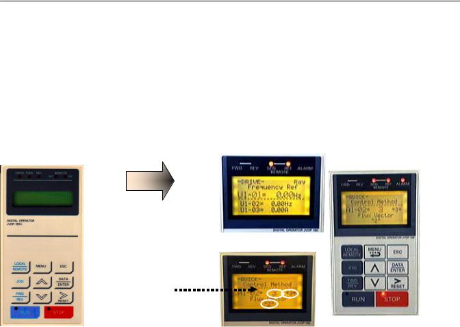
Digital Operator Comparison
•Enhanced LCD operator with built-in copy function and parameter verify for F7
•Optional LED operator available for F7
•LCD contrast adjustment
•Simplified parameter grouping for easier navigation and set-up
•The F7 has a similar key layout and parameter structure as GPD515/G5 for “ease” of programming
GPD515/G5 Operator |
New F7 Operator |
LCD Display |
LCD Backlit Display |
2 Line x 16 Characters |
5 Line x 16 Characters |
Frequency Ref
U1-01 = 0.00Hz
F7 operator indicates:
•Present selection
•Factory default setting
•Programmed value
•F7 copy keypad is capable of uploading all of the parameter settings from the F7 drive memory. o Upload of GPD515/G5 parameters to F7 not possible at this time
o F7 Drives must have the same software version, model, and control mode to copy parameters.
•A Quick Start menu is added to aid in simple start-ups.
•The Quick Start menu consists of 26 parameters. The Advanced menu is the other menu choice.
Simplified Menu Structure in F7:
GPD515/G5 |
F7 |
Operation |
Operation “DRIVE” |
— |
Quick Setting “QUICK” |
Programming (Quick Start, Basic, Advanced) |
Programming “ADV” |
Modified Constants |
Modified Constants “VERIFY” |
Auto-Tuning |
Auto-Tuning “A.TUNE” |
Initialize |
|
__________________________
PL.F7.02.TransitionGuide 6/5/06
Page 8 of 40
Yaskawa Electric America, Inc
Product Transition Guide
GPD515/G5 to F7
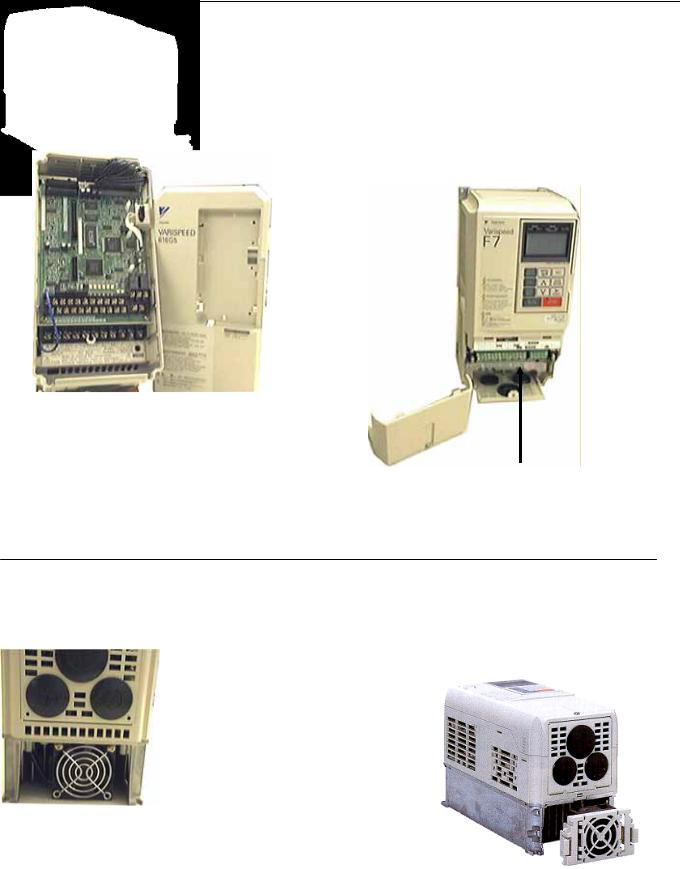
Front Cover & Cooling Fan Comparison
GPD515/G5 Front Cover (not split) |
F7 - New Split Front Cover |
||||
|
|
|
The F7 comes with a split cover to allow |
||
|
|
|
terminal only access. Limits exposed control |
||
|
|
|
PCB or power structure during wiring. |
||
|
|
|
|
|
|
|
|
|
|
|
|
|
|
|
|
|
|
|
|
|
|
|
|
|
|
|
|
|
|
|
|
|
|
|
|
|
|
|
|
|
|
|
|
|
|
|
|
|
|
|
|
|
|
|
|
|
|
|
|
|
|
|
|
|
|
|
SN |
SC |
SP |
A1 |
A2 |
+V |
AC |
-V |
|
A3 |
MP |
AC |
RP |
R+ |
|
R- |
|
|
M5 |
M6 |
MA |
MB |
MC |
|
|
|
|
||||||||||||||||
|
|
|
|
|
|
|
|
|
|
|
|
|
|
|
|
|
|
|
|
|
|
|
|
|
|
|
|
|
|
|
|
|
|
|
|
|
|
|
|
|
|
|
|
|
|
|
E(G) |
|
|
S1 |
S2 |
S3 |
S4 |
S5 |
S6 |
S7 |
S8 |
FM |
AC |
AM |
IG |
S+ |
|
S- |
|
|
M3 |
M4 |
M1 |
M2 |
|
E(G) |
|
||||||||||||||||||
|
|
|
|
|
|
|
|
|
|
|
|
|
|
|
|
|
|
|
|
|
|
|
|
|
|
|
|
|
|
|
|
|
|
|
|
|
|
|
|
|
|
|
|
|
|
|
|
|
|
|
|
|
|
|
|
|
|
|
|
|
|
|
|
|
|
|
|
|
|
|
|
|
|
|
|
|
|
|
|
|
|
|
|
|
|
|
|
|
|
|
|
A decal with the terminal designations is displayed above the terminal block.
GPD515/G5 Cooling Fan |
F7 - New Modular Cooling Fan |
•The F7 features an easy to remove heat sink cooling fan.
•The fan operation can be controlled via programming parameters.
•Hours of fan operation can be viewed via the digital operator to aid in preventive maintenance.
__________________________
PL.F7.02.TransitionGuide 6/5/06
Page 9 of 40
Yaskawa Electric America, Inc

Product Transition Guide
GPD515/G5 to F7
Main Control PCB Comparison
GPD515/G5 Control PCB |
New F7 Control PCB |
|
|
|
|
|
|
|
Removable F7 terminal block
Control PCB part number designation
__________________________
PL.F7.02.TransitionGuide 6/5/06
Page 10 of 40
Yaskawa Electric America, Inc
Product Transition Guide
GPD515/G5 to F7
Nameplate/ Labeling Differences
GPD515/G5 Side Nameplate |
F7 Side Nameplate |
GPD515/G5 Front Label |
F7 Front Label |
E
__________________________
PL.F7.02.TransitionGuide 6/5/06
Page 11 of 40
Yaskawa Electric America, Inc
Product Transition Guide
GPD515/G5 to F7
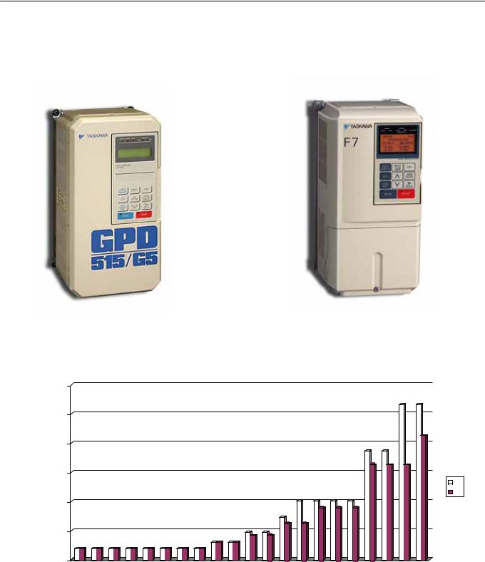
Physical Dimensions
Between 20 - 200 HP, the F7 is 18% smaller volume on average than the equivalent GPD515/G5. (See appendix 1)
Based on meeting NEC full load amp requirements, the F7 footprint can offer a space savings over the GPD515/G5.
|
|
|
|
|
|
|
F7 vs. G5 Footprint area |
|
|
|
|
|
|
|
|
|
|
|
|
||||||
600000 |
|
|
|
|
|
|
|
|
|
|
|
|
|
|
|
|
|
|
|
|
|
|
|
|
|
500000 |
|
|
|
|
|
|
|
|
|
|
|
|
|
|
|
|
|
|
|
|
|
|
|
|
|
400000 |
|
|
|
|
|
|
|
|
|
|
|
|
|
|
|
|
|
|
|
|
|
|
|
|
|
Area (mm2) 300000 |
|
|
|
|
|
|
|
|
|
|
|
|
|
|
|
|
|
|
|
|
|
|
|
|
|
|
|
|
|
|
|
|
|
|
|
|
|
|
|
|
|
|
|
|
|
|
|
|
|
|
G5 |
|
|
|
|
|
|
|
|
|
|
|
|
|
|
|
|
|
|
|
|
|
|
|
|
|
F7 |
200000 |
|
|
|
|
|
|
|
|
|
|
|
|
|
|
|
|
|
|
|
|
|
|
|
|
|
100000 |
|
|
|
|
|
|
|
|
|
|
|
|
|
|
|
|
|
|
|
|
|
|
|
|
|
0 |
|
|
|
|
|
|
|
|
|
|
|
|
|
|
|
|
|
|
|
|
|
|
|
|
|
.5 |
.8 |
.0 |
.5 |
.0 |
.0 |
.0 |
.5 |
.0 |
.0 |
.0 |
.0 |
|
.0 |
|
.0 |
|
.0 |
|
.0 |
|
.0 |
.0 |
.0 |
.0 |
.0 |
0 |
0 |
1 |
1 |
2 |
3 |
5 |
7 |
10 |
15 |
20 |
25 |
0 |
0 |
0 |
0 |
5 |
100 |
125 |
150 |
200 |
|||||
|
|
|
|
|
|
|
|
3 |
|
4 |
|
5 |
|
6 |
|
7 |
|
||||||||
NEC HP Rating
Note: 645.16 square mm to 1 square inch
__________________________
PL.F7.02.TransitionGuide 6/5/06
Page 12 of 40
Yaskawa Electric America, Inc
Loading...