


 Loading...
Product Transition Guide
GPD 515/G5 to G7
PL.G7.02.Transition Guide

Product Transition Guide
GPD515/G5 to G7
NOTICE
The information contained within this document is the proprietary property of Yaskawa Electric America, Inc., and may not be copied, reproduced or transmitted to other parties without the expressed written authorization of Yaskawa Electric America, Inc. No patent liability is assumed with respect to the use of the information contained herein. Moreover, because Yaskawa is constantly improving its high-quality products, the information contained in this document is subject to change without notice. Every precaution has been taken in the preparation of this document. Nevertheless, Yaskawa assumes no responsibility for errors or omissions. Neither is any liability assumed for damages resulting from the use of the information contained in this publication.
__________________________
PL.G7.02.TransitionGuide 4/21/04
Page 2 of 38
Yaskawa Electric America, Inc

Product Transition Guide
GPD515/G5 to G7
Contents
Feature Overview ....................................................................................................... |
5 |
G7 Benefits vs. G5 ..................................................................................................... |
5 |
Main Specification Differences G5 to G7................................................................... |
6 |
Physical Dimensions .................................................................................................. |
9 |
I/O Terminal Cross Reference G5 to G7.................................................................. |
11 |
Physical I/O Block Terminal Layout .......................................................................... |
14 |
Main Power Terminal Comparison ........................................................................... |
14 |
Available Network Communications ......................................................................... |
16 |
Appendix 1................................................................................................................ |
17 |
Amps, Carriers, Overload, Watt Loss and Dimensions ..................................... |
117 |
Output Amps, Carrier and Overload Comparison |
|
240V Ratings GPD515/G5 to G7................................................................ |
18 |
Output Amps, Carrier and Overload Comparison |
|
480V Ratings GPD515/G5 to G7................................................................ |
19 |
Mounting Hole Data ..................................................................................... |
20 |
Panel Cut-out Data (for external heatsink mounting) ................................... |
21 |
Watts Loss Data .......................................................................................... |
22 |
Appendix 2................................................................................................................ |
23 |
Parameter Differences........................................................................................ |
23 |
__________________________
PL.G7.02.TransitionGuide 4/21/04
Page 3 of 38
Yaskawa Electric America, Inc

Product Transition Guide GPD515/G5 to G7
Page Intentionally Left Blank
__________________________
PL.G7.02.TransitionGuide 4/21/04
Page 4 of 38
Yaskawa Electric America, Inc
Product Transition Guide
GPD515/G5 to G7
Feature Overview
This document details differences between the GPD515/G5 and G7 product to assist in product transition and new product introduction.
GPD515/G5 Drive
The GPD 515/G5 drive is a generalpurpose drive, intended for a broad range of applications in Industrial Automation. Accordingly, it is available with many choices of I/O, communications, and software. It is available in constant torque ratings, 3/4 to 500 horsepower. The G5 HHP is available to 1500 HP.
G7 Benefits vs. G5
Enhanced G7 Performance
•Auto-tuning 3-Methods (R1/Static/Dynamic)
•World’s first commercial 3-Level Inverter architecture
(480V)
•Static no load auto-tuning offers same torque accuracy performance as dynamic auto-tuning at base speed & below
•DC input compatible (all models) simplified connection to DC power, removal of internal DC bus choke not required.
•Open-loop torque control
•Improved closed-loop speed response: 60Hz vs. 30Hz
•Improved open-loop speed response: 10Hz vs. 5Hz
•Improved open-loop speed range: 200:1 vs. 100:1
•Higher output frequency resolution: 0.001% vs. 0.01%
•Improved torque response: 300Hz vs. 150Hz
•Improved open loop starting torque: 0.3Hz vs. 0.5Hz
•Improved input voltage specification: 240 vs. 230 and 480 vs. 460.
New Keypad/Digital Operator
•Enhanced digital operator with copy function
•Simplified parameter menu navigation
•New LCD contrast adjustment
•Standard RJ-45 CAT-5 cable connection
New Functions
•New PID sleep function
•More preset speed selections: 17 vs. 9
•New automatic derating based on ambient temperature setting
•New Bi-directional speed search with speed estimation mode
G7 Drive
The G7 AC drive is the ultimate performance solution with increased speed and torque response to provide servo-like performance from an induction motor. The 480V G7 drive has the world’s first commercial 3-Level Inverter architecture for total system protection. This patented 3-Level architecture can eliminate peripheral components typically required to solve installation problems. G7 drive performance makes it the ideal drive for high performance speed, torque, or position control
applications. The G7 is available in constant torque/heavy duty ratings 0.5 to 500HP. The G7 is not intended for the simple, routine AC drive application, it is for the challenges.
(Refer to Yaskawa document “TR.G7.01 Technology Review G7 Drive” for more details on new G7 Technology.)
New Functions (continued)
•Six additional monitor parameters
•Improved Energy Savingsmanual/automatic modes
•High Slip Braking
•New cooling fan on/off control and elapsed time and cassette replacement design
•New 12-pulse diode bridge 18.5-300kW
•Built-in DC-link choke 18.5-300kW
Improved Input/Output Functions
•Analog outputs with new 4-20mA selection and 10 bit resolution.
•More digital inputs: 12 vs. 8
•Inputs now support sinking or sourcing (PNP/NPN)
•Inputs now support internal or external power supply
•More digital outputs 6 vs. 4
•More versatile analog outputs
•New pulse I/O (32kHz)
•New quick disconnect terminal I/O block
•New motor temperature analog input
•New motor overheat alarm outputs
•Additional under-torque and over-torque selection points
•Built-in RS485 Modbus RTU communication with self test mode
__________________________
PL.G7.02.TransitionGuide 4/21/04
Page 5 of 38
Yaskawa Electric America, Inc
Product Transition Guide
GPD515/G5 to G7
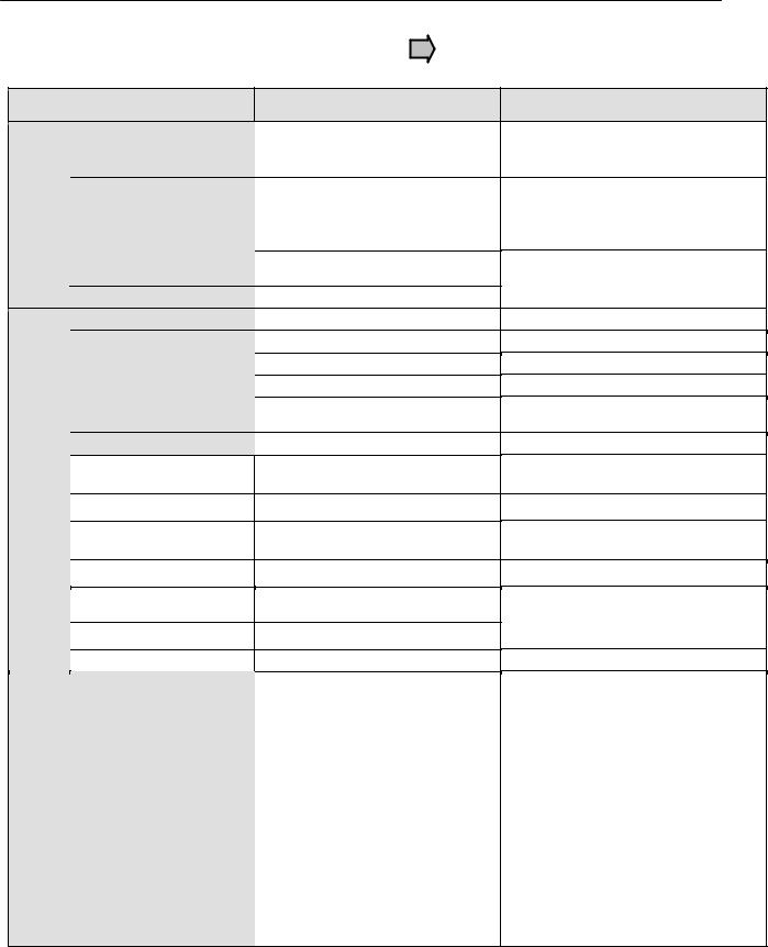
Main Specification Differences G5 to G7
|
Specification |
|
Control mode |
Ratings |
Inverter capacity range |
|
|
|
Main power circuit |
|
configuration |
|
Rated output current |
|
ASR scan time |
|
CASE scan time |
|
I/O Sequence Scan Time |
|
Microprocessor |
|
Output current limit |
|
protection |
Output frequency resolution
|
Speed control accuracy |
|
|
|
|
|
Speed control range |
|
|
|
|
|
Speed response |
|
Features |
|
|
Starting torque |
|
|
|
|
|
|
|
|
|
Motor surge protection |
|
Performance |
(480V) |
|
|
|
|
Open loop torque control |
|
|
|
|
|
|
|
|
|
Torque reference scan time |
|
|
|
|
G5 Specification
V/f, V/f w/ PG,
Open-loop vector,
Closed-loop flux vector
460V 0.4kW to 300kW (0.5 to 400HP)
230V 0.4kW to 110kW (0.5 to 150HP)
575V 1.5kW to 160kW (2 to 200HP) Modular: 300 to 1800HP (VT)
2-Level
Example: 240V class, 3.7kW, 17.5A
2msec
5msec
5msec
First generation
Hardware
0.01Hz
Open-loop vector: ±0.2%, Closed-loop flux vector: ±0.02%
Open-loop vector: 100:1
Open-loop vector: 5Hz Closed-loop flux vector: 30Hz
Open-loop vector: 150% at 1Hz
No
No
2msec
V/f, V/f w/ PG,
Open-loop vector, Closed-loop flux vector, Open-loop vector 2
480V 0.4kW to 300kW (0.5 to 400HP)
240V 0.4kW to 110kW (0.5 to 150HP)
3-Level
Example: 240V class, 3.7kW, 18A 1.25msec (except Open-loop vector 2) 2.5msec (except Open-loop vector 2) 2.5msec (except Open-loop vector 2) Second generation
Hardware, Software
0.001Hz
Open-loop vector 2: ±0.1%, Closed-loop flux vector: ±0.01%
Open-loop vector 2: 200:1
Open-loop vector 2: 10Hz Closed-loop flux vector: 60Hz
Open-loop vector 2: 150% at 0.3Hz
Yes (3-Level)
Yes (Open-loop vector 2) 1.25msec (except Open-loop vector 2)
|
150Hz |
300Hz |
|
Torque response |
|||
(Closed-loop flux vector) |
(Closed-loop flux vector) |
||
|
__________________________
PL.G7.02.TransitionGuide 4/21/04
Page 6 of 38
Yaskawa Electric America, Inc

Product Transition Guide
GPD515/G5 to G7
Specification
|
I/O |
|
Quick disconnect I/O |
|
|
|
terminals |
|
|
|
|
|
|
|
|
|
|
||
Analog Inputs |
Programmable functions |
|
||
|
|
|
|
|
|
|
|
|
|
Analog Outputs |
Quantity |
|
Type |
||
|
||
|
Programmable functions |
|
Digital Inputs |
Quantity |
|
Type |
||
|
||
|
Programmable functions |
|
|
Quantity |
|
Digital Outputs |
Type |
|
|
||
Pulse Input |
Quantity |
|
Signal level |
||
|
||
|
Programmable functions |
|
Pulse Output |
Quantity |
|
Signal level |
||
|
||
Stopping |
Programmable functions |
|
Flux/High slip braking |
||
|
Braking DB transistor |
|
Cooling Fan |
Modular replacement |
|
Cumulative fan operation |
||
|
On/Off control |
|
Design Features |
time |
|
Auto-tuning |
||
|
G5 Specification
No
39
0-±10VDC x 2
-10-10VDC x 2 (8 bit plus sign)
27
8
24VDC, NPN
Photo coupler isolation, 8mA
45
4
•Qty 1: Programmable: Form A, 250VAC, 1A, 30VDC, 1A
•Qty 1: Dedicated Fault, Form C, 250VAC, 1A, 30VDC, 1A
•Qty 2: Programmable, photocoupler (open collector output), 48V, 50mA, common emitter connection
0
~
~
0 standard (1 with option)
~
~
Built-in to G5M27P5 (10HP) Built-in to G5M4015 (25HP)
No
No
No
No
Rotational
Yes
45
0-±10VDC/4-20mA x 2
-10-10VDC or 4-20mA x 2 (8 bit plus sign)
30
12
24VDC, sinking or sourcing (NPN/PNP) Photo coupler isolation, 8mA
Internal or external power supply 51 6
•Qty 3: Programmable: Form A, 250VAC, 1A, 30VDC, 1A
•Qty 1: Dedicated Fault, Form C, 250VAC, 1A, 30VDC, 1A
•Qty 2: Programmable, photo-coupler (open collector output), 48V, 50mA, separate emitter connection
1
0-32kHz, low level: 0.0-0.8VDC high level: 3.5-13.2VDC, duty cycle: 30-70%, 3kohm
4
1
0-32kHz, 9.0VDC, 2.2kohm
6
Built-in to G7U2015 (20HP) Built-in to G7U4015 (25HP)
Yes
Yes
Yes
Yes
Rotational
Stationary
Stationary (primary resistance only)
__________________________
PL.G7.02.TransitionGuide 4/21/04
Page 7 of 38
Yaskawa Electric America, Inc

Product Transition Guide |
|
|
||
GPD515/G5 to G7 |
|
|
||
|
Specification |
G5 Specification |
|
|
|
Multi-step speed operation |
9-step speeds |
17-step speeds |
|
|
PID sleep mode |
No |
Yes |
|
|
User customized |
No |
Yes (DriveWorks EZ) |
|
|
programming |
|||
|
|
|
||
|
Speed search |
Current Detection |
Current Detection or Speed Estimation |
|
|
Uni-Directional |
Bi-directional for Speed Estimation |
||
|
|
|||
Design Features |
Split front cover |
No |
Yes |
|
Run permissive |
No |
Yes |
||
|
Timer Function |
On/Off delay (0.0-25.5sec) |
On/Off delay (0.0-300.0sec) |
|
|
Motor temperature input |
No |
Yes |
|
|
Undertorque detection |
No |
Yes |
|
Harmonics |
12-phase rectification input |
No |
240V, G7U2018-G7U2110 |
|
480V, G7U4018-G7U4300 |
||||
DC choke built-in |
460V, G5M4018-G5M4160 |
|||
|
|
|
480V, G7U4018-G7U4300 |
|
|
|
230V, G5M2018-G5M2075 |
240V, G7U2018-G7U2110 |
|
|
Constant access level |
3-level selectable |
2-level selectable |
|
Keypad/Operator |
selection |
(Quick-Start, Basic, Advanced) |
(Quick-Program, Advanced) |
|
Copy function |
No (optional keypad) |
Yes |
||
|
||||
|
Display |
2 Line x 16 Character LCD |
5 Line x 16 Character LCD |
|
|
(Contrast Adjustable) |
|||
|
|
|
||
|
Monitoring |
1 monitor |
3 sequential monitors at same time |
|
|
Verify function |
Yes |
Modified constants can be displayed. |
|
|
Viewable monitors |
35 |
40 |
|
Network Communications |
Built-in |
Modbus RTU (RS-232, 9.6kbps) |
Modbus RTU (RS-232/422/485, 19.2kbps) |
|
|
Profibus-DP, Modbus Plus |
Profibus-DP, Modbus Plus, LonWorks |
||
|
|
Modbus RTU (RS-422/485), Ethernet |
Ethernet (Modbus/ TCP/IP), DeviceNet, |
|
|
Option Card |
(Modbus/ TCP/IP), DeviceNet, |
||
|
|
|||
|
|
3-phase, 200-230VAC |
3-phase, 200-240VAC |
|
Conditions |
Input specifications |
3-phase, 380-460VAC, |
3-phase, 380-480VAC |
|
|
Tolerance: +10 to -15% |
Tolerance: +10 to -15% |
||
|
|
|||
|
|
|
240V: 60HP (2037) and Below, 480V: 75HP |
|
|
|
|
(4045) and Below |
|
Service |
|
|
1.0G (9.8m/s^2) 10 to 20Hz |
|
|
|
(4055) and Above |
||
|
Vibration/Shock |
~ |
0.6G (5.9m/s^2) 20 to 55Hz |
|
|
240V: 60HP (2045) and Above, 480V: 100HP |
|||
|
|
|
||
|
|
|
1.0G (9.8m/s^2) 10 to 20Hz |
|
Storage Temp |
|
|
0.2G (2.0m/s^2) 20 to 55Hz |
|
ºC |
-10ºC ~ +60ºC |
-20ºC ~ +60ºC |
||
|
||||
__________________________
PL.G7.02.TransitionGuide 4/21/04
Page 8 of 38
Yaskawa Electric America, Inc

Product Transition Guide
Terminal Comparison
Physical Dimensions
Between 20 - 200 HP, the G7 is 18% smaller volume on average than the equivalent GPD515/G5.
(See appendix 1) Based on meeting NEC full load amp requirements, the G7 footprint can offer a space savings over the GPD515/G5.
G7– 18% less volume compared to GPD515/G5
__________________________
PL.G7.02.TransitionGuide 4/21/04
Page 9 of 38
Yaskawa Electric America, Inc
Product Transition Guide
GPD515/G5 to G7
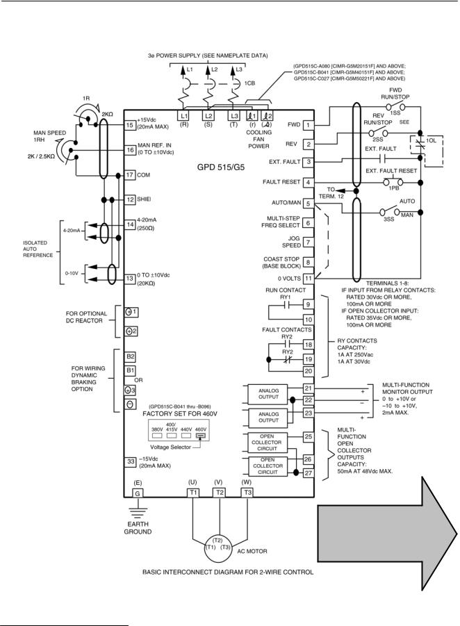
GPD515/G5 Terminal Description
GPD515/G5
Compare to G7 terminals, see next page.
PL.G7.02.TransitionGuide 4/21/04
Page 10 of 38
Yaskawa Electric America, Inc

Product Transition Guide
GPD515/G5 to G7
G7 Terminal Description
G7
__________________________
PL.G7.02.TransitionGuide 4/21/04
Page 11 of 38
Yaskawa Electric America, Inc

Product Transition Guide
GPD515/G5 to G7
I/O Terminal Cross Reference G5 to G7
|
|
|
GPD515/G5 Terminal |
|
G7 Terminal |
|||
|
|
|
|
|||||
Type |
GPD515/G5 |
Default Function |
G7 |
Default Function |
G7 Description |
|||
Terminal |
Terminal |
|||||||
|
|
|
|
|
|
|||
|
|
|
|
|
|
|
|
|
|
|
|
1 |
Forward run/stop |
S1 |
Forward run/stop command |
– |
|
|
|
|
||||||
|
|
|
Signal level: (Photo-coupler |
|||||
|
|
|
|
insulated input: +24VDC, 8mA) |
|
|
|
|
|
|
|
2 |
Reverse run/stop |
S2 |
Reverse run/stop command |
– |
|
|
|
|
3 |
External fault input |
S3 |
External fault input |
|
|
|
|
|
|
|
|
|
|
|
|
Signals |
|
4 |
Fault reset input |
S4 |
Fault reset |
|
|
|
|
|
Multi-step speed ref.1 |
|
(Master/auxiliary switch) |
|
||
|
|
|
5 |
Master/Aux. change |
S5 |
Multi-step speed reference 1 |
Multi-function digital inputs |
|
|
Input |
|
|
|
||||
|
|
6 |
Multi-step speed ref.2 |
S6 |
Multi-step speed reference 2 |
Functions set by: |
||
|
|
7 |
Jog reference |
S7 |
Jog frequency reference |
H1-01 to H1-10. |
||
|
Digital |
|
|
|
|
|
+24VDC, 8mA |
|
|
|
8 |
External baseblock |
S8 |
External baseblock N.O. |
|||
|
|
Photo coupler isolation |
||||||
|
|
|
– |
S9 |
Multi-step speed reference 3 |
|||
|
|
|
|
|||||
|
|
|
|
– |
S10 |
Multi-step speed reference 4 |
|
|
|
|
|
|
– |
S11 |
Accel/Decel time select |
|
|
|
|
|
|
– |
S12 |
Emergency Stop N.O. |
|
|
|
|
|
11 |
Sequence control input common |
SN |
Digital input common |
Factory connected for internal |
|
|
|
|
|
|
|
|
supply, sinking mode. |
|
|
|
|
|
– |
SC |
Factory connected to SP |
||
|
|
|
|
Refer to G7 User Manual for |
||||
|
|
|
|
– |
SP |
Factory connected to SC |
||
|
|
|
|
other methods. |
||||
|
|
|
|
|
|
|
|
|
|
|
|
15 |
+15VDC Power supply |
+V |
+15VDC power supply |
+15VDC |
|
|
|
|
(20mA maximum) |
(20mA maximum) |
||||
|
|
|
|
|
|
|||
|
|
|
|
|
|
|
|
|
|
|
|
33 |
-15VDC Power supply |
-V |
-15VDC power supply |
-15VDC |
|
|
Signals |
|
(20mA maximum) |
(20mA maximum) |
||||
|
|
|
|
|
||||
|
|
|
|
|
|
|
||
|
13 |
Master frequency ref. (voltage) |
A1 |
Master frequency reference |
0 to +10VDC=100% |
|||
|
|
|
||||||
|
|
|
-10 to +10VDC (20kohm) |
0 to +/-10VDC=100% (H3-01) |
||||
|
Input |
|
|
0 to +10VDC (20kohm) |
|
|
(20kohm) |
|
|
|
14 |
Master frequency ref. (current) |
A2 |
Add to terminal A1 |
4 to 20mA=100% (250ohm) |
||
|
|
|
||||||
|
Analog |
|
4 to 20mA (250ohm) |
0 to +10VDC=100% (20kohm) |
||||
|
|
|
|
|
|
Function set by H3-09. |
||
|
|
16 |
Multi-function analog input |
A3 |
Auxiliary frequency |
0 to +10Vdc=100%/(20kohm) |
||
|
|
|
-10 to +10VDC (20kohm), |
reference 1 |
0 to +/-10Vdc=100% |
|||
|
|
|
|
0 to +10VDC (20kohm) |
|
Function set by H3-05 |
||
|
|
|
|
|
|
|||
|
|
|
17 |
Common for control circuit 0V |
AC |
Analog common |
– |
|
|
|
|
12 |
Connection to shield sheath of |
E(G) |
Shield wire, optional ground |
– |
|
|
|
|
signal lead |
line connection point |
||||
|
|
|
|
|
|
|||
|
|
|
|
|
|
|
|
|
PL.G7.02.TransitionGuide 4/21/04
Page 12 of 38
Yaskawa Electric America, Inc
Loading...