


G7
Table of contents
 Loading...
G7 Drive
Technical Manual
Models: CIMR-G7U Document Number: TM.G7.01

Warnings and Cautions
WARNING
WARNING
WARNING
This Section provides warnings and cautions pertinent to this product, that if not
heeded, may result in personal injury, fatality, or equipment damage. Yaskawa is
not responsible for consequences of ignoring these instructions.
YASKAWA manufactures component parts that can be used in a wide variety of industrial applications. The selection and
application of YASKAWA products remain the responsibility of the equipment designer or end user. YASKAWA accepts no
responsibility for the way its products are incorporated into the final system design. Under no circumstances should any
YASKAWA product be incorporated into any product or design as the exclusive or sole safety control. Without exception, all
controls should be designed to detect faults dynamically and fail safely under all circumstances. All products designed to
incorporate a component part manufactured by YASKAWA must be supplied to the end user with appropriate warnings and
instructions as to that part’s safe use and operation. Any warnings provided by YASKAWA must be promptly provided to the
end user. YASKAWA offers an express warranty only as to the quality of its products in conforming to standards and
specifications published in the YASKAWA manual. NO OTHER WARRANTY, EXPRESS OR IMPLIED, IS OFFERED.
YASKAWA assumes no liability for any personal injury, property damage, losses, or claims arising from misapplication of its
products.
• Read and understand this manual before installing, operating, or servicing this Drive. All warnings, cautions, and
instructions must be followed. All activity must be performed by qualified personnel. The Drive must be installed according
to this manual and local codes.
• Do not connect or disconnect wiring while the power is on. Do not remove covers or touch circuit boards while the power is
on. Do not remove or insert the digital operator while power is on.
• Before servicing, disconnect all power to the equipment. The internal capacitor remains charged even after the power supply
is turned off. The charge indicator LED will extinguish when the DC bus voltage is below 50Vdc. To prevent electric shock,
wait at least five minutes after all indicators are OFF and measure DC bus voltage level to confirm safe level.
• Do not perform a withstand voltage test on any part of the unit. This equipment uses sensitive devices and may be damaged
by high voltage.
• The Drive is suitable for circuits capable of delivering not more than 100,000 RMS symmetrical Amperes, 240Vac
maximum (200-240V Class) and 480Vac maximum (380-480V Class). Install adequate branch circuit short circuit protection per applicable codes. Failure to do so may result in equipment damage and/or personal injury. Refer to Appendix E for
further details.
• Do not connect unapproved LC or RC interference suppression filters, capacitors, or overvoltage protection devices to the
output of the Drive. These devices may generate peak currents that exceed Drive specifications.
i

• To avoid unnecessary fault displays caused by contactors or output switches placed between Drive and motor, auxil-
iary contacts must be properly integrated into the control logic circuit.
• YASKAWA is not responsible for any modification of the product made by the user; doing so will void the warranty.
This product must not be modified.
• Verify that the rated voltage of the Drive matches the voltage of the incoming power supply before applying power.
• To meet CE directives, proper line filters and proper installation are required.
• Some drawings in this manual may be shown with protective covers or shields removed, to describe details. These
must be replaced before operation.
• Observe electrostatic discharge procedures when handling circuit boards to prevent ESD damage.
• The equipment may start unexpectedly upon application of power. Clear all personnel from the Drive, motor, and
machine area before applying power. Secure covers, couplings, shaft keys, and machine loads before energizing the
Drive.
• Please do not connect or operate any equipment with visible damage or missing parts. The operating company is
responsible for any injuries or equipment damage resulting from failure to heed the warnings in this manual.
Intended Use
Drives are intended for installation in electrical systems or machinery.
The Drives are designed and manufactured in accordance with applicable UL and cUL standards, and CE directives.
For use in the European Union, the installation in machinery and systems must conform to the following product standards of the Low Voltage Directive:
EN 50178: 1997-10, Electronic Equipment for Use in Power Installations
EN 60201-1: 1997-12 Machine Safety and Equipping with Electrical Devices
Part 1: General Requirements (IEC 60204-1:1997)
EN 61010: 1997-11 Safety Requirements for Information Technology Equipment
(IEC 950:1991 + A1:1992 + A2:1993 + A3:1995 + A4:1996, modified)
The F7 series Drives comply with the provisions of the Low Voltage Directive 73/23/EEC as amended by 93/68/EEC.
These Drives conform to the following standard: EN 50178: 1997-10.
Your supplier or Yaskawa representative must be contacted when using leakage current circuit breaker in conjunction
with frequency drives.
In certain systems it may be necessary to use additional monitoring and safety devices in compliance with the relevant
safety and accident prevention regulations. The frequency drive hardware must not be modified.
ii
Safety Precautions
CAUTION
Installation
• Always hold the case when carrying the Drive.
If the Drive is held by the front cover, the main body of the Drive may fall, possibly resulting in injury.
• Attach the Drive to a metal or other noncombustible material.
Fire can result if the Drive is attached to a combustible material.
• Install a cooling fan or other cooling device when installing more than one Drive in the same enclosure so that the temperature of the air entering the Drives is below 45°C.
Overheating can result in fires or other accidents.
iii
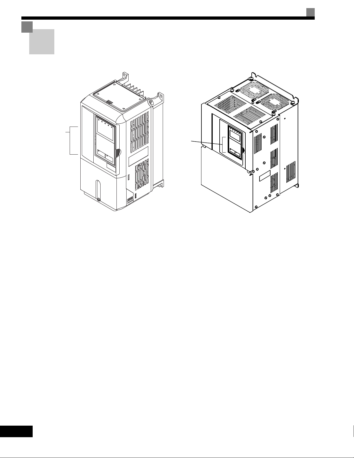
Warning Information and Position
Illustration shows the CIMR-G7U20P4
Warning
information
position
Illustration shows the CIMR-G7U2018
Warning
information
position
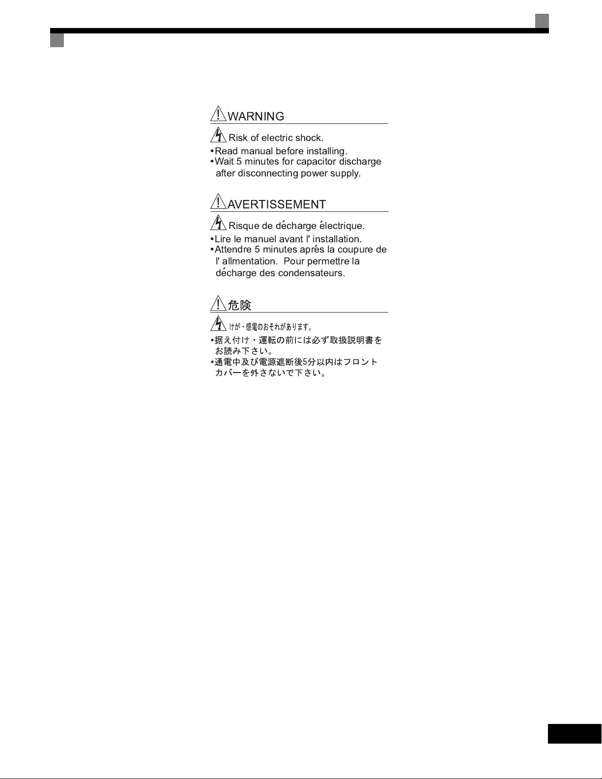
There is warning information on the Drive in the position shown in the following illustration.
Always heed the warnings.
Warning Information
iv
!"##!$!"
% %
& ' (
( )
(
(
(
(
v

Registered Trademarks
The following registered trademarks are used in this manual.
• DeviceNet is a registered trademark of the ODVA (Open DeviceNet Vendors Association, Inc.).
• ControlNet is a registered trademark of ControlNet International, Ltd.
• LONworks is a registered trademark of the Echelon.
• MODBUS is a registered trademark of the MODBUS.org.
vi

Contents
1 Handling Drives ...................................................................... 1-1
Varispeed G7 Introduction ............................................................................1-2
Varispeed G7 Models .....................................................................................................1-2
Confirmations upon Delivery ........................................................................1-3
Checks............................................................................................................................1-3
Nameplate Information ...................................................................................................1-3
Component Names .........................................................................................................1-5
Exterior and Mounting Dimensions...............................................................1-7
Open Chassis Drives (IP00) ...........................................................................................1-7
NEMA Type 1 Drives (IP 20)...........................................................................................1-8
Checking and Controlling the Installation Site ............................................1-10
Installation Site .............................................................................................................1-10
Controlling the Ambient Temperature ...........................................................................1-10
Protecting the Drive from Foreign Matter...................................................................... 1-10
Installation Orientation and Space ..............................................................1-11
Removing and Attaching the Terminal Cover .............................................1-12
Removing the Terminal Cover ......................................................................................1-12
Attaching the Terminal Cover........................................................................................1-13
Removing/Attaching the Digital Operator and Front Cover ........................1-14
Models CIMR-G7U20P4 thru 2015 and 40P4 thru 4015 ..............................................1-14
Models CIMR-G7U2018 thru 2110 and 4018 thru 4300 ............................................... 1-17
2 Wiring....................................................................................... 2-1
Connection Diagram.....................................................................................2-2
Terminal Block Configuration ........................................................................2-4
Wiring Main Circuit Terminals .......................................................................2-5
Applicable Wire Sizes and Closed-loop Connectors ......................................................2-5
Main Circuit Terminal Functions ...................................................................................2-13
Main Circuit Configurations...........................................................................................2-14
Standard Connection Diagrams....................................................................................2-15
Wiring the Main Circuits................................................................................................2-16
Wiring Control Circuit Terminals .................................................................2-22
Wire Sizes and Closed-loop Connectors ......................................................................2-22
Control Circuit Terminal Functions ............................................................................... 2-23
Control Circuit Terminal Connections ........................................................................... 2-29
vii

Control Circuit Wiring Precautions ............................................................................... 2-30
Control Circuit Wire Sizes ............................................................................................ 2-30
Wire Checks ................................................................................................................. 2-30
Installing and Wiring Option Cards............................................................. 2-31
Option Card Models and Specifications ....................................................................... 2-31
Installation ....................................................................................................................2-32
PG Speed Control Card Terminals and Specifications ................................................. 2-33
Wiring ........................................................................................................................... 2-36
Wiring Terminal Blocks................................................................................................. 2-40
Selecting the Number of PG (Encoder) Pulses ............................................................ 2-41
3 Digital Operator and Modes....................................................3-1
Digital Operator ............................................................................................ 3-2
Digital Operator Display ................................................................................................. 3-2
Digital Operator Keys ..................................................................................................... 3-3
Modes .......................................................................................................... 3-5
Drive Modes ................................................................................................................... 3-5
Switching Modes ............................................................................................................ 3-6
Drive Mode ..................................................................................................................... 3-7
Quick Programming Mode.............................................................................................. 3-9
Advanced Programming Mode ..................................................................................... 3-10
Verify Mode .................................................................................................................. 3-13
Autotuning Mode .......................................................................................................... 3-14
4 Trial Operation .........................................................................4-1
Trial Operation Procedure............................................................................ 4-2
Trial Operation Procedures .......................................................................... 4-3
Setting the Power Supply Voltage Jumper (380-480V Class Drives of 4055 or Higher) 4-3
Power ON ....................................................................................................................... 4-3
Checking the Display Status .......................................................................................... 4-4
Basic Settings................................................................................................................. 4-5
Settings for the Control Methods .................................................................................... 4-7
Autotuning ......................................................................................................................4-9
Application Settings ...................................................................................................... 4-14
No-load Operation ........................................................................................................ 4-14
Loaded Operation......................................................................................................... 4-15
Check and Recording User Parameters....................................................................... 4-16
Adjustment Suggestions ............................................................................ 4-17
viii

5 User Parameters ..................................................................... 5-1
User Parameter Descriptions .......................................................................5-2
Description of User Parameter Tables ............................................................................ 5-2
Digital Operation Display Functions and Levels ...........................................5-3
User Parameters Settable in Quick Programming Mode................................................ 5-4
User Parameter Tables...............................................................................5-10
A: Setup Settings.......................................................................................................... 5-10
Application Parameters: b.............................................................................................5-12
Autotuning Parameters: C ............................................................................................ 5-22
Reference Parameters: d..............................................................................................5-28
Motor Setup Parameters: E ..........................................................................................5-34
Option Parameters: F ...................................................................................................5-41
Terminal Function Parameters: H.................................................................................5-50
Protection Function Parameters: L ...............................................................................5-61
N: Special Adjustments.................................................................................................5-74
Digital Operator Parameters: o .....................................................................................5-80
T: Motor Autotuning ......................................................................................................5-84
U: Monitor Parameters..................................................................................................5-86
Factory Settings that Change with the Control Method (A1-02) ...................................5-96
Factory Settings that Change with the Drive Capacity (o2-04)...................................5-102
6 Parameter Settings by Function............................................ 6-1
Frequency Reference ...................................................................................6-2
Selecting the Frequency Reference Source ...................................................................6-2
Using Multi-Step Speed Operation .................................................................................6-5
Run Command .............................................................................................6-7
Selecting the Run Command Source .............................................................................6-7
Stopping Methods.........................................................................................6-9
Selecting the Stopping Method when a Stop Command is Sent..................................... 6-9
Using the DC Injection Brake........................................................................................6-13
Using an Emergency Stop ............................................................................................6-14
Acceleration and Deceleration Characteristics...........................................6-15
Setting Acceleration and Deceleration Times...............................................................6-15
Accelerating and Decelerating Heavy Loads (Dwell Function)..................................... 6-19
Preventing the Motor from Stalling During Acceleration (Stall Prevention During
Acceleration Function)..................................................................................................6-20
Preventing Overvoltage During Deceleration (Stall Prevention During Deceleration
Function).......................................................................................................................6-22
Adjusting Frequency References ...............................................................6-24
Adjusting Analog Frequency References .....................................................................6-24
Operation Avoiding Resonance (Jump Frequency Function) ....................................... 6-27
Adjusting Frequency Reference Using Pulse Train Inputs ...........................................6-29
ix

Speed Limit (Frequency Reference Limit Function) ...................................6-30
Limiting Maximum Output Frequency........................................................................... 6-30
Limiting Minimum Frequency ....................................................................................... 6-31
Improved Operating Efficiency ................................................................... 6-32
Reducing Motor Speed Fluctuation (Slip Compensation Function).............................. 6-32
Compensating for Insufficient Torque at Startup and Low-speed Operation
(Torque Compensation) ................................................................................................ 6-35
Hunting-prevention Function ........................................................................................ 6-37
Stabilizing Speed (Speed Feedback Detection Function) ............................................ 6-38
Machine Protection ....................................................................................6-39
Reducing Noise and Leakage Current ......................................................................... 6-39
Limiting Motor Torque (Torque Limit Function) ............................................................ 6-42
Preventing Motor Stalling During Operation ................................................................. 6-44
Changing Stall Prevention Level during Operation Using an Analog Input .................. 6-45
Detecting Motor Torque................................................................................................ 6-45
Changing Overtorque and Undertorque Detection Levels Using an Analog Input ....... 6-50
Motor Overload Protection ........................................................................................... 6-51
Setting Motor Protection Operation Time ..................................................................... 6-53
Motor Overheating Protection Using PTC Thermistor Inputs ....................................... 6-54
Limiting Motor Rotation Direction ................................................................................. 6-56
Continuing Operation ................................................................................. 6-57
Restarting Automatically After Power Is Restored........................................................ 6-57
Speed Search............................................................................................................... 6-59
Continuing Operation at Constant Speed When Frequency Reference Is Lost ........... 6-65
Restarting Operation After Transient Error (Auto Restart Function) ............................ 6-66
Drive Protection.......................................................................................... 6-67
Performing Overheating Protection on Mounted Braking Resistors ............................. 6-67
Reducing Drive Overheating Pre-Alarm Warning Levels ............................................. 6-68
Input Terminal Functions ............................................................................6-69
Temporarily Switching Operation between Digital Operator and Control Circuit
Terminals ...................................................................................................................... 6-69
Blocking Drive Outputs (Baseblock Commands) ......................................................... 6-70
Stopping Acceleration and Deceleration (Acceleration/Deceleration Ramp Hold)....... 6-71
Raising and Lowering Frequency References Using Contact Signals (UP/DOWN) .... 6-72
Accelerating and Decelerating Constant Frequencies in the Analog References
(+/- Speed) ................................................................................................................... 6-75
Hold Analog Frequency Using User-set Timing ........................................................... 6-76
Switching Operations between a Communications Option Card and Control Circuit
Terminals ...................................................................................................................... 6-76
Jog Frequency Operation without Forward and Reverse Commands (FJOG/RJOG) . 6-77
Stopping the Drive by Notifying Programming Device Errors to the Drive
(External Fault Function) .............................................................................................. 6-78
x

Monitor Parameterss ..................................................................................6-79
Using the Analog Monitor Parameters..........................................................................6-79
Using Pulse Train Monitor Contents .............................................................................6-82
Individual Functions....................................................................................6-84
Using MODBUS Communications ................................................................................6-84
Using the Timer Function..............................................................................................6-97
Using PID Control .........................................................................................................6-98
Energy-saving ............................................................................................................. 6-107
Setting Motor Parameters...........................................................................................6-108
Setting the V/f Pattern.................................................................................................6-111
Torque Control ............................................................................................................ 6-120
Speed Control (ASR) Structure...................................................................................6-128
Droop Control Function...............................................................................................6-134
Zero-servo Function....................................................................................................6-135
Digital Operator Functions........................................................................6-139
Setting Digital Operator Functions..............................................................................6-139
Copying Parameters ...................................................................................................6-143
Prohibiting Writing Parameters from the Digital Operator........................................... 6-148
Setting a Password .....................................................................................................6-149
Displaying User-set Parameters Only.........................................................................6-149
Options .....................................................................................................6-151
Performing Speed Control with PG.............................................................................6-151
Using Digital Output Cards .........................................................................................6-156
Using an Analog Reference Card ...............................................................................6-159
Using a Digital Reference Card ..................................................................................6-159
7 Troubleshooting ..................................................................... 7-1
Protective and Diagnostic Functions ............................................................7-2
Fault Detection................................................................................................................7-2
Alarm Detection .............................................................................................................. 7-9
Operation Errors ...........................................................................................................7-13
Errors During Autotuning .............................................................................................7-15
Errors when Using the Digital Operator Copy Function................................................7-17
Troubleshooting..........................................................................................7-18
If Parameters Cannot Be Set........................................................................................7-18
If the Motor Does Not Operate......................................................................................7-19
If the Direction of the Motor Rotation is Reversed ........................................................7-21
If the Motor Does Not Put Out Torque or If Acceleration is Slow ..................................7-21
If the Motor Operates Higher Than the Reference .......................................................7-22
If the Slip Compensation Function Has Low Speed Precision......................................7-22
If There is Low Speed Control Accuracy at High-speed Rotation in Open-loop Vector
Control Mode ................................................................................................................7-22
xi

If Motor Deceleration is Slow........................................................................................ 7-23
If the Motor Overheats.................................................................................................. 7-24
If There is Noise When the Drive is Started or From an AM Radio.............................. 7-24
If the Ground Fault Interrupter Operates When the Drive is Run ................................. 7-25
If There is Mechanical Oscillation................................................................................. 7-25
If the Motor Rotates Even When Drive Output is Stopped ........................................... 7-26
If 0 V is Detected When the Fan is Started, or Fan Stalls............................................. 7-26
If Output Frequency Does Not Rise to Frequency Reference ...................................... 7-27
8 Maintenance and Inspection ..................................................8-1
Maintenance and Inspection ........................................................................ 8-2
Outline of Maintenance .................................................................................................. 8-2
Daily Inspection .............................................................................................................. 8-2
Periodic Inspection ......................................................................................................... 8-2
Periodic Maintenance of Parts ....................................................................................... 8-3
Cooling Fan Replacement Outline ................................................................................. 8-4
Removing and Mounting the Control Circuit Terminal Card........................................... 8-6
9 Specifications ..........................................................................9-1
Standard Drive Specifications ...................................................................... 9-2
Specifications by Model.................................................................................................. 9-2
Common Specifications.................................................................................................. 9-4
Specifications of Options and Peripheral Devices........................................ 9-5
10 Appendix ................................................................................10-1
Varispeed G7 Control Modes .....................................................................10-2
Control Modes and Features........................................................................................ 10-2
Control Modes and Applications................................................................................... 10-6
Drive Application Precautions .................................................................... 10-7
Selection....................................................................................................................... 10-7
Installation .................................................................................................................... 10-8
Settings ........................................................................................................................ 10-8
Handling .......................................................................................................................10-9
Motor Application Precautions .................................................................10-10
Using the Drive for an Existing Standard Motor ......................................................... 10-10
Using the Drive for Special Motors ............................................................................. 10-11
Power Transmission Mechanism (Speed Reducers, Belts, and Chains) ................... 10-11
xii
Conformance to CE Markings .................................................................. 10-12
CE Markings............................................................................................................... 10-12
Requirements for Conformance to CE Markings ........................................................ 10-12
User Parameters ......................................................................................10-19

Handling Drives
This chapter describes the checks required upon receiving or installing an Drive.
Varispeed G7 Introduction ........................................... 1-2
Confirmations upon Delivery........................................1-3
Exterior and Mounting Dimensions..............................1-7
Checking and Controlling the Installation Site ........... 1-10
Installation Orientation and Space ............................. 1-11
Removing and Attaching the Terminal Cover ............1-12
Removing/Attaching the Digital Operator
and Front Cover .........................................................1-14
Varispeed G7 Introduction
Varispeed G7 Models
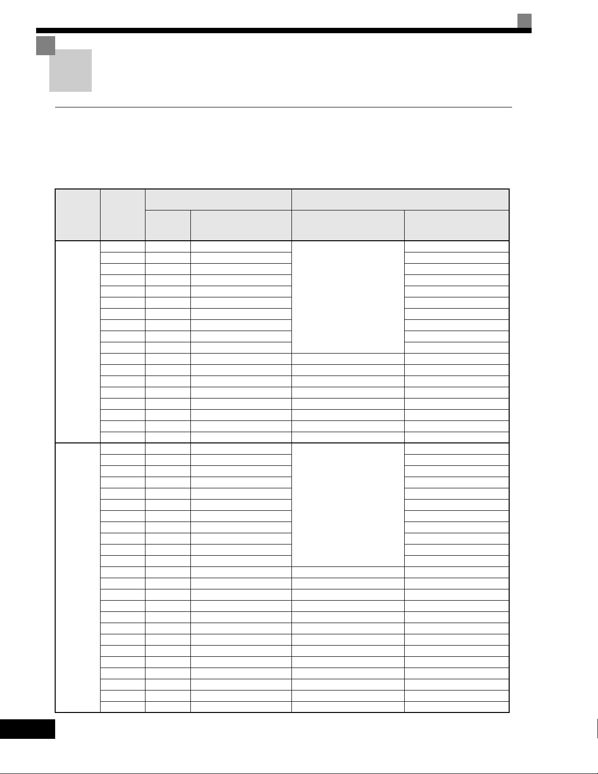
The Varispeed-G7 Series of Drives included two Drives in two voltage classes: 200-240V and 380-480V. Maximum motor
capacities vary from 20P4 to 2110 and 40P4 to 4300 (42 models).
Voltage
Class
200-240V
class
380-480V
class
Table 1.1 Varispeed
Maximum
Motor
Capacity
kW
0.4 1.2 CIMR-G7U20P4
0.75 2.3 CIMR-G7U20P7 20P71
1.5 3.0 CIMR-G7U21P5 21P51
2.2 4.6 CIMR-G7U22P2 22P21
3.7 6.9 CIMR-G7U23P7 23P71
5.5 10 CIMR-G7U25P5 25P51
7.5 13 CIMR-G7U27P5 27P51
11 19 CIMR-G7U2011 2011
15 25 CIMR-G7U2015 20151
18.5 30 CIMR-G7U2018 20181
22 37 CIMR-G7U2022 - 20220
30 50 CIMR-G7U2030 20300 -
37 61 CIMR-G7U2037 20370 -
45 70 CIMR-G7U2045 20450 -
55 85 CIMR-G7U2055 20550 -
75 110 CIMR-G7U2075 20750 -
90 140 CIMR-G7U2090 20900 -
110 160 CIMR-G7U2110 21100 -
0.4 1.4 CIMR-G7U40P4
0.75 2.6 CIMR-G7U40P7 40P71
1.5 3.7 CIMR-G7U41P5 41P51
2.2 4.7 CIMR-G7U42P2 42P21
3.7 6.9 CIMR-G7U43P7 43P71
4.0 8.4 CIMR-G7U44P0 44P01
5.5 11 CIMR-G7U45P5 45P51
7.5 16 CIMR-G7U47P5 47P51
11 21 CIMR-G7U4011 40111
15 26 CIMR-G7U4015 40151
18.5 32 CIMR-G7U4018 40181
22 40 CIMR-G7U4022 - 40221
30 50 CIMR-G7U4030 - 40301
37 61 CIMR-G7U4037 - 40371
45 74 CIMR-G7U4045 - 40451
55 98 CIMR-G7U4055 40550 -
75 130 CIMR-G7U4075 40750 -
90 150 CIMR-G7U4090 40900 -
110 180 CIMR-G7U4110 41100 -
132 210 CIMR-G7U4132 41320 -
160 230 CIMR-G7U4160 41600 -
185 280 CIMR-G7U4185 41850 -
220 340 CIMR-G7U4220 42200 -
300 460 CIMR-G7U4300 43000 -
Output
Capacity
kVA
Varispeed G7
Basic Model Number
G7 Models
(Always specify through the protective structure when ordering.)
Open Chassis
(IEC IP00)
CIMR-G7
Remove the top and bottom
covers from the Enclosed
Wall-mounted model.
Remove the top and bottom
covers from the Enclosed
Wall-mount model.
Specifications
Enclosed Wall-mounted
(IEC IP20, NEMA 1)
CIMR-G7
20P41
40P41
1-2
Confirmations upon Delivery
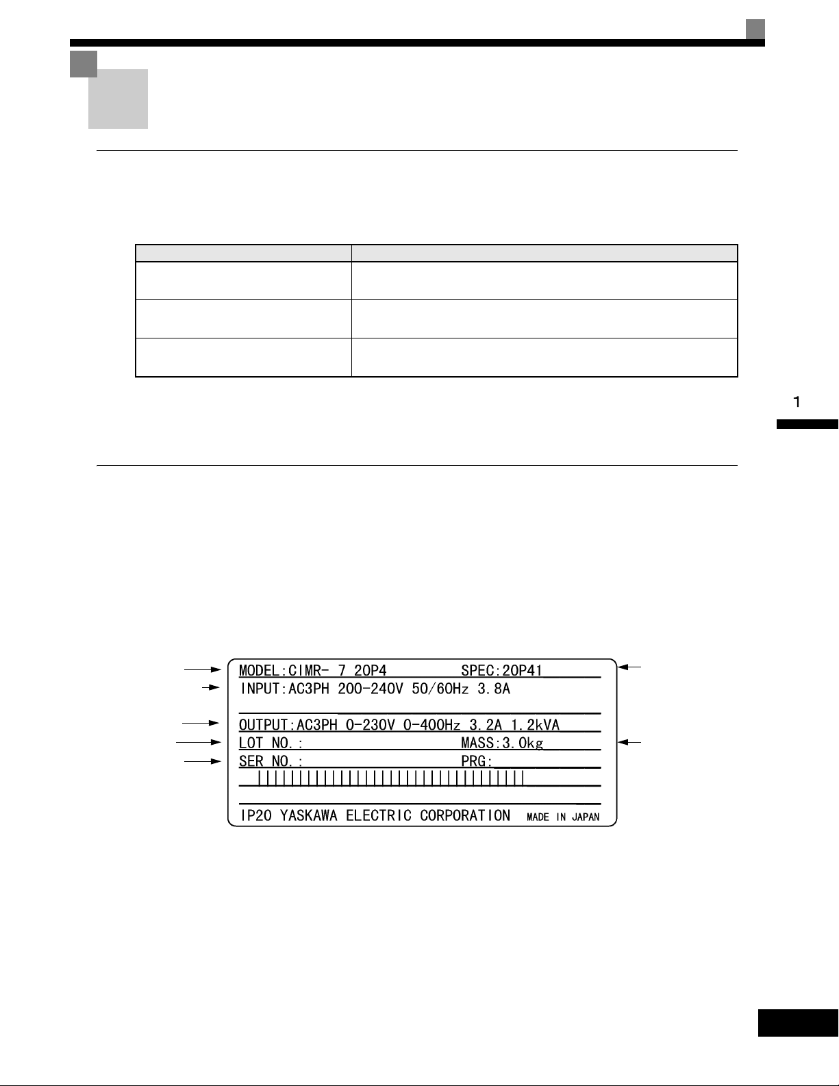
Drive model
Input specifications
Output
specifications
Lot number
Serial number
Input specifications
Drive
specifications
Mass
GU
Checks
Check the following items as soon as the Drive is delivered.
Table 1.2 Checks
Item Method
Has the correct model of Drive been
delivered?
Check the model number on the nameplate on the side of the Drive.
Confirmations upon Delivery
Is the Drive damaged in any way?
Are any screws or other components
loose?
Inspect the entire exterior of the Drive to see if there are any scratches or
other damage resulting from shipping.
Use a screwdriver or other tools to check for tightness.
If you find any irregularities in the above items, contact the agency from which you purchased the Drive or
your Yaskawa representative immediately.
Nameplate Information
There is a nameplate attached to the side of each Drive. The nameplate shows the model number, specifications, lot number, serial number, and other information on the Drive.
Example Nameplate
The following nameplate is an example for a standard Drive: 3-phase, 200-240Vac, 0.4kW, IEC IP20 and
NEMA 1 standards.
Fig 1.1 Nameplate
1-3
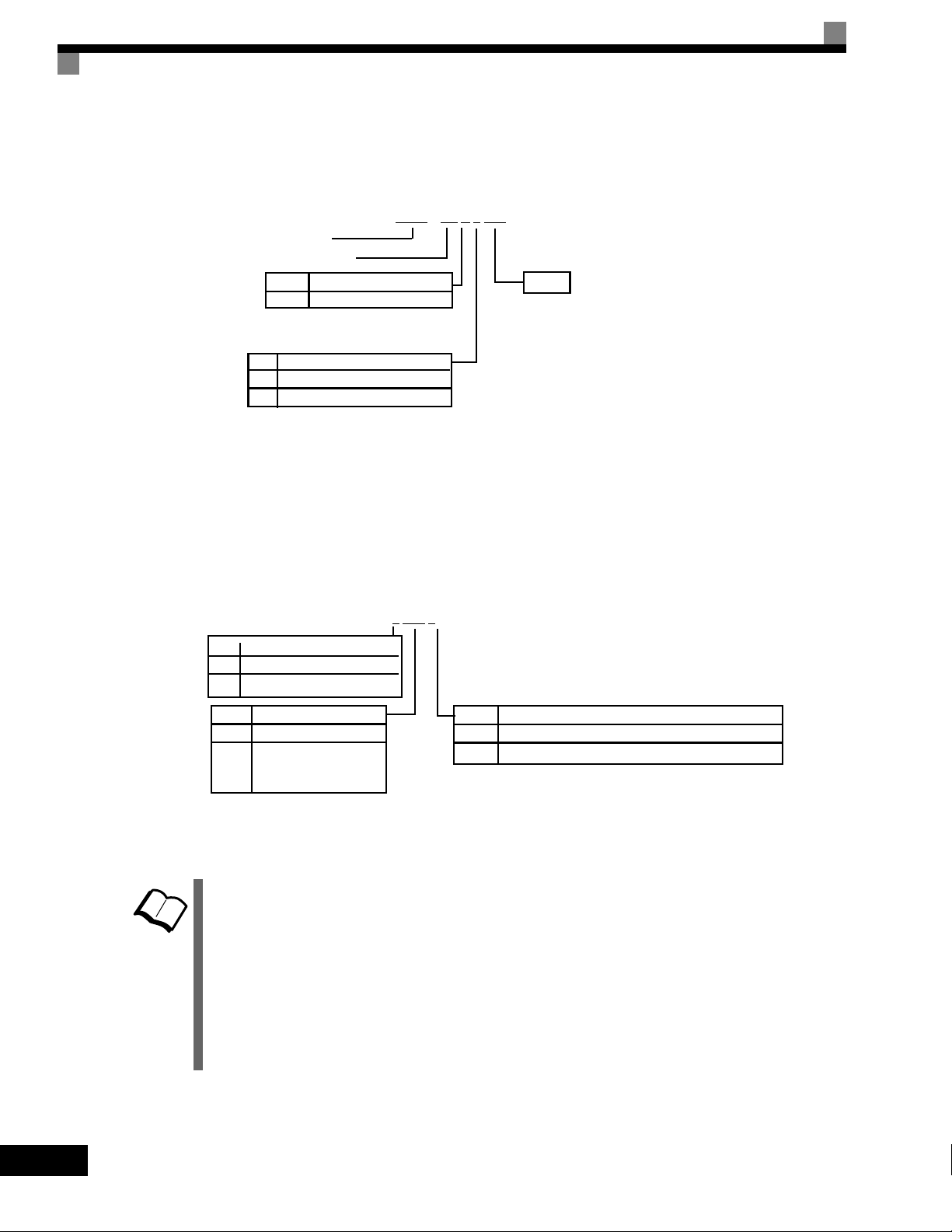
Drive Model Numbers
TERMS
No.
Spec
UL Specification
CIMR – G7 U 2 0P4
AC Drive
U
No.
Voltage
2
4
3-phase, 208-240Vac
3-phase, 480Vac
Rating
G7 Family
2 0P4 1
No.
2
4
Voltage
AC input, 3-phase, 200-240V
AC input, 3-phase, 380-480V
No.
Enclosure Type
0 Open chassis (IEC IP00)
1
NEMA Type 1 (IEC IP20)
No.
0P4 0.4kW
0P7 0.75kW
to
300kW *
to
Max. Motor Capacity
300
“P” indicates the decimal point
The model number of the Drive on the nameplate indicates the specification, voltage class, and maximum
motor capacity of the Drive in alphanumeric codes.
Fig 1.2 Drive Model Numbers
Drive Specifications
The SPEC number on the nameplate indicates the voltage, Drive rating, enclosure type, and the revision code
of the Drive in alphanumeric codes. The SPEC number for Drives that have custom features, i.e. CASE
software, will have a SPEC number that indicates the custom features installed.
1-4
Open Chassis Type (IEC IP00)
Protected so that parts of the human body cannot reach electrically charged parts from the front when the
Drive is mounted in a control panel.
NEMA Type 1 (IEC IP20)
The Drive is shielded from the exterior, and can thus be mounted to the interior wall of a standard building
(not necessarily enclosed in a control panel). The protective structure conforms to the standards of NEMA 1
in the USA.
Top protective cover must be installed to conform with IEC IP20 and NEMA 1 Type 1 requirements. Refer to
Fig. 1.4 for details.
Fig 1.3 Drive Specifications
Confirmations upon Delivery
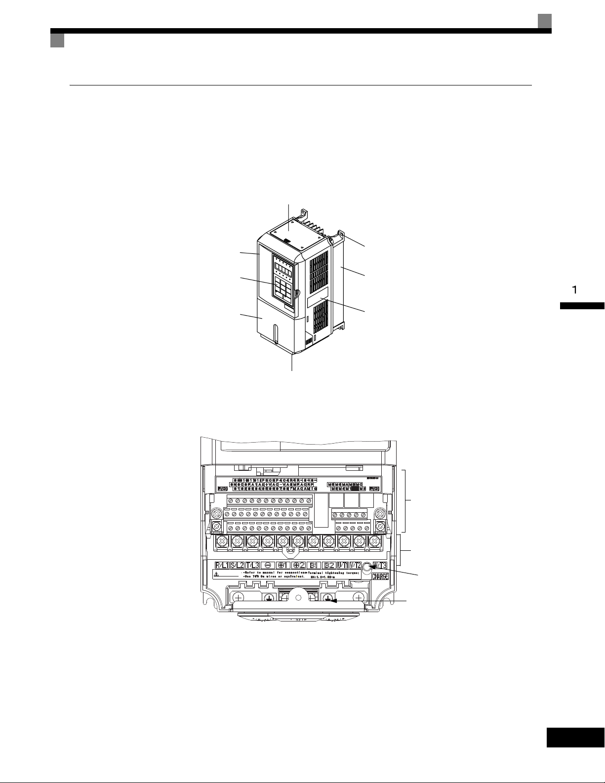
Top protective cover
[Required for NEMA Type 1 (IEC IP20)]
Front cover
Digital Operator
Terminal cover
Mounting hole
Nameplate
Bottom protective cover
Diecast case
NPJT31278-1-0NPJT31278-1-0
CAUTIONCAUTION
Charge indicator
Ground terminal
Control circuit terminals
Main circuit terminals
Component Names
Models CIMR-G7U20P4 thru 2015 and 40P4 thru 4015
The external appearance and component names of the Drive are shown in Fig 1.4. The Drive with the terminal
cover removed is shown in Fig 1.5.
Fig 1.4 Drive Appearance
Fig 1.5 Terminal Arrangement
1-5
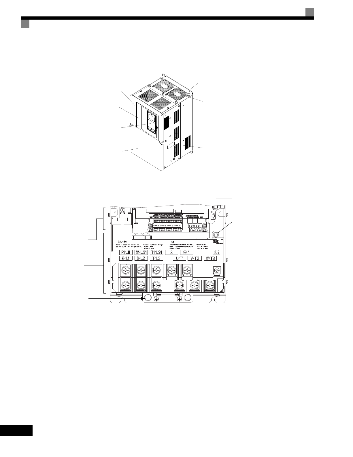
Models CIMR-G7U2018 thru 2110 and 4018 thru 4300
Mounting holes
Cooling fan
Nameplate
Drive cover
Front cover
Digital Operator
Terminal cover
Charge indicator
Control circuit
terminals
Main circuit
terminals
Ground terminal
The external appearance and component names of the Drive are shown in Fig 1.6. The Drive with the terminal
cover removed is shown in Fig 1.7.
Fig 1.6 Drive Appearance
1-6
Fig 1.7 Terminal Arrangement
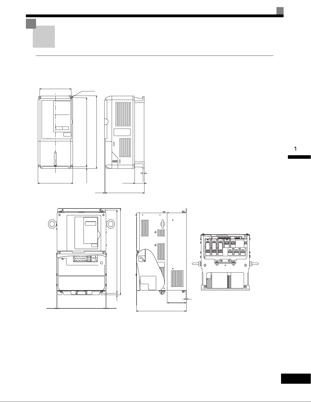
Exterior and Mounting Dimensions
W
W1
3
H1H2DH
D1
4-d
t1
Models CIMR-G7U20P4 thru 2015 and 40P4 thru 4015
D
D1
H1
H
(5)
∗
(5)
∗
H2
W
CHARGE
t1
Front View Side View Bottom View
Open Chassis Drives (IP00)
Exterior diagrams of the Open Chassis Drives are shown below.
Exterior and Mounting Dimensions
Models CIMR-G7U2018 thru 2110 and 4018 thru 4160
1-7
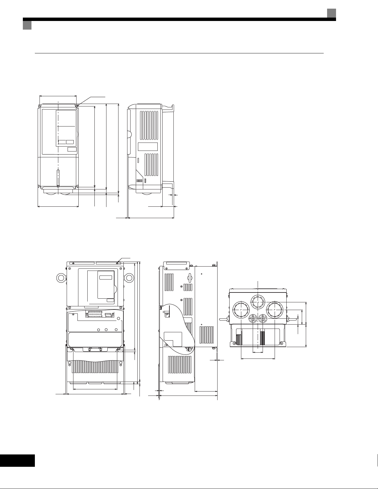
NEMA Type 1 Drives (IP 20)
W
W1
3
H1H2DH0
D1
H3
4 H
4-d
t1
Models CIMR-G7U20P4 thru 2015 and 40P4 thru 4015
(5)*
(5)
W
D
t1
H
max.10
H0
H3
H2
W1
H1
(5)*
+
-
+
D1
CHARGE
1
3
4-d
Front View Side View Bottom View
Models CIMR-G7U2018 thru 2075 and 4018 thru 4160
Exterior diagrams of the Enclosed Wall-mounted Drives (NEMA1 Type 1) are shown below.
1-8
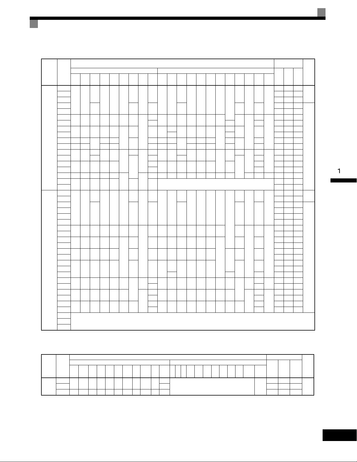
Table 1.3 Drive Dimensions (mm) and Masses (kg)
Model
Voltage
CIMR-
Class
G7U
W H D W1H1H2D1 t1
20P4
140 280
21P5 58 47 105
22P2
23P7 122 64 186
25P5
200 300 197 186 285 8 65.5
27P5 7 0 7 263 112 375
2011
240 350 207 216 335
200-240V
2015 380 30 473 174 647
(3-phase)
2018 250 400
2022 275 450 220 435 24 279 613 220 450 435 165 27 679 257 936
2030
375 600
2037 330
2045
450 725 350 325 700
2055 87 95 1474 607 2081
2075 500 850 360 370 820
2090
575 885 380 445 855 140 150 ---
2110 2389 1194 3583
40P4
40P7 21 44 65
41P5
140 280
42P2 41 49 90
43P7 77 63 140
44P0 100 66 166
45P5
200 300 197 186 285 8 65.5
47P5 197 107 304
4011
240 350 207 216 335
4015 311 135 446
4018
275 450 258 220 435 100 26 279 535 258 220 450 435
380-480V
4022 516 210 726
(3-phase)
4030
325 550 283 260 535 105 37 329
4037 737 285 1022
4045 715 165 40 929 340 1269
4055
450 725 348 325 700 12.5
4075 91 99 1554 597 2151
4090
500 850 358 370 820 15
4110 127 137 2299 928 3227
4132
575 916 378 445 855 45.8 140
4160 175 185 3614 1501 5115
4185
4300
* Same for Open Chassis and Enclosed Wall-mounted Drives
Open Chassis (IP00) Enclosed Wall-mounted (NEMA Type 1)
157
126 266 7
177 59 4 177 59 4
260
300
195 385
250 575
7.5
12.5
15 4.5
157
126 266 7
177 59 4.5 177 59 4.5
7.5
Dimensions (mm)
Approx
W H D W1H0H1H2H3D1 t1
Mass
39
78 11 240
100
100
130
3
5
6
2.3
21 254 535
57
63 328
3.2
86
140 280
126 280 266 7
200 300 197 186 300 285 8 65.5
157
350
207 216 350 335
195 400 385 135
260
380 809
298
250 600 575
453 1027 348 325 725 700 302
108 504 1243 361 370 850 820 15 393 4.5 114 M12 2009 823 2832
39
3.5
5
140 280
157
126 280 266 7
7 200 300 197 186 300 285 8 65.5
78 10 240 350 207 216 350 335
2.3
635
285 260 550 535 105
90
3.2
130
4.5
453 1027 348 325 725 700 12.5 302
109
504 1243 358 370 850 820 15 393
165
579 1324 378 445 916 855 45.8 408 140
See Table 1.44220
Exterior and Mounting Dimensions
Heat Generation
Mount-
External In ternal
ing
Holes*
3
M5
6
M6
24 599 241 840
62
68 1080 434 1514
M10
94 1291 510 1801
1660 871 2531
M5
6
M6
39
98
1239 488 1727
M10
1928 762 2690
M12
7.5
12.5
7.5
0
0
209
0
85
Approx
Mass
39
5
2.3
78 11
100
100
3.2
130
39
5
78 10
2.3
100 29
3.2
130
4.5
3.5
127
175 2612 1105 3717
(W)
Tot a l
Heat
21 36 57
83 53 136
187 87 274
357 136 493
878 362 1240
10 39 49
33 46 79
132 80 212
246 116 362
354 174 528
633 246 879
Cooling
Method
Natural20P7 43 42 85
Fan
Natural
Fan
Voltage
Class
380-
480V
(3-phase)
Table 1.4 480Vac (185 to 300 kW) Drive Dimensions (mm) and Masses (kg)
Model
CIMR-
G7U
W H D W1W2W3 H1 H2 D1 t1
4185
710 1305 413 540 240 270 1270 15 125.5 4.5
Open Chassis (IP00) Enclosed Wall-mounted (NEMA Type1)
4300 916 1475 413 730 365 365 1440 15 125.5 4.5 415 6749 2941 9690
Dimensions (mm) Heat Generation (W)
Mount-
Approx
WHDW1W2W3H1H2D1 t1
Mass
260
Approx
Mass
ing
Holes*
External Internal
4436 1995 6431
--- M12
Tot a l
Heat
Cooling
Method
Fan4220 280 5329 2205 7534
1-9
Checking and Controlling the Installation Site
Install the Drive in the installation site described below and maintain optimum conditions.
Installation Site
Install the Drive to a non-combustible surface under the following conditions in UL Pollution Degree 2 environments. This excludes wet locations where pollution may become conductive due to moisture, and locations
containing conductive foreign matter
Table 1.5 Installation Site
Type Ambient Operating Temperature Humidity
NEMA Type 1 14° F-to- 104°F (-10-to- + 40 °C) 95% RH or less (no condensation)
Open chassis 14° F-to- 113°F (-10-to- + 45 °C) 95% RH or less (no condensation)
Protective covers are attached to the top and bottom of the Drive. It is recommended to remove the protective
covers before operating a NEMA Type 1 Drive (Models CIMR-G7U2015/4015 and smaller) in a panel to
obtain the 113° (45°C) ambient operating temperature.
Observe the following precautions when installing the Drive. Make sure to install:
• In a clean location which is free from oil mist and dust.
• In an environment where metal shavings, oil, water, or other foreign materials do not get into the Drive.
• In a location free from radioactive materials and combustible materials (e.g. wood).
• In a location free from harmful gases and liquids.
• In a location free from excessive vibration.
• In a location free from chlorides
• In a location away from direct sunlight.
1-10
Controlling the Ambient Temperature
To enhance the reliability of operation, the Drive should be installed in an environment free from extreme temperature variation. If the Drive is installed in an enclosure, use a cooling fan or air conditioner to maintain the
internal air temperature below 113°
F (45°C).
Protecting the Drive from Foreign Matter
During Drive installation and project construction, it is possible to have foreign matter such as metal shavings
or wire clippings fall inside the Drive. To prevent foreign matter from falling into the Drive, place a temporary
cover over the Drive.
Always remove the temporary cover from the Drive before start-up. Otherwise, ventilation will be reduced,
causing the Drive to overheat.
Installation Orientation and Space
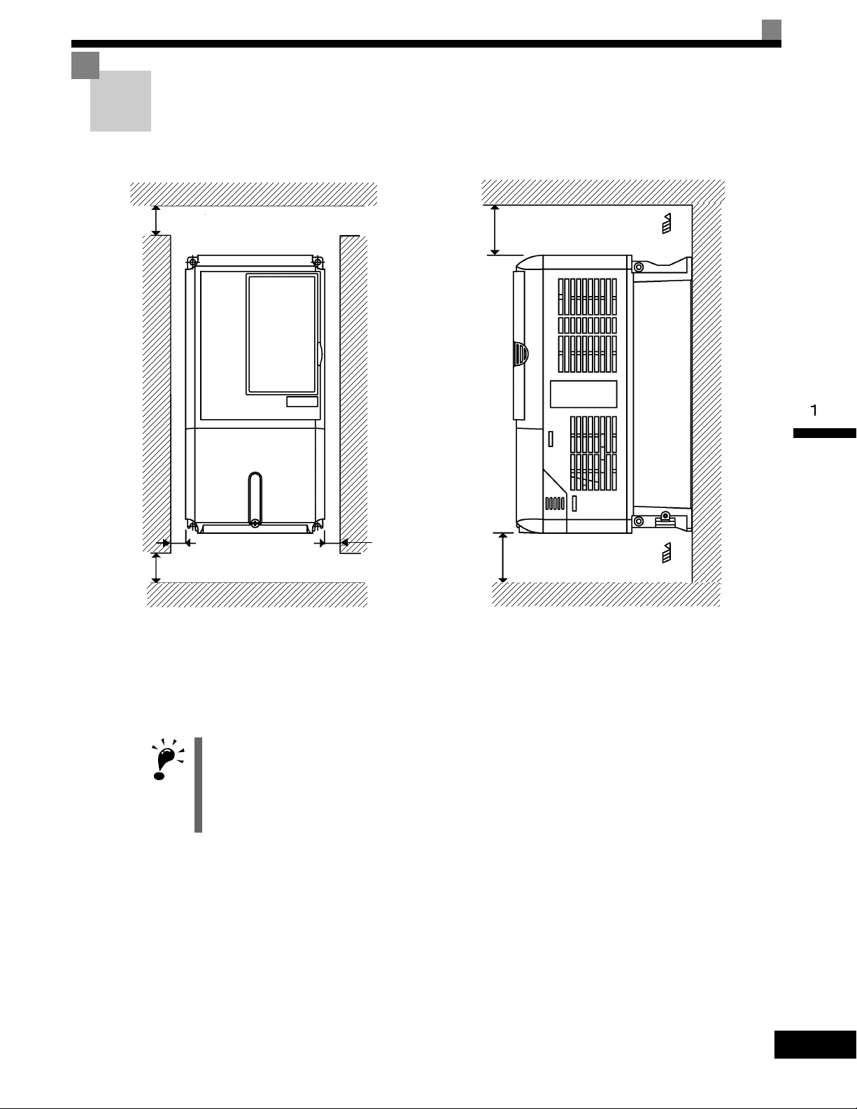
IMPORTANT
4.72in (120mm) minimum
4.75in (120mm) minimum
Air
Air
Vertical ClearanceHorizontal Clearance
1.2in
(30.5mm) minimum
1.2in
(30.5mm) minimum
1.97in (50mm) minimum
1.97in * (50mm) minimum
* For Drive model G7U4300, this clearance dimension is 11.81in (300mm) minimum. All other models require 1.97in (50mm) minimum.
Install the Drive vertically so as not to reduce the cooling effect. When installing the Drive, always provide the following installation space to allow normal heat dissipation.
Installation Orientation and Space
Fig 1.8 Drive Installation Orientation and Space
1. The same space is required horizontally and vertically for both Open Chassis (IP00) and Enclosed Wallmounted (IP20, NEMA 1 Type 1) Drives.
2. Always remove the protection covers before installing a 200-240 or 380-480 V Class Drive with an output
of 15 kW or less in a panel.
Always provide enough space for suspension eye bolts and the main circuit lines when installing a 200-240
or 380-480 V Class Drive with an output of 18.5 kW or more in a panel.
1-11
Removing and Attaching the Terminal Cover
1
2
1
1
2
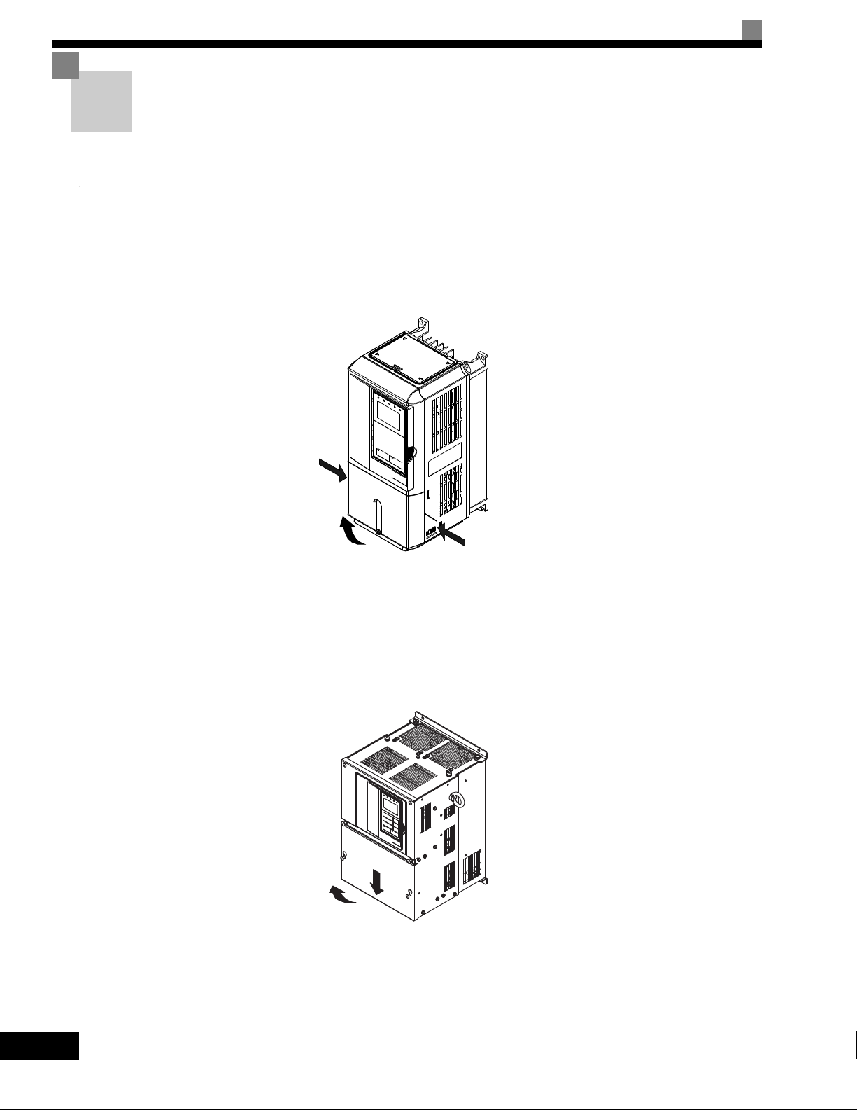
Remove the terminal cover to wire cables to the control circuit and main circuit terminals.
Removing the Terminal Cover
Models CIMR-G7U20P4 thru 2015 and 40P4 thru 4015
Loosen the screws at the bottom of the terminal cover, press in on the sides of the terminal cover in the
directions of arrows 1, and then lift up on the terminal in the direction of arrow 2.
Fig 1.9 Removing the Terminal Cover (Model CIMR-G7U23P7 Shown Above)
Models CIMR-G7U2018 thru 2110 and 4018 thru 4300
Loosen the screws on the left and right at the top of the terminal cover, pull out the terminal cover in the
direction of arrow 1 and then lift up on the terminal in the direction of arrow 2.
Fig 1.10 Removing the Terminal Cover (Model CIMR-G7U2018 Shown Above)
1-12

Removing and Attaching the Terminal Cover
Attaching the Terminal Cover
After wiring the terminal block, attach the terminal cover by reversing the removal procedure.
For Models CIMR-G7U2015/4015 and smaller, insert the tab on the top of the terminal cover into the groove on the
Drive, and press in on the bottom of the terminal cover until it clicks into place.
For Drives CIMR-G7U2018/4018 and larger, insert the tab on the top of the terminal cover into the groove on the
Drive, and secure the terminal cover by lifting it up toward the top of the Drive.
1-13
Removing/Attaching the Digital Operator and
1
2
Front Cover
The methods of removing and attaching the Digital Operator and Front Cover are described in this section.
Models CIMR-G7U20P4 thru 2015 and 40P4 thru 4015
To attach optional cards or change the terminal card connector, remove the Digital Operator and front cover in
addition to the terminal cover. Always remove the Digital Operator from the front cover before removing the
terminal cover.
The removal and attachment procedures are given below.
Removing the Digital Operator
Press the lever on the side of the Digital Operator in the direction of arrow 1 to unlock the Digital Operator
and lift the Digital Operator in the direction of arrow 2 to remove the Digital Operator as shown in the following illustration.
1-14
Fig 1.11 Removing the Digital Operator (Model CIMR-G7U43P7 Shown Above)
Removing/Attaching the Digital Operator and Front Cover
1
1
2
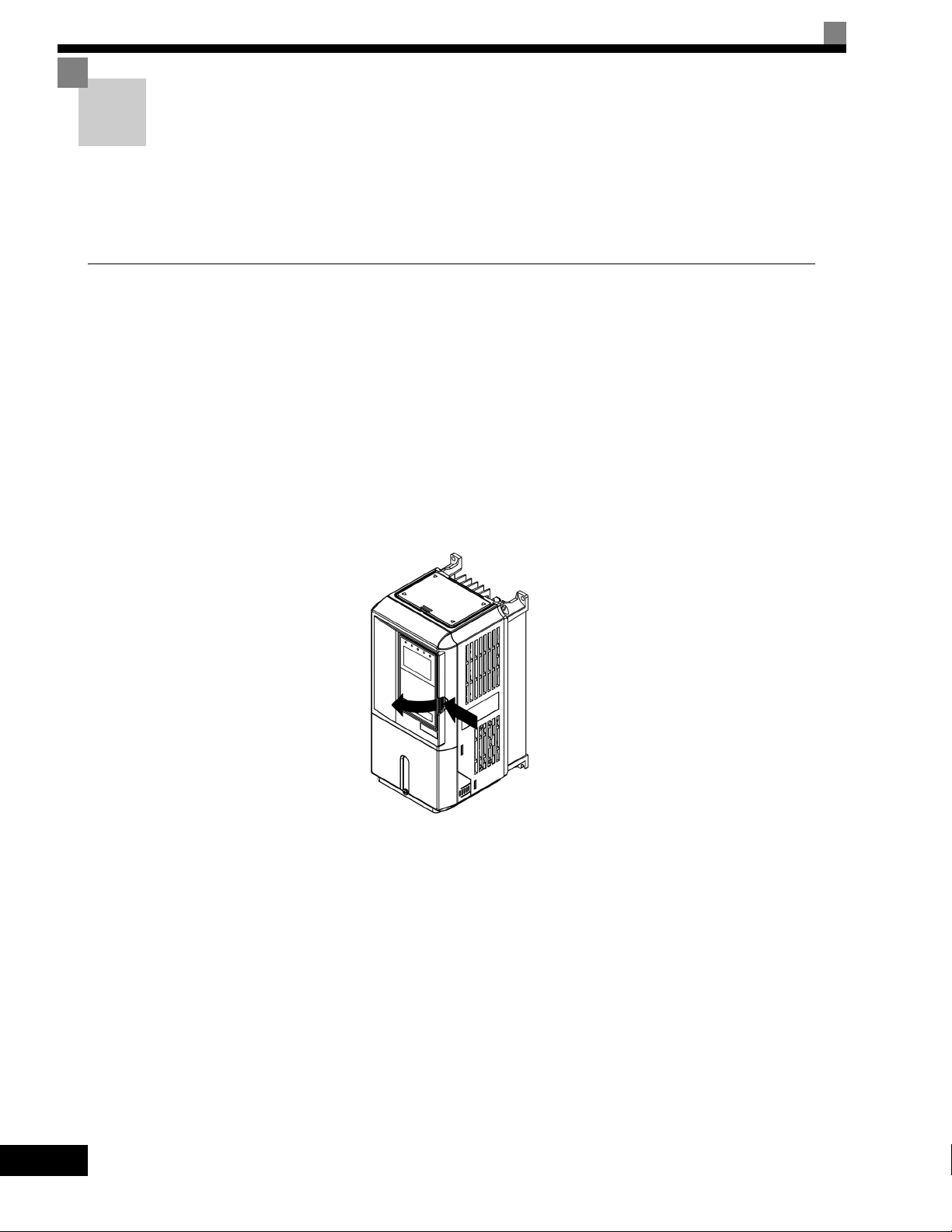
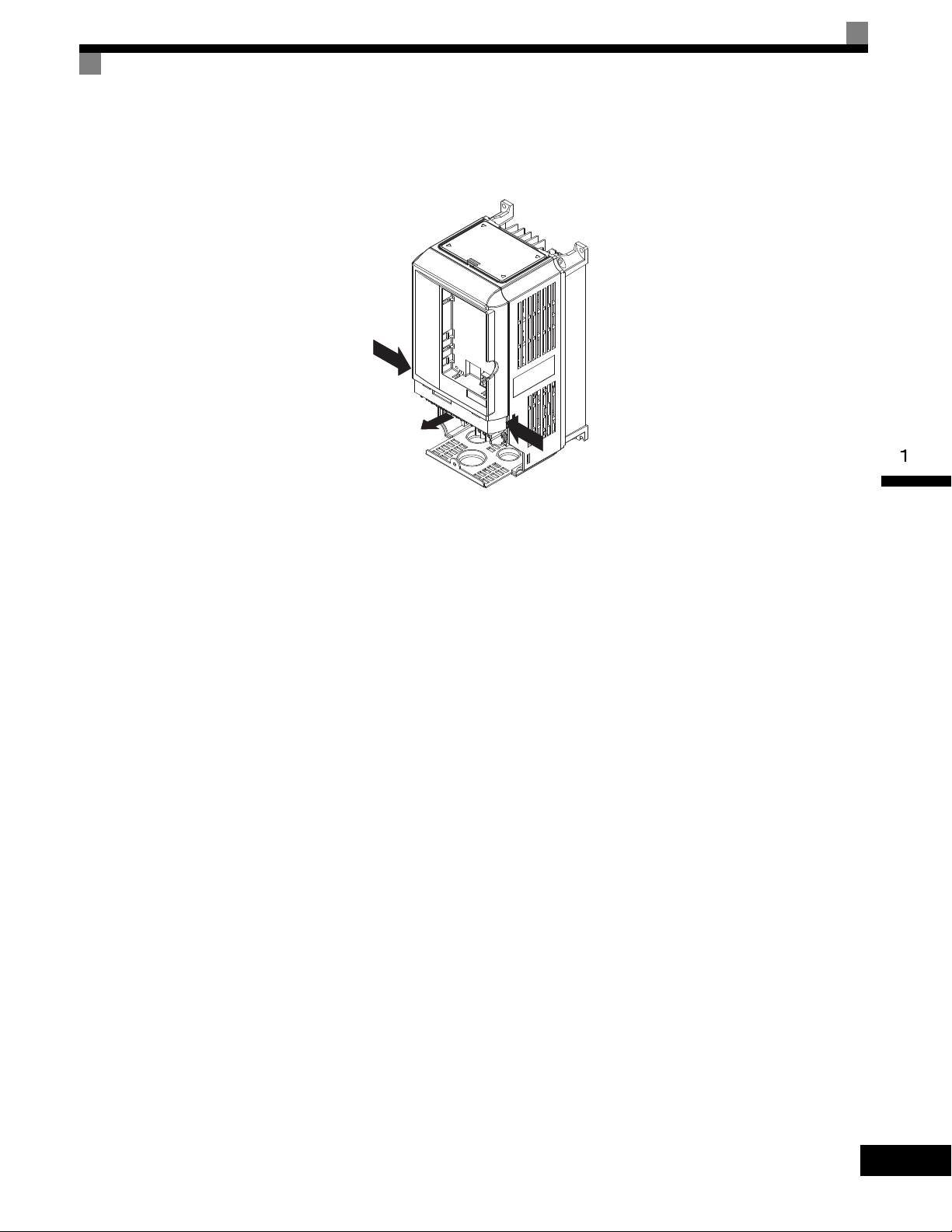
Removing the Front Cover
Press the left and right sides of the front cover in the directions of arrows 1 and lift the bottom of the cover in
the direction of arrow 2 to remove the front cover as shown in Fig. 1.12.
Fig 1.12 Removing the Front Cover (Model CIMR-G7U43P7 Shown Above)
Mounting the Front Cover
After wiring the terminals, mount the front cover to the Drive by performing in reverse order to the steps to
remove the front cover.
1. Do not mount the front cover with the Digital Operator attached to the front cover; otherwise, Digital
Operator may malfunction due to improper mating with control board connector.
2. Insert the tab of the upper part of the front cover into the groove of the Drive and press the lower part of the
front cover onto the Drive until the front cover snaps into place.
1-15
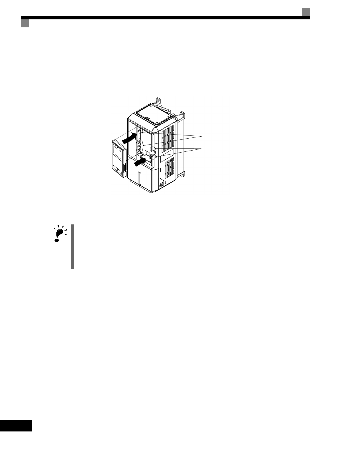
Mounting the Digital Operator
IMPORTANT
A
B
1
2
After attaching the front cover, mount the Digital Operator onto theDrive using the following procedure.
1. Hook the Digital Operator at A (two locations) on the left side of the opening on the front cover in the
direction of arrow 1 as shown in the following illustration.
2. Press the Digital Operator in the direction of arrow 2 until it snaps in place at B (two locations).
Fig 1.13 Mounting the Digital Operator
1. Do not remove or attach the Digital Operator or mount or remove the front cover using methods other than
those described above, otherwise the Drive may break or malfunction due to imperfect contact.
2. Never attach the front cover to the Drive with the Digital Operator attached to the front cover. Imperfect
contact can result.
Always attach the front cover to the Drive by itself first, and then attach the Digital Operator to the front
cover.
1-16
Removing/Attaching the Digital Operator and Front Cover
1
2
Models CIMR-G7U2018 thru 2110 and 4018 thru 4300
For Drive models CIMR-G7U2018 thru 2110 and 4018 thru 4300, remove the terminal cover and then use the
following procedures to remove the Digital Operator and main cover.
Removing the Digital Operator
Use the same procedure as for Drives with an output of 18.5 kW or less.
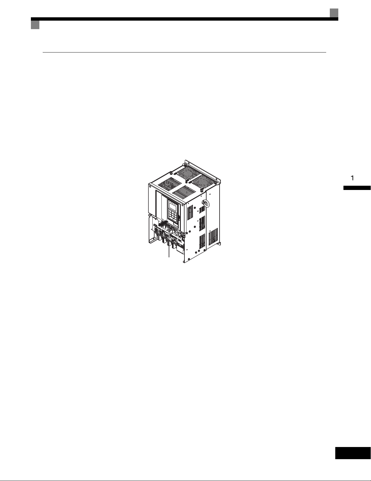
Removing the Front Cover
Loosen all screws on the front cover. Lift up at the location labelled 1 at the top of the control circuit terminal
card and move in the direction of arrow 2.
Fig 1.14 Removing the Front Cover (Model CIMR-G7U2018 Shown Above)
Attaching the Front Cover
Attach the front cover by reversing the procedure to remove it.
1. Confirm that the Digital Operator is not mounted on the front cover. If the cover is attached while the
Digital Operator is mounted to it, the Digital Operator may malfunction due to improper mating with its
connector.
2. Insert the tab on the top of the front cover into the slot on the Drive and press in on the cover until it clicks
into place on the Drive.
Attaching the Digital Operator
Use the same procedure as for Drives with an output of 18.5 kW or less.
1-17
Loading...