


 Loading...
POWER AMPLIFIER
Owner’s Manual
Bedienungsanleitung Mode d’emploi
Manual de instrucciones Manuale di istruzioni Руководство пользователя
EN
DE
FR
ES
IT
RU
ZH
JA
Русский Italiano Español Français Deutsch English
CAUTION
RISK OF ELECTRIC SHOCK
DO NOT OPEN
CAUTION: TO REDUCE THE RISK OF ELECTRIC SHOCK, DO NOT REMOVE COVER (OR BACK). NO USER-SERVICEABLE PARTS INSIDE. REFER SERVICING TO QUALIFIED SERVICE PERSONNEL.
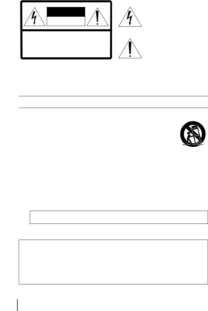
The above warning is located on the top of the unit.
Explanation of Graphical Symbols
The lightning flash with arrowhead symbol within an equilateral triangle is intended to alert the user to the presence of uninsulated “dangerous voltage” within the product’s enclosure that may be of sufficient magnitude to constitute a risk of electric shock to persons.
The exclamation point within an equilateral triangle is intended to alert the user to the presence of important operating and maintenance (servicing) instructions in the literature accompanying the product.
IMPORTANT SAFETY INSTRUCTIONS
1 Read these instructions.
2 Keep these instructions.
3Heed all warnings.
4Follow all instructions.
5 Do not use this apparatus near water.
6Clean only with dry cloth.
7Do not block any ventilation openings. Install in
accordance with the manufacturer’s instructions.
8Do not install near any heat sources such as radiators, heat registers, stoves, or other apparatus (including amplifiers) that produce heat.
9Do not defeat the safety purpose of the polarized or grounding-type plug. A polarized plug has two blades with one wider than the other. A grounding type plug has two blades and a third grounding prong. The wide blade or the third prong are provided for your safety. If the provided plug does not fit into your outlet, consult an electrician for replacement of the
obsolete outlet.
10Protect the power cord from being walked on or pinched particularly at plugs, convenience receptacles, and the point where they exit from the apparatus.
11Only use attachments/accessories specified by the manufacturer.
12Use only with the cart, stand, tripod, bracket, or table speci-
fied by the manufacturer, or sold with the apparatus. When a cart is used, use caution when moving the cart/apparatus combination to avoid injury from tip-over.
13Unplug this apparatus during lightning storms or when unused for long periods of time.
14Refer all servicing to qualified service personnel. Servicing is required when the apparatus has been damaged in any way, such as power-supply cord or plug is damaged, liquid has been spilled or objects have fallen into the apparatus, the apparatus has been exposed to rain or moisture, does not operate normally, or has been dropped.
WARNING
TO REDUCE THE RISK OF FIRE OR ELECTRIC SHOCK, DO NOT EXPOSE THIS APPARATUS TO RAIN OR MOISTURE.
(UL60065_03)
ADVARSEL!
Lithiumbatteri—Eksplosionsfare ved fejlagtig håndtering. Udskiftning må kun ske med batteri af samme fabrikat og type. Levér det brugte batteri tilbage til leverandoren.
VARNING
Explosionsfara vid felaktigt batteribyte. Använd samma batterityp eller en ekvivalent typ som rekommenderas av apparattillverkaren. Kassera använt batteri enligt fabrikantens instruktion.
VAROITUS
Paristo voi räjähtää, jos se on virheellisesti asennettu. Vaihda paristo ainoastaan laitevalmistajan suosittelemaan tyyppiin. Hävitä käytetty paristo valmistajan ohjeiden mukaisesti.
(lithium caution)
2 XMV4280/XMV4140 Owner’s Manual

|
FCC INFORMATION (U.S.A.) |
|
|
|
1. |
IMPORTANT NOTICE: DO NOT MODIFY THIS UNIT! |
all installations. If this product is found to be the source of |
|
|
|
||||
|
This product, when installed as indicated in the instructions |
interference, which can be determined by turning the unit |
|
|
|
contained in this manual, meets FCC requirements. Modifi- |
“OFF” and “ON”, please try to eliminate the problem by using |
|
|
|
cations not expressly approved by Yamaha may void your |
one of the following measures: |
|
|
|
authority, granted by the FCC, to use the product. |
Relocate either this product or the device that is being |
|
|
2. IMPORTANT: When connecting this product to accessories |
affected by the interference. |
|
|
|
|
and/or another product use only high quality shielded cables. |
Utilize power outlets that are on different branch (circuit |
|
|
|
Cable/s supplied with this product MUST be used. Follow all |
breaker or fuse) circuits or install AC line filter/s. |
|
|
|
installation instructions. Failure to follow instructions could |
In the case of radio or TV interference, relocate/reorient the |
|
|
|
|
|
||
|
void your FCC authorization to use this product in the USA. |
antenna. If the antenna lead-in is 300 ohm ribbon lead, |
|
|
3. NOTE: This product has been tested and found to comply |
|
|
||
change the lead-in to co-axial type cable. |
|
|
||
|
with the requirements listed in FCC Regulations, Part 15 for |
If these corrective measures do not produce satisfactory |
|
|
|
Class “B” digital devices. Compliance with these require- |
|
|
|
|
results, please contact the local retailer authorized to distrib- |
|
|
|
|
ments provides a reasonable level of assurance that your |
|
|
|
|
ute this type of product. If you can not locate the appropriate |
|
|
|
|
use of this product in a residential environment will not result |
|
|
|
|
retailer, please contact Yamaha Corporation of America, |
|
|
|
|
in harmful interference with other electronic devices. This |
|
|
|
|
Electronic Service Division, 6600 Orangethorpe Ave, Buena |
|
|
|
|
equipment generates/uses radio frequencies and, if not |
|
|
|
|
Park, CA90620 |
|
|
|
|
installed and used according to the instructions found in the |
|
|
|
|
The above statements apply ONLY to those products distrib- |
|
|
|
|
users manual, may cause interference harmful to the opera- |
|
|
|
|
uted by Yamaha Corporation of America or its subsidiaries. |
|
|
|
|
tion of other electronic devices. Compliance with FCC regu- |
|
|
|
|
|
|
|
|
|
lations does not guarantee that interference will not occur in |
|
|
|
|
|
|
|
|
* This applies only to products distributed by YAMAHA CORPORATION OF AMERICA. |
(class B) |
|
||
|
|
|
|
|
COMPLIANCE INFORMATION STATEMENT (DECLARATION OF CONFORMITY PROCEDURE)
Responsible Party : Yamaha Corporation of America
Address : 6600 Orangethorpe Ave., Buena Park,
Calif. 90620
Telephone : 714-522-9011
Type of Equipment : Power Amplifier
Model Name : XMV4280/XMV4140
This device complies with Part 15 of the FCC Rules. Operation is subject to the following two conditions:
1)this device may not cause harmful interference, and
2)this device must accept any interference received including interference that may cause undesired operation.
See user manual instructions if interference to radio reception is suspected.
* This applies only to products distributed by |
(FCC DoC) |
YAMAHA CORPORATION OF AMERICA. |
|
IMPORTANT NOTICE FOR THE UNITED KINGDOM
Connecting the Plug and Cord
WARNING: THIS APPARATUS MUST BE EARTHED IMPORTANT. The wires in this mains lead are coloured in accordance with the following code:
GREEN-AND-YELLOW : EARTH
BLUE |
: |
NEUTRAL |
BROWN |
: |
LIVE |
As the colours of the wires in the mains lead of this apparatus may not correspond with the coloured markings identifying the terminals in your plug proceed as follows:
The wire which is coloured GREEN-and-YELLOW must be connected to the terminal in the plug which is marked by the letter E or by the safety earth symbol  or colored GREEN or GREEN-and-YELLOW.
The wire which is coloured BLUE must be connected to the terminal which is marked with the letter N or coloured BLACK.
The wire which is coloured BROWN must be connected to the terminal which is marked with the letter L or coloured RED.
(3 wires)
In Finland: Laite on liitettävä suojamaadoituskoskettimilla varustettuun pistorasiaan. In Norway: Apparatet må tilkoples jordet stikkontakt.
In Sweden: Apparaten skall anslutas till jordat uttag.
(class I hokuo)
This product contains a battery that contains perchlorate material.
Perchlorate Material—special handling may apply,
See www.dtsc.ca.gov/hazardouswaste/perchlorate.
* This applies only to products distributed by YAMAHA CORPORATION OF AMERICA. |
(Perchlorate) |
(B ), .
(class b korea)
XMV4280/XMV4140 Owner’s Manual 3

PRECAUTIONS
PLEASE READ CAREFULLY BEFORE PROCEEDING
* Please keep this manual in a safe place for future reference.
 WARNING
Always follow the basic precautions listed below to avoid the possibility of serious injury or even death from electrical shock, short-circuiting, damages, fire or other hazards. These precautions include, but are not limited to, the following:
Power supply/Power cord
•Do not place the power cord near heat sources such as heaters or radiators, and do not excessively bend or otherwise damage the cord, place heavy objects on it, or place it in a position where anyone could walk on, trip over, or roll anything over it.
•Only use the voltage specified as correct for the device. The required voltage is printed on the name plate of the device.
•Use only the supplied power cord/plug.
If you intend to use the device in an area other than in the one you purchased, the included power cord may not be compatible. Please check with your Yamaha dealer.
•Check the electric plug periodically and remove any dirt or dust which may have accumulated on it.
•Be sure to connect to an appropriate outlet with a protective grounding connection. Improper grounding can result in electrical shock.
Do not open
•This device contains no user-serviceable parts. Do not open the device or attempt to disassemble the internal parts or modify them in any way. If it should appear to be malfunctioning, discontinue use immediately and have it inspected by qualified Yamaha service personnel.
Water warning
•Do not expose the device to rain, use it near water or in damp or wet conditions, or place on it any containers (such as vases, bottles or glasses) containing liquids which might spill into any openings. If any liquid such as water seeps into the device, turn off the power immediately and unplug the power cord from the AC outlet. Then have the device inspected by qualified Yamaha service personnel.
•Never insert or remove an electric plug with wet hands.
Fire warning
•Do not put burning items, such as candles, on the unit. A burning item may fall over and cause a fire.
If you notice any abnormality
•When one of the following problems occur, immediately turn off the power switch and disconnect the electric plug from the outlet. Then have the device inspected by Yamaha service personnel.
-The power cord or plug becomes frayed or damaged.
-It emits unusual smells or smoke.
-Some object has been dropped into the instrument.
-There is a sudden loss of sound during use of the device.
•If this device should be dropped or damaged, immediately turn off the power switch, disconnect the electric plug from the outlet, and have the device inspected by qualified Yamaha service personnel.
 CAUTION
Always follow the basic precautions listed below to avoid the possibility of physical injury to you or others, or damage to the device or other property. These precautions include, but are not limited to, the following:
Power supply/Power cord
•When removing the electric plug from the device or an outlet, always hold the plug itself and not the cord. Pulling by the cord can damage it.
•Remove the electric plug from the outlet when the device is not to be used for extended periods of time, or during electrical storms.
Location
•Do not place the device in an unstable position where it might accidentally fall over.
•Do not block the vents. This device has ventilation holes at the front/rear/ side to prevent the internal temperature from becoming too high. In particular, do not place the device on its side or upside down. Inadequate ventilation can result in overheating, possibly causing damage to the device(s), or even fire.
•Do not use the device in a confined, poorly-ventilated location. If this device is to be used in a small space other than an EIA-standard rack, make sure that there is adequate space between the device and surrounding walls or other devices: at least 10 cm at the sides, 10 cm behind and 40 cm above. Inadequate ventilation can result in overheating, possibly causing damage to the device(s), or even fire.
•Do not place the device in a location where it may come into contact with corrosive gases or salt air. Doing so may result in malfunction.
•Before moving the device, remove all connected cables.
•When setting up the device, make sure that the AC outlet you are using is easily accessible. If some trouble or malfunction occurs, immediately turn off the power switch and disconnect the plug from the outlet. Even when the power switch is turned off, electricity is still flowing to the product at the minimum level. When you are not using the product for a long time, make sure to unplug the power cord from the wall AC outlet.
•If the device is mounted in an EIA standard rack, carefully read the section “Precautions for Rack Mounting” on page 7. Inadequate ventilation can result in overheating, possibly causing damage to the device(s), malfunction, or even fire.
Connections
•Before connecting the device to other devices, turn off the power for all devices. Before turning the power on or off for all devices, set all volume levels to minimum.
•Use only speaker cables for connecting speakers to the speaker connectors. Use of other types of cables may result in fire.
Maintenance
• Remove the power plug from the AC outlet when cleaning the device.
4 |
|
XMV4280/XMV4140 Owner’s Manual |
PA_en_1 1/2 |
|
|||
|
|
|
|
Handling caution |
|
Backup battery |
•Do not insert your fingers or hands in any gaps or openings on the device (vents).
•Avoid inserting or dropping foreign objects (paper, plastic, metal, etc.) into any gaps or openings on the device (vents) If this happens, turn off the power immediately and unplug the power cord from the AC outlet. Then have the device inspected by qualified Yamaha service personnel.
•Do not rest your weight on the device or place heavy objects on it, and avoid use excessive force on the buttons, switches or connectors.
•Do not use speakers for a long period of time at a high or uncomfortable volume level, since this can cause permanent hearing loss. If you experience any hearing loss or ringing in the ears, consult a physician.
•This device has a built-in backup battery. When you unplug the power cord from the AC outlet, the internal data is retained. However, if the backup battery fully discharges, this data will be lost. When the backup battery is running low, the display indicates “010.” or “011.” and the ALERT indicator is blinking. In this case, immediately save the data to external device such as a computer, then have qualified Yamaha service personnel replace the backup battery.
Yamaha cannot be held responsible for damage caused by improper use or modifications to the device, or data that is lost or destroyed.
Always turn the power off when the device is not in use.
European Models
Inrush Current based on EN 55103-1:2009 10A (on initial switch-on)
5A (after a supply interruption of 5s) Conforms to Environments: E1, E2, E3 and E4
NOTICE
To avoid the possibility of malfunction/ damage to the product, damage to data, or damage to other property, follow the notices below.
Handling and Maintenance
•Do not use the device in the vicinity of a TV, radio, stereo equipment, mobile phone, or other electric devices. Otherwise, the device, TV, or radio may generate noise.
•Do not expose the device to excessive dust or vibration, or extreme cold or heat (such as in direct sunlight, near a heater, or in a car during the day), in order to prevent the possibility of panel disfiguration, unstable operation, or damage to the internal components.
•Do not place vinyl, plastic or rubber objects on the device, since this might discolor the panel.
•When cleaning the device, use a dry and soft cloth. Do not use paint thinners, solvents, cleaning fluids, or chemical-impregnated wiping cloths.
•Condensation can occur in the device due to rapid, drastic changes in ambient temperature—when the device is moved from one location to another, or air conditioning is turned on or off, for example. Using the device while condensation is present can cause damage. If there is reason to believe that condensation might have occurred, leave the device for several hours without turning on the power until the condensation has completely dried out.
•Do not use this device for any purpose other than driving loudspeakers.
•When turning on the AC power in your audio system, always turn on tthe device LAST, to avoid speaker damage. When turning the power off, the device should be turned off FIRST for the same reason.
•Always turn the power off when the device is not in use.
Saving data
This device has a built-in backup battery that maintains data in internal memory even when the device’s power is switched off. The backup battery will eventually become depleted, however, and when that happens the contents of the internal memory will be lost.* To prevent loss of data be sure to replace the backup battery before it becomes fully depleted. When the remaining capacity of the backup battery becomes so low that it needs to be replaced a “010.” or “011.” message will appear on the display during operation or when the device is powered on. If either of these messages appears do not turn off the power and immediately transfer any data you want to save to a computer or other external storage device, then have qualified Yamaha service personnel replace the backup battery. The average life of the internal backup battery is approximately 5 years, depending on operating conditions.
*Data items maintained in the internal memory by the backup battery are as follows:
•Device parameters (Attenuator values, Polarity settings, HPF settings, Analog/digital input setting, and [SIGNAL] indicator display setting).
•Event log.
Information
About this manual
•The illustrations as shown in this manual are for instructional purposes only, and may appear somewhat different from those on your device.
•The company names and product names in this manual are the trademarks or registered trademarks of their respective companies.
PA_en_1 2/2 |
XMV4280/XMV4140 Owner’s Manual |
|
5 |
|
|||
|
|
|
|

Contents
Introduction..................................................................................................................... |
7 |
Features.................................................................................................................................. |
7 |
Related manuals and software................................................................................................ |
7 |
Firmware Updates................................................................................................................... |
7 |
Precautions for Rack Mounting ........................................................................................ |
7 |
Controls and Functions ................................................................................................. |
8 |
Front Panel.............................................................................................................................. |
8 |
Rear Panel ............................................................................................................................ |
10 |
Setup.............................................................................................................................. |
13 |
Using and connecting the [REMOTE] connector and |
|
[FAULT OUTPUT] connector ...................................................................................... |
18 |
Using the [REMOTE] connector (Euroblock 3-pin) ............................................................... |
18 |
Using the [FAULT OUTPUT] connector (Euroblock 3-pin) .................................................... |
18 |
Connecting the [REMOTE] connector or [FAULT OUTPUT] connector ................................ |
19 |
List of Front Panel Operations .................................................................................... |
20 |
Initializing the Internal Memory................................................................................... |
22 |
Troubleshooting ........................................................................................................... |
23 |
Alert Numbers and Content......................................................................................... |
24 |
High-impedance and Low-impedance Connections ................................................. |
25 |
Multiple Speaker System Drive Capability ............................................................................ |
25 |
Transmission Distance and Efficiency................................................................................... |
26 |
Specifications ............................................................................................................. |
201 |
XMV4280/XMV4140 Block Diagram ........................................................................... |
203 |
Dimensions ................................................................................................................. |
203 |
Current Draw............................................................................................................... |
204 |
Included items (please check)
•Owner’s Manual
•Power cord
•Euroblock plugs (3-pin) x 2
•Euroblock plugs with tabs (3-pin) x 4
•Cable ties x 4
6 XMV4280/XMV4140 Owner’s Manual

Introduction
Thank you for your purchase of the Yamaha XMV4280 or XMV4140 power amplifier. Please read through this manual carefully before beginning use, so that you will be able to take full advantage of your power amplifier’s superlative features and enjoy trouble-free operation for years to come. After you have read the manual, keep it in a safe place for reference when needed.
NOTE
•When there are differences in the specifications of the XMV4280 and the XMV4140, this manual will use curly brackets { } to enclose information that applies only to the XMV4140.
(Example: 280W {140W}).
•Unless otherwise specified, illustrations are taken from the XMV4280.
Features
The XMV is a multi-channel power amplifier with the following features.
•Both high-impedance and low-impedance connections are supported
Both high-impedance connections to 70V/100V lines and 4Ω/8Ω low-impedance connections are supported. A rear panel DIP switch allows this setting to be specified for every two channels.
•Newly-developed “Double Power mode”
The newly-developed “Double Power mode” doubles the amplifier output of each channel when low-impedance connections are used.
* The number of available channels will be halved.
•Settings can be made via application software
Although settings such as mute on/off and attenuator values can be edited from the panel of the amplifier itself, you can use an MTX series matrix processor and computer to edit the settings of multiple XMV units.
•Support for the newly-developed “YDIF” digital audio transmission format
This allows up to 16 channels of audio and word clock to be transmitted and received via an Ethernet cable.
This model can receive four channels of audio signals via YDIF.
•High efficiency
The newly-developed output circuits allows high efficiency.
Related manuals and software
You can easily configure a complete sound system featuring the XMV by connecting it to MTX series matrix processors or to MTX Editor system configuration software. The owner’s manual for the MTX and for MTX Editor, and MTX Editor itself (subsequently referred to as “the editor”) can be downloaded from the download page of the following website.
http://www.yamahaproaudio.com/
• List of related manuals
MTX3 Owner’s |
This explains how to use the MTX3 |
|
Manual |
matrix processor. |
|
|
|
|
MTX Editor User’s |
This explains how to use MTX Editor. |
|
Manual |
||
|
||
|
|
|
|
This explains how to use and set up |
|
MTX Setup Manual |
the MTX3 matrix processor that is |
|
|
used along with the XMV power amp. |
|
|
|
NOTE
In order to view the downloaded manuals, Adobe Reader must be installed in your computer. If you don’t have Adobe Reader, please access the Adobe Corporation’s website at the following URL, and download Adobe Reader (free of charge).
http://www.adobe.com/
Firmware Updates
The firmware version of the XMV itself can be checked from Editor. You can update the firmware via Editor.
You can download the latest firmware from the “Downloads” page on the following website.
http://www.yamahaproaudio.com/
Precautions for Rack Mounting
This unit is rated for operation at ambient temperatures ranging from 0 to 40 degrees Celsius. When mounting the unit with other XMV unit(s) or other device(s) in an EIA standard equipment rack, internal temperatures can exceed the specified upper limit, resulting in impaired performance or failure. When rack mounting the unit, always observe the following requirements to avoid heat buildup:
•When mounting the unit in a rack with devices such as power amplifiers that generate a significant amount of heat, leave more than 1U of space between the XMV and other equipment. Also either leave the open spaces uncovered or install appropriate ventilating panels to minimize the possibility of heat buildup.
•To ensure sufficient airflow, leave the rear of the rack open and position it at least 10 centimeters from walls or other surfaces. If the rear of the rack can’t be left open, install a commercially available fan or similar ventilating option to secure sufficient airflow. If you’ve installed a fan kit, there may be cases in which closing the rear of the rack will produce a greater cooling effect. Refer to the rack and/or fan unit manual for details.
XMV4280/XMV4140 Owner’s Manual 7
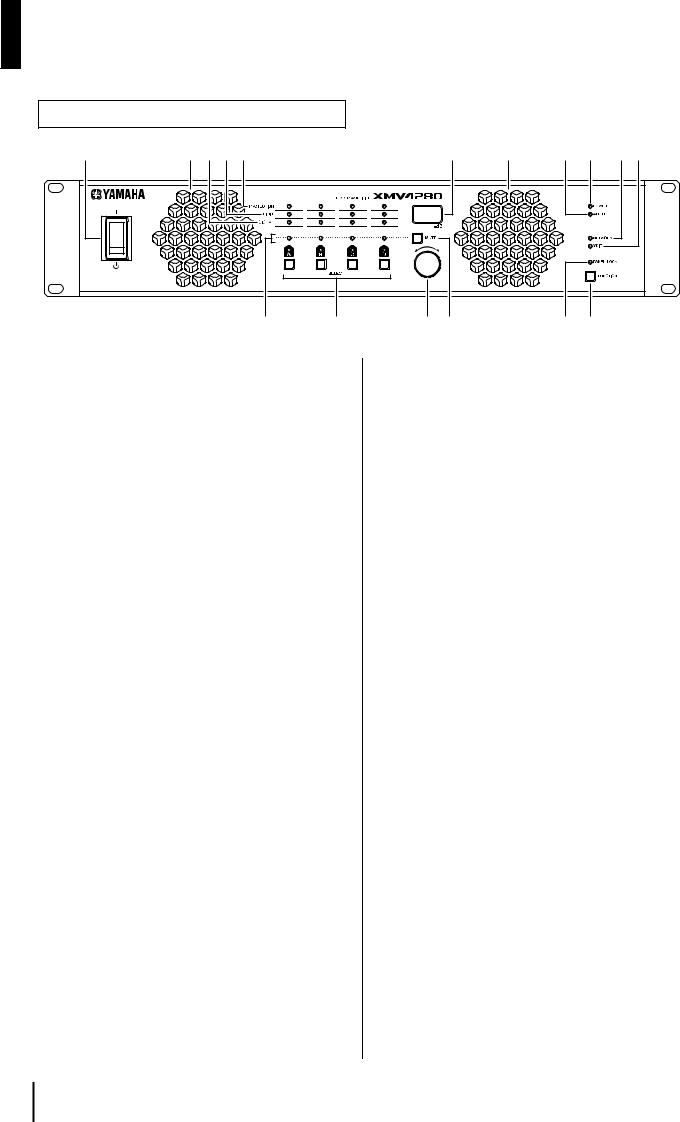
Controls and Functions
Front Panel
q |
!6rew |
y |
!6 |
!1!0!2!3 |
i |
t |
u o |
!4!5 |
qPower Switch
Turns power to the unit ON or OFF. Setting the switch to the upward position turns the power on; the [POWER] indicator will light green. Setting the switch to the downward position turns the power off. If the switch is in the upward position and the [POWER] indicator is blinking, the unit is in standby mode.
 CAUTION
•To ensure that high-volume noise is not output from the speakers, power-on the equipment starting with the audio sources, then the mixer and processors (such as the MTX), and finally the amplifiers. Reverse this order when turning the system off.
•Rapidly turning the power switch ON and OFF in succession can cause the unit to malfunction. After turning the power switch OFF, wait for about 5 seconds before turning it ON again.
•If you modified parameter settings, do not turn the power switch OFF for at least one second. Otherwise, the changes to the settings may be lost.
w[PROTECTION] indicators A/B/C/D
When the protection system is active, the indicator will light orange. If the audio output is muted, turn off the power and wait for the XMV to cool before turning the power on again. The protection circuit will operate in the following situations.
If the amplifier overheats and the output limiter operates
The speaker output will be attenuated if the heat sink of the amplifier section exceeds 80°C (80%), and will be muted if the heat sink exceeds 90°C (90%). The [PROTECTION] indicator will light at 80°C (80%) or higher.
If the power supply overheats and shuts-down
The fan will rotate at high speed if the power supply section exceeds 90°C, and the analog circuits will shut down if it exceeds 100°C.
The [PROTECTION] indicator will light at 100°C or higher.
When overcurrent is detected
If for any reason the impedance falls below rated, the speaker output is muted to prevent overcurrent; muting will be cancelled after approximately one second. If overcurrent is detected after muting is cancelled, the output will be muted again.
If DC output is detected
The power supply section will be shut down.
If excessive total current or maximum current is detected
The output signal will be compressed.
e[LIMIT] indicators A/B/C/D
When the limiter operates, the speaker output will be limited and the indicator will light red. Lower the attenuator value so that the limiter does not operate. The limiter will operate in the following situations.
•When an instantaneous input overload is detected
•When an input overload has been occurring for a specific duration
•When the heat sink of the amplifier section exceeds the allowable temperature
r[SIGNAL] indicators A/B/C/D
The indicator will light when the input from the analog input connector / [YDIF] connector or the output from the [SPEAKERS] connector rises above a certain level.
If the [SIGNAL] indicator is set to show the input from the analog input controller / [YDIF] connector, it will light when the signal level is greater than -40 dBFS.
If it is set to show the output from the [SPEAKERS] connector, the indicator will light when the indicator on the XMV4280 will light when the signal level exceeds 1 Vrms in 280W/8Ω mode. Refer to “[SIGNAL] Indicator Lit Level” in the Specifications for the indicator illumination conditions in each mode.
For details on switching the indicator between input and output, refer to “List of Front Panel Operations” (page 20).
8 XMV4280/XMV4140 Owner’s Manual

t[SELECT] buttons/indicators A/B/C/D
Use these buttons to select the output channel that you want to control. The indicator of the selected channel will light. By using these in conjunction with the [FUNCTION] button, you can change the parameter that is controlled by the encoder. Refer to “List of Front Panel Operations” (page 20). When the [PANEL LOCK] indicator is lit, front panel operations are locked, and output channel operations are not possible. Defeat the lock if you want to perform these operations.
yDisplay
This is a 3-digit 7-segment display that shows information such as the attenuator value of the selected channel.
uEncoder
This encoder is used to edit parameters. For details on the available parameters, refer to “List of Front Panel Operations” (page 20).
When the [PANEL LOCK] indicator is lit, front panel operations are locked, and settings cannot be edited. Defeat the lock if you want to perform these operations.
i[MUTE] indicators A/B/C/D
When you mute an output channel by operating the unit itself or by operations via the [REMOTE] connector or the editor, the indicator of the corresponding channel will light yellow. When the power is turned on, the output signal will also be muted and the indicator will blink yellow until audio starts to be output.
NOTE
Even if muting is off, this indicator will blink when the protection circuit has operated to mute the output.
o[MUTE] button
By holding down the [MUTE] button and pressing the [SELECT] button, you can switch muting on/off for the channel selected by the [SELECT] button. When muting turns on, the [MUTE] indicator will light.
When the [PANEL LOCK] indicator is lit, front panel operations are locked, and channel mute operations are not possible. Defeat the lock if you want to perform these operations.
!0[POWER] indicator
This will light when the power supply is turned on by the power switch (q).
It will blink when the unit is switched to standby mode via the [REMOTE] connector or the editor.
!1[ALERT] indicator
This will blink or light when an abnormality occurs in the unit.
If this is blinking, note the indication in the display and refer to “Alert Numbers and Content” (page 24).
If it is lit, stop operating the unit. After a time, the indicator will change to blinking, and an alert number will appear in the display.
!2[NETWORK] indicator
This will light green if the XMV is in a linked state with an external device via the NETWORK connector. It will blink while data is being communicated.
Controls and Functions
!3[YDIF] indicator
This will light green when the [YDIF] connector is connected normally and a valid word clock is being input.
!4[PANEL LOCK] indicator
Indicator |
Status |
Lit |
Front panel operations are locked. |
Unlit |
Front panel operations are not locked. |
|
Lock is temporarily defeated. When the |
Blinking |
XMV is restarted, it will be in a locked |
|
state, and the indicator will light. |
NOTE
Lock will be temporarily defeated if you press the [FUNCTION] button and the [SELECT] A button.
!5[FUNCTION] button
Use this to check or change the operating mode of the XMV’s front panel. For details on how to perform front panel operations, refer to “List of Front Panel Operations” (page 20).
!6Cooling vent
Located behind the vent is a variable speed cooling fan that draws air in from the front and exhausts it through the rear. The fan speed will automatically vary according to the temperature.
Please be sure that you do not block the air intakes or exhaust vents. You should also clean the air intakes and exhaust vents regularly. If the air intakes are clogged with dust or debris, the amplifier will overheat, which may result in the amplifier shutting down.
XMV4280/XMV4140 Owner’s Manual 9

Controls and Functions
Rear Panel
!7!8 |
|
|
|
|
|
|
!9 |
@2 |
@4@5 |
@6 |
|
|
|
|
|
|
|
|
ON |
|
|
ON |
|
|
|
|
|
|
|
|
|
|
1 |
2 |
3 |
4 |
5 |
6 |
7 |
8 |
|
|
|
@0 @1
!7NETWORK connector
This is a 100BASE-TX Ethernet connector that allows the unit to be connected to a computer via an Ethernet cable.
NOTE
•Use a CAT5e or better STP (Shielded Twisted Pair) cable for the NETWORK connection to prevent electromagnetic interference.
•When using MTX Editor to control the XMV, you must connect the MTX.
!8[YDIF] connectors
These are RJ-45 connectors that allow the unit to be connected via an Ethernet cable to another YDIF-equipped device so that audio signals and word clock signals can be transmitted and received. Use these to link other devices equipped with a [YDIF] connector. For details on settings for receiving audio signals via the [YDIF] connector, refer to “List of Front Panel Operations” (page 20).
Cables used for this connection should be 30 meters or less between devices.
For information on connections that use [YDIF] connectors, refer to the “MTX Setup Manual.”
NOTE
To prevent electromagnetic interference, make connections to the [YDIF] connector using a CAT5e or better STP (Shielded Twisted Pair) cable in which all pins are connected with a straight connection.
!9[UNIT ID] rotary switch
If multiple devices such as XMVs or MTXs are connected on the same network, this rotary switch enables you to specify the UNIT ID that identifies each XMV unit individually.
NOTE
•Do not use “00” as the UNIT ID.
•After you set the [UNIT ID] rotary switch, turn the power to the unit off and then on.
@0Device setup DIP switch
This DIP switch is used to make settings for the XMV. Refer to the following for details on the settings.
NOTE
To change the switch settings, turn off the power to the unit. If you change the settings while the power is on, the change will not be effective until you turn the unit off and then on.
@3
1 |
2 |
3 |
4 |
5 |
6 |
7 |
8 |
Switch 1, 2, 3 (UNIT ID)
Use these DIP switches to specify the upper digit, and use the [UNIT ID] rotary switch to specify the lower digit to set a maximum of 127 combinations of UNIT ID in the range of 01 through 7F (127).
DIP Switches |
Setting |
Description |
|
The UNIT ID’s |
The setting range of the |
|
upper digit is |
[UNIT ID] rotary switch is |
|
set to 0. |
from 01 through 0F. |
|
|
|
|
The UNIT ID’s |
The setting range of the |
|
upper digit is |
[UNIT ID] rotary switch is |
|
set to 1. |
from 10 through 1F. |
|
|
|
|
The UNIT ID’s |
The setting range of the |
|
upper digit is |
[UNIT ID] rotary switch is |
|
set to 2. |
from 20 through 2F. |
|
|
|
|
The UNIT ID’s |
The setting range of the |
|
upper digit is |
[UNIT ID] rotary switch is |
|
set to 3. |
from 30 through 3F. |
|
The UNIT ID’s |
The setting range of the |
|
upper digit is |
[UNIT ID] rotary switch is |
|
set to 4. |
from 40 through 4F. |
|
The UNIT ID’s |
The setting range of the |
|
upper digit is |
[UNIT ID] rotary switch is |
|
set to 5. |
from 50 through 5F. |
|
The UNIT ID’s |
The setting range of the |
|
upper digit is |
[UNIT ID] rotary switch is |
|
set to 6. |
from 60 through 6F. |
|
|
|
|
The UNIT ID’s |
The setting range of the |
|
upper digit is |
[UNIT ID] rotary switch is |
|
set to 7. |
from 70 through 7F. |
|
|
|
10 XMV4280/XMV4140 Owner’s Manual
Switch 4 (LED DIMMER)
This specifies the brightness of the front panel indicators and display.
DIP Switches |
Setting |
Description |
|
|
|
|
OFF |
Normal brightness. |
|
|
|
|
|
Reduced brightness. Use |
|
ON |
this setting if the indicators |
|
and the display are too |
|
|
|
|
|
|
bright. |
|
|
|
NOTE
The brightness of the [POWER] indicator will not be reduced.
Switch 5 (PANEL LOCK)
This specifies the front panel lock setting (locks all panel operations including the [MUTE] button and attenuation adjustments). By selecting the LOCK setting after you’ve completed all settings, you can prevent the volume or mute settings from being inadvertently changed.
Even if the LOCK setting is selected, you can temporarily unlock the panel by pressing the [FUNCTION] button and the [SELECT] A button. The panel will be re-locked when one minute has passed without any operation being performed, or when you once again press the [FUNCTION] button and the [SELECT] A button, or when you turn off the power.
DIP Switches Setting |
Description |
UNLOCK
The front panel will not be locked.
Front panel operations LOCK other than the power will be
locked.
Switch 6 (IP SETTING)
This selects whether the UNIT ID value will be used as the IP address for the unit to communicate with a computer, or whether the IP address will be assigned by the editor or the DHCP server.
DIP Switches Setting |
Description |
The IP address will be specified using the UNIT ID
UNIT ID
value.
The IP address will be 192.168.0.xxx (xxx is the UNIT ID value).
The IP address will be PC specified by the editor or
the DHCP server.
Switches 7 and 8 (START UP MODE)
These specify the startup mode of the XMV.
DIP Switches Setting |
Description |
RESUME
The unit will start up normally.
The internal memory will be initialized. For details on the
INITIALIZE memory that will be initialized, refer to “Initializing the Internal Memory” (page 22).
Controls and Functions
@1Analog input connectors
These are Euroblock 3-pin analog audio input connectors. For details on settings for receiving audio signals via the analog input connectors, refer to “List of Front Panel Operations” (page 20).
For details on how to attach Euroblock connectors, refer to the “Setup” section entitled “Connecting the analog inputs (Euroblock)” (page 13).
@2[SPEAKERS] DIP switch
This DIP switch makes settings for the XMV’s amplifier in groups of two channels.
Switches 1 through 4 specify the output setting for channels C/D, and switches 5 through 8 specify the output setting for channels A/B.
Use these switches to make the following settings.
|
|
Switches 1–4 |
|
Description |
(channels C/D) |
||
Switches 5–8 |
|||
|
|
||
|
|
(channels A/B) |
|
|
|
|
|
|
280W{140W}, 8Ω |
|
|
|
|
|
|
Low-impedance |
560W{280W}*, 8Ω |
|
|
Connection |
280W{140W}, 4Ω |
|
|
|
|
|
|
|
560W{280W}*, 4Ω |
|
|
|
|
|
|
High-impedance |
70V, 250W{125W} |
|
|
Connection |
100V, 250W{125W} |
|
|
|
|
|
|
*If this setting is chosen, input/output will be disabled for channels B and D.
Low impedance connection / high impedance connection (switches 1 and 5)
These select either a low impedance connection or a high impedance connection. Set them as appropriate for the connected speakers and the way in which the speakers are connected. For details on connections, refer to “Highimpedance and Low-impedance Connections” (page 25).
Impedance (switches 3 and 7)
When using a low impedance connection, set these as appropriate for the impedance of the speakers that are connected. Check the specifications of the speakers.
For example if two 8Ω speakers are connected in parallel, the total impedance will be 4Ω.
Double Power mode (switches 4 and 8)
When a low impedance connection is used, these switches specify the output of the amplifier. If the 280W {140W} setting is selected, input/output is enabled for both channels. If the 560W {280W} setting is selected, the output from the amplifier will be doubled, but input/ output will be disabled for channels B and D.
70V/100V (switches 2 and 6)
When a high impedance connection is used, these switches specify the maximum output voltage (Vrms) of the amplifier.
XMV4280/XMV4140 Owner’s Manual 11

Controls and Functions
@3[SPEAKERS] output connectors
These are barrier strip type speaker output connectors. For details on how to make connections to a barrier strip, refer to the “Setup” section entitled “Connecting the speaker output connectors” (page 15).
@4[REMOTE] connector
This is a Euroblock 3-pin connector that allows muting/ unmuting of all channels and power-on/standby to be controlled remotely. For details, refer to “Using and connecting the [REMOTE] connector and [FAULT OUTPUT] connector” (page 18).
@5[FAULT OUTPUT] connector
This is a Euroblock 3-pin connector that allows an external device to be controlled when a fatal malfunction occurs in this unit. NC and C will be shorted when the amplifier is operating normally; NO and C will be shorted when a problem occurs (page 18).
If a problem occurs, the [PROTECTION] indicator will light.
@6[AC IN] socket
Connect the supplied AC power cord here. First connect the AC power cord to the socket on the rear panel of this unit, then plug it into an appropriate AC power outlet.
 CAUTION
Before connecting or disconnecting the power cord, make sure that the power to the unit is turned OFF.
12 XMV4280/XMV4140 Owner’s Manual
Loading...