


2008
OWNER’S SERVICE MANUAL
WR450F(X)
5TJ-28199-71

WR450F (X)
OWNER'S SERVICE MANUAL ©2007 by Yamaha Motor Co., Ltd. 1st Edition, June 2007
All rights reserved. Any reprinting or unauthorized use without the written permission of Yamaha Motor Co., Ltd. is expressly prohibited.
Printed in Japan

FOREWORD
INTRODUCTION
Congratulations on your purchase of a Yamaha WR series. This model is the culmination of Yamaha's vast experience in the production of pacesetting racing machines. It represents the highest grade of craftsmanship and reliability that have made Yamaha a leader.
This manual explains operation, inspection, basic maintenance and tuning of your machine. If you have any questions about this manual or your machine, please contact your Yamaha dealer.
Yamaha continually seeks advancements in product design and quality. Therefore, while this manual contains the most current product information available at the time of printing, there may be minor discrepancies between your machine and this manual. If you have any questions concerning this manual, please consult your Yamaha dealer.
PLEASE READ THIS MANUAL CAREFULLY AND COMPLETELY BEFORE OPERATING THIS MACHINE. DO NOT ATTEMPT TO OPERATE THIS MACHINE UNTIL YOU HAVE ATTAINED A SATISFACTORY KNOWLEDGE OF ITS CONTROLS AND OPERATING FEATURES AND UNTIL YOU HAVE BEEN TRAINED IN SAFE AND PROPER RIDING TECHNIQUES. REGULAR INSPECTIONS AND CAREFUL MAINTENANCE, ALONG WITH GOOD RIDING SKILLS, WILL ENSURE THAT YOU SAFETY ENJOY THE CAPABILITIES AND THE RELIABILITY OF THIS MACHINE.
PARTICULARLY IMPORTANT INFORMATION
The Safety Alert Symbol means ATTENTION! BECOME ALERT! YOUR SAFETY IS INVOLVED!
Failure to follow WARNING instructions could result in severe injury or death to the machine operator, a bystander, or a person inspecting or repairing the machine.
A CAUTION indicates special precautions that must be taken to avoid damage to the machine.
A NOTE provides key information to make procedures easier or clearer.
IMPORTANT NOTICE
THIS MACHINE IS DESIGNED STRICTLY FOR COMPETITION USE, ONLY ON A CLOSED COURSE. It is illegal for this machine to be operated on any public street, road, or highway. Off-road use on public lands may be illegal. Please check local regulations before riding.
1.THIS MACHINE IS TO BE OPERATED BY AN EXPERIENCED RIDER ONLY.
Do not attempt to operate this machine at maximum power until you are totally familiar with its characteristics.
2.THIS MACHINE IS DESIGNED TO BE RIDDEN BY THE OPERATOR ONLY.
Do not carry passengers on this machine.
3.ALWAYS WEAR PROTECTIVE APPAREL.
When operating this machine, always wear an approved helmet with goggles or a face shield. Also wear heavy boots, gloves, and protective clothing. Always wear proper fitting clothing that will not be caught in any of the moving parts or controls of the machine.
4.ALWAYS MAINTAIN YOUR MACHINE IN PROPER WORKING ORDER.
For safety and reliability, the machine must be properly maintained. Always perform the pre-operation checks indicated in this manual. Correcting a mechanical problem before you ride may prevent an accident.
5.GASOLINE IS HIGHLY FLAMMABLE.
Always turn off the engine while refueling. Take care to not spill any gasoline on the engine or exhaust system. Never refuel in the vicinity of an open flame, or while smoking.
6.GASOLINE CAN CAUSE INJURY.
If you should swallow some gasoline, inhale excess gasoline vapors, or allow any gasoline to get into your eyes, contact a doctor immediately. If any gasoline spills onto your skin or clothing, immediately wash skin areas with soap and water, and change your clothes.
7.ONLY OPERATE THE MACHINE IN AN AREA WITH ADEQUATE VENTILATION. Never start the engine or let it run for any length of time in an enclosed area. Exhaust fumes are poisonous. These fumes contain carbon monoxide, which by itself is odorless and colorless. Carbon monoxide is a dangerous gas which can cause unconsciousness or can be lethal.
8.PARK THE MACHINE CAREFULLY; TURN OFF THE ENGINE.
Always turn off the engine if you are going to leave the machine. Do not park the machine on a slope or soft ground as it may fall over.
9.THE ENGINE, EXHAUST PIPE, MUFFLER, AND OIL TANK WILL BE VERY HOT AFTER THE ENGINE HAS BEEN RUN.
Be careful not to touch them or to allow any clothing item to contact them during inspection or repair.

10.PROPERLY SECURE THE MACHINE BEFORE TRANSPORTING IT.
When transporting the machine in another vehicle, always be sure it is properly secured and in an upright position and that the fuel cock is in the "OFF" position. Otherwise, fuel may leak out of the carburetor or fuel tank.
TO THE NEW OWNER
This manual will provide you with a good basic understanding of features, operation, and basic maintenance and inspection items of this machine. Please read this manual carefully and completely before operating your new machine. If you have any questions regarding the operation or maintenance of your machine, please consult your Yamaha dealer.
This manual should be considered a permanent part of this machine and should remain with it even if the machine is subsequently sold.
NOTICE
Some data in this manual may become outdated due to improvements made to this model in the future. If there is any question you have regarding this manual or your machine, please consult your Yamaha dealer.
F.I.M. MACHINE WEIGHTS
Weights of machines without fuel
The minimum weights for motocross machines are:
for the class 125 cc: minimum 88 kg (194 lb)
for the class 250 cc: minimum 98 kg (216 lb)
for the class 500 cc: minimum 102 kg (225 lb)
In modifying your machine (e.g., for weight reduction), take note of the above limits of weight.
HOW TO USE THIS MANUAL
FINDING THE REQUIRED PAGE
1.This manual consists of seven chapters; "General Information", "Specifications", "Regular inspection and adjustments", "Tuning", "Engine", "Chassis" and "Electrical".
2.The table of contents is at the beginning of the manual. Look over the general layout of the book before finding then required chapter and item.
Bend the book at its edge, as shown, to find the required fore edge symbol mark and go to a page for required item and description.
MANUAL FORMAT
All of the procedures in this manual are organized in a sequential, step- by-step format. The information has been complied to provide the mechanic with an easy to read, handy reference that contains comprehensive explanations of all disassembly, repair, assembly, and inspection operations.
In this revised format, the condition of a faulty component will precede an arrow symbol and the course of action required will follow the symbol, e.g.,
•Bearings
Pitting/damage → Replace.

HOW TO READ DESCRIPTIONS
To help identify parts and clarify procedure steps, there are exploded diagrams at the start of each removal and disassembly section.
1.An easy-to-see exploded diagram "1" is provided for removal and disassembly jobs.
2.Numbers "2" are given in the or-
der of the jobs in the exploded diagram. A number that is enclosed by a circle indicates a disassembly step.
3.An explanation of jobs and notes is presented in an easy-to-read way by the use of symbol marks "3". The meanings of the symbol marks are given on the next page.
4.A job instruction chart "4" accompanies the exploded diagram, providing the order of jobs, names of parts, notes in jobs, etc.
5.For jobs requiring more information, the step-by-step format supplements "5" are given in addition to the exploded diagram and job instruction chart.
3 |
5 |
1
2
4
ILLUSTRATED SYMBOLS (Refer to the illustration)
Illustrated symbols "1" to "7" are used to identify the specifications appearing in the text.
1.With engine mounted
2.Filling fluid
3.Lubricant
4.Special tool
5.Tightening
6.Specified value, Service limit
7.Resistance (Ω), Voltage (V), Electric current (A)
Illustrated symbols "8" to "13" in the exploded diagrams indicate grade of lubricant and location of lubrication point.
8.Apply engine oil
9.Apply molybdenum disulfide oil
10.Apply brake fluid
11.Apply lightweight lithium-soap base grease
12.Apply molybdenum disulfide grease
13.Apply silicone grease Illustrated symbols "14" to "15" in the exploded diagrams indicate where to apply a locking agent and where to install new parts.
14.Apply locking agent (LOCTITE®)
15.Use new one

TABLE OF CONTENTS
GENERAL INFORMATION |
1 |
|
|
|
|
|
|
|
SPECIFICATIONS |
2 |
|
|
|
|
|
|
|
REGULAR INSPECTION AND |
3 |
|
ADJUSTMENTS |
||
|
||
|
|
|
|
|
|
TUNING |
4 |
|
|
|
|
|
|
|
ENGINE |
5 |
|
|
|
|
|
|
|
CHASSIS |
6 |
|
|
|
|
|
|
|
ELECTRICAL |
7 |
|
|
|

CHAPTER 1
GENERAL INFOR-
MATION
DESCRIPTION ................. |
1-1 |
MACHINE |
|
IDENTIFICATION ............. |
1-2 |
INCLUDED PARTS .......... |
1-2 |
IMPORTANT |
|
INFORMATION................. |
1-2 |
CHECKING OF |
|
CONNECTION.................. |
1-3 |
SPECIAL TOOLS ............. |
1-4 |
CONTROL FUNCTIONS .. |
1-8 |
MULTI-FUNCTION |
|
DISPLAY .......................... |
1-9 |
STARTING AND |
|
BREAK-IN ...................... |
1-14 |
TORQUE-CHECK |
|
POINTS........................... |
1-16 |
CLEANING AND |
|
STORAGE ...................... |
1-17 |
CHAPTER 2
SPECIFICATIONS
GENERAL |
|
SPECIFICATIONS |
............ 2-1 |
MAINTENANCE |
|
SPECIFICATIONS............ |
2-3 |
TIGHTENING |
|
TORQUES ...................... |
2-12 |
LUBRICATION |
|
DIAGRAMS .................... |
2-19 |
CABLE ROUTING |
|
DIAGRAM....................... |
2-21 |
CONTENTS
CHAPTER 3
REGULAR INSPEC-
TION AND AD-
JUSTMENTS
MAINTENANCE |
|
INTERVALS...................... |
3-1 |
PRE-OPERATION |
|
INSPECTION AND |
|
MAINTENANCE................ |
3-5 |
ENGINE ............................ |
3-6 |
CHASSIS ........................ |
3-17 |
ELECTRICAL ................. |
3-27 |
CHAPTER 4
TUNING
ENGINE ............................ |
4-1 |
CHASSIS .......................... |
4-5 |
CHAPTER 5
ENGINE
RADIATOR ....................... |
5-1 |
CARBURETOR................. |
5-4 |
AIR INDICTOIN |
|
SYSTEM ......................... |
5-11 |
CAMSHAFTS.................. |
5-13 |
CYLINDER HEAD........... |
5-18 |
VALVES AND |
|
VALVE SPRINGS ........... |
5-21 |
CYLINDER AND |
|
PISTON........................... |
5-25 |
CLUTCH ......................... |
5-28 |
OIL FILTER ELEMENT |
|
AND WATER PUMP....... |
5-32 |
BALANCER .................... |
5-36 |
OIL PUMP....................... |
5-38 |
KICK SHAFT AND |
|
SHIFT SHAFT................. |
5-41 |
AC MAGNETO AND |
|
STARTER CLUTCH ....... |
5-46 |
ENGINE REMOVAL ....... |
5-51 |
CRANKCASE AND |
|
CRANKSHAFT ............... |
5-55 |
TRANSMISSION, SHIFT |
|
CAM AND |
|
SHIFT FORK................... |
5-61 |
CHAPTER 6
CHASSIS
FRONT WHEEL AND |
|
REAR WHEEL .................. |
6-1 |
FRONT BRAKE AND |
|
REAR BRAKE .................. |
6-6 |
FRONT FORK................. |
6-16 |
HANDLEBAR.................. |
6-23 |
STEERING ...................... |
6-27 |
SWINGARM .................... |
6-31 |
REAR SHOCK |
|
ABSORBER.................... |
6-36 |
CHAPTER 7
ELECTRICAL
ELECTRICAL |
|
COMPONENTS AND |
|
WIRING DIAGRAM........... |
7-1 |
IGNITION SYSTEM........... |
7-3 |
ELECTRIC STARTING |
|
SYSTEM............................ |
7-5 |
CHARGING SYSTEM ..... |
7-13 |
THROTTLE POSITION |
|
SENSOR SYSTEM ......... |
7-15 |
LIGHTING SYSTEM ....... |
7-18 |
SIGNALING SYSTEM..... |
7-20 |

DESCRIPTION
GENERAL INFORMATION
DESCRIPTION
1 |
1. |
Clutch lever |
14. |
Headlight |
2. |
Hot starter lever |
15. |
Radiator |
3. |
Engine stop switch |
16. |
Coolant drain bolt |
4. |
Multi-function display |
17. |
Rear brake pedal |
5. |
Main switch |
18. |
Valve joint |
6. |
Start switch |
19. |
Fuel cock |
7. |
Front brake lever |
20. |
Cold starter knob |
8. |
Throttle grip |
21. |
Air cleaner |
9. |
Radiator cap |
22. |
Catch tank |
10. |
Fuel tank cap |
23. |
Drive chain |
11. |
Taillight |
24. |
Shift pedal |
12. |
Kickstarter crank |
25. |
Oil dipstick |
13. |
Fuel tank |
26. |
Front fork |
•The machine you have purchased may differ slightly from those shown in the following.
•Designs and specifications are subject to change without notice.
1-1

MACHINE IDENTIFICATION
MACHINE IDENTIFICATION
There are two significant reasons for knowing the serial number of your machine:
1.When ordering parts, you can give the number to your Yamaha dealer for positive identification of the model you own.
2.If your machine is stolen, the authorities will need the number to search for and identify your machine.
VEHICLE IDENTIFICATION NUMBER
The vehicle identification number "1" is stamped on the right of the steering head pipe.
SPARK PLUG WRENCH
This spark plug wrench "1" is used to remove and install the spark plug.
NIPPLE WRENCH
This nipple wrench "1" is used to tighten the spoke.
2.Use proper tools and cleaning equipment. Refer to "SPECIAL TOOLS" section.
ENGINE SERIAL NUMBER
The engine serial number "1" is stamped into the elevated part of the right-side of the engine.
MODEL LABEL
The model label "1" is affixed to the frame under the rider's seat. This information will be needed to order spare parts.
INCLUDED PARTS
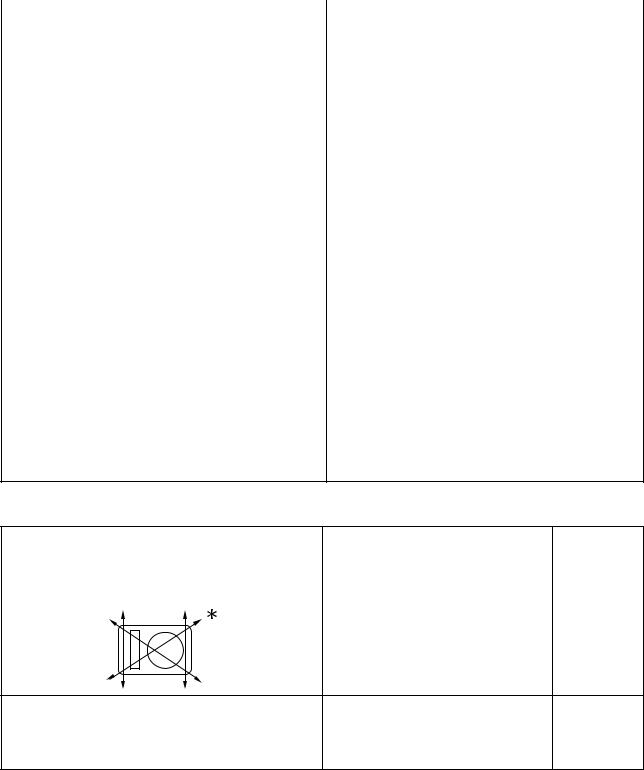
VALVE JOINT
This valve joint "1" prevents fuel from flowing out and is installed to the fuel tank breather hose.
In this installation, make sure the arrow faces the fuel tank and also downward.
JET NEEDLE PULL-UP TOOL
The jet needle pull-up tool "1" is used to pull the jet needle out of the carburetor.
3.When disassembling the machine, keep mated parts together. They include gears, cylinders, pistons, and other mated parts that have been "mated" through normal wear. Mated parts must be reused as an assembly or replaced.
IMPORTANT INFORMATION
PREPARATION FOR REMOVAL AND DISASSEMBLY
1.Remove all dirt, mud, dust, and foreign material before removal and disassembly.
•When washing the machine with high pressured water, cover the parts follows.
Silencer exhaust port Side cover air intake port
Water pump housing hole at the bottom
Drain hole on the cylinder head (right side)
All electrical components
4.During the machine disassembly, clean all parts and place them in trays in the order of disassembly. This will speed up assembly time and help assure that all parts are correctly reinstalled.
5. Keep away from fire.
1-2
CHECKING OF CONNECTION
ALL REPLACEMENT PARTS
1.We recommend to use Yamaha genuine parts for all replacements. Use oil and/or grease recommended by Yamaha for assembly and adjustment.
GASKETS, OIL SEALS AND O- RINGS
1.All gaskets, oil seals, and O-rings should be replaced when an engine is overhauled. All gasket surfaces, oil seal lips, and O-rings must be cleaned.
2.Properly oil all mating parts and bearings during reassembly. Apply grease to the oil seal lips.
LOCK WASHERS/PLATES AND COTTER PINS
1.All lock washers/plates "1" and cotter pins must be replaced when they are removed. Lock tab(s) should be bent along the bolt or nut flat(s) after the bolt or nut has been properly tightened.
CIRCLIPS
1.All circlips should be inspected carefully before reassembly. Always replace piston pin clips after one use. Replace distorted circlips. When installing a circlip "1", make sure that the sharp-edged corner "2" is positioned opposite to the thrust "3" it receives. See the sectional view.
BEARINGS AND OIL SEALS
1.Install the bearing(s) "1" and oil seal(s) "2" with their manufacturer's marks or numbers facing outward. (In other words, the stamped letters must be on the side exposed to view.) When installing oil seal(s), apply a light coating of lightweight lithium base grease to the seal lip(s). Oil the bearings liberally when installing.
Do not use compressed air to spin the bearings dry. This causes damage to the bearing surfaces.
CHECKING OF
CONNECTION
Dealing with stains, rust, moisture, etc. on the connector.
1.Disconnect:
•Connector
2.Dry each terminal with an air blower.
3.Connect and disconnect the connector two or three times.
4.Pull the lead to check that it will not come off.
5.If the terminal comes off, bend up the pin "1" and reinsert the terminal into the connector.
6.Connect:
•Connector
The two connectors "click" together.
7. Check for continuity with a tester.
•If there in no continuity, clean the terminals.
•Be sure to perform the steps 1 to 7 listed above when checking the wire harness.
•For a field remedy, use a contact revitalizer available on the market.
•Use the tester on the connector as shown.
1-3

SPECIAL TOOLS
SPECIAL TOOLS
The proper special tools are necessary for complete and accurate tune-up and assembly. Using the correct special tool will help prevent damage caused by the use of improper tools or improvised techniques. The shape and part number used for the special tool differ by country, so two types are provided. Refer to the list provided to avoid errors when placing an order.
•For U.S.A. and Canada, use part number starting with "YM-", "YU-" or "ACC-".
•For others, use part number starting with "90890-".
Tool name/Part number |
How to use |
Illustration |
|
|
|
Dial gauge and stand |
These tools are used to check each |
|
YU-3097, 90890-01252 |
part for runout or bent. |
|
Stand |
|
|
YU-1256 |
|
|
|
|
|
Crankshaft installing tool |
These tools are used to install the |
|
Crankshaft installing pot |
crankshaft. |
|
YU-90050, 90890-01274 |
|
|
Crankshaft installing bolt |
|
|
YU-90050, 90890-01275 |
|
|
Spacer (crankshaft installer) |
|
|
YM-91044, 90890-04081 |
|
|
Adapter (M12) |
|
|
YU-90063, 90890-01278 |
|
|
|
|
|
Piston pin puller set |
This tool is used to remove the pis- |
|
YU-1304, 90890-01304 |
ton pin. |
|
|
|
|
Radiator cap tester |
These tools are used for checking |
|
YU-24460-01, 90890-01325 |
the cooling system. |
|
Radiator cap tester adapter |
|
|
YU-33984, 90890-01352 |
|
|
|
|
|
Steering nut wrench |
This tool is used when tighten the |
|
YU-33975, 90890-01403 |
steering ring nut to specification. |
|
|
|
|
1-4

|
|
SPECIAL TOOLS |
|
|
|
|
|
|
Tool name/Part number |
How to use |
Illustration |
|
|
|
Damper rod holder |
Use this tool to remove and install |
|
YM-01494, 90890-01494 |
the damper rod. |
|
|
|
|
Fork seal driver |
This tool is used when install the fork |
|
YM-A0948, 90890-01502 |
oil seal. |
|
|
|
|
Sheave holder |
This tool is used for when loosening |
|
YS-1880-A, 90890-01701 |
or tightening the flywheel magneto |
|
|
securing nut. |
|
|
|
|
Pocket tester |
Use this tool to inspect the coil resis- |
|
YU-3112-C, 90890-03112 |
tance, output voltage and amper- |
|
|
age. |
|
|
|
|
Timing light |
This tool is necessary for checking |
|
YM-33277-A, 90890-03141 |
ignition timing. |
|
|
|
|
Valve spring compressor |
This tool is needed to remove and |
|
YM-4019, 90890-04019 |
install the valve assemblies. |
|
|
|
|
1-5

|
|
SPECIAL TOOLS |
|
|
|
|
|
|
Tool name/Part number |
How to use |
Illustration |
|
|
|
Clutch holding tool |
This tool is used to hold the clutch |
|
YM-91042, 90890-04086 |
when removing or installing the |
|
|
clutch boss securing nut. |
|
|
|
|
Valve guide remover |
This tool is needed to remove and |
|
Intake 4.5 mm (0.18 in) |
install the valve guide. |
|
Exhaust 5.0 mm (0.20 in) |
|
|
YM-4116, 90890-04116 |
|
|
YM-4097, 90890-04097 |
|
|
|
|
|
Valve guide installer |
This tool is needed to install the |
|
Intake 4.5 mm (0.18 in) |
valve guide. |
|
Exhaust 5.0 mm (0.20 in) |
|
|
YM-4117, 90890-04117 |
|
|
YM-4098, 90890-04098 |
|
|
|
|
|
Valve guide reamer |
This tool is needed to rebore the |
|
Intake 4.5 mm (0.18 in) |
new valve guide. |
|
Exhaust 5.0 mm (0.20 in) |
|
|
YM-4118, 90890-04118 |
|
|
YM-4099, 90890-04099 |
|
|
|
|
|
Rotor puller |
This tool is used to remove the fly- |
|
YM-4142, 90890-04142 |
wheel magneto. |
|
|
|
|
Crankcase separating tool |
These tool is used to remove the |
|
YU-A9642 |
crankshaft from either case. |
|
90890-04152 |
|
|
|
|
|
1-6

|
|
SPECIAL TOOLS |
|
|
|
|
|
|
Tool name/Part number |
How to use |
Illustration |
|
|
|
Dynamic spark tester |
This instrument is necessary for |
|
YM-34487 |
checking the ignition system compo- |
|
Ignition checker |
nents. |
|
90890-06754 |
|
|
|
|
|
Vacuum/pressure pump gauge set |
This tool is used to check the air in- |
|
YB-35956-A, 90890-06756 |
duction system. |
|
|
|
|
Digital tachometer |
This tool is needed for observing en- |
|
YU-39951-B, 90890-06760 |
gine rpm. |
|
|
|
|
YAMAHA Bond No. 1215 (ThreeB- |
This sealant (Bond) is used for |
|
ond® No. 1215) |
crankcase mating surface, etc. |
|
90890-85505 |
|
|
|
|
|
1-7
CONTROL FUNCTIONS
CONTROL FUNCTIONS
MAIN SWITCH
Functions of the respective switch positions are as follows:
ON:
The engine can be started only at this position.
OFF:
All electrical circuits are switched off.
Main switch indicator light
The main switch "1" is equipped with an indicator light "2" to avoid forgetting to turn it off. This light functions as follows.
•It lights up with the main switch "ON".
•It goes out when the engine increases its speed after being started.
•It lights up again when the engine is stopped.
If the indicator light will not light up with the main switch "ON", it shows a lack of the battery voltage. Recharge the battery.
ENGINE STOP SWITCH
The engine stop switch "1" is located on the left handlebar. Continue pushing the engine stop switch till the engine comes to a stop.
START SWITCH
The start switch "1" is located on the right handlebar. Push this switch to crank the engine with the starter.
CLUTCH LEVER
The clutch lever "1" is located on the left handlebar; it disengages or engages the clutch. Pull the clutch lever to the handlebar to disengage the clutch, and release the lever to engage the clutch. The lever should be pulled rapidly and released slowly for smooth starts.
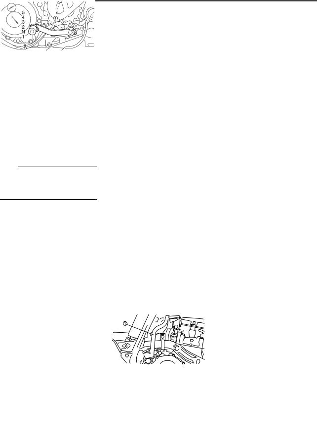
SHIFT PEDAL
The gear ratios of the constant-mesh 5 speed transmission are ideally spaced. The gears can be shifted by using the shift pedal "1" on the left side of the engine.
KICKSTARTER CRANK
Rotate the kickstarter crank "1" away from the engine. Push the starter down lightly with your foot until the gears engage, then kick smoothly and forcefully to start the engine. This model has a primary kickstarter crank so the engine can be started in any gear if the clutch is disengaged. In normal practices, however, shift to neutral before starting.
THROTTLE GRIP
The throttle grip "1" is located on the right handlebar; it accelerates or decelerates the engine. For acceleration, turn the grip toward you; for deceleration, turn it away from you.
FRONT BRAKE LEVER
The front brake lever "1" is located on the right handlebar. Pull it toward the handlebar to activate the front brake.
REAR BRAKE PEDAL
The rear brake pedal "1" is located on the right side of the machine. Press down on the brake pedal to activate the rear brake.
FUEL COCK
The fuel cock supplies fuel from the tank to carburetor and also filters the fuel. The fuel cock has the three positions:
OFF:
With the lever in this position, fuel will not flow. Always return the lever to this position when the engine is not running.
ON:
With the lever in this position, fuel flows to the carburetor. Normal riding is done with the lever in this position. RES:
With the lever in this position fuel flows to the carburetor from the reserve section of the fuel tank after the main supply of the fuel has been depleted. Normal riding is possible with the lever is in this position, but it is recommended to add fuel as soon as possible.
1-8
MULTI-FUNCTION DISPLAY
COLD STARTER KNOB
When cold, the engine requires a richer air-fuel mixture for starting. A separate starter circuit, which is controlled by the cold starter knob "1", supplies this mixture. Pull the cold starter knob out to open the circuit for starting. When the engine has warmed up, push it in to close the circuit.
HOT STARTER LEVER
The hot starter lever "1" is used when starting a warm engine. Use the hot starter lever when starting the engine again immediately after it was stopped (the engine is still warm). Pulling the hot starter lever injects secondary air to thin the air-fuel mixture temporarily, allowing the engine to be started more easily.
MULTI-FUNCTION DISPLAY
Be sure to stop the machine before making any setting changes to the multi-function display.
The multi-function display is equipped with the following: BASIC MODE:
•Speedometer
•Clock
•Two tripmeters (which shows the distance that has been traveled since it was last set to zero)
RACE MODE:
•Timer (which shows the time that has been accumulated since the start of timer measurement)
•Tripmeter (which shows the accumulated travel distance in timer measurement)
•Change tripmeter digits (capable of change to any given ones)
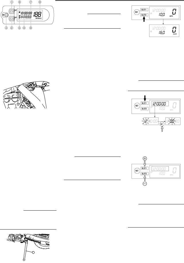
DESCRIPTION
Operation buttons:
1.Select button "SLCT 1"
2.Select button "SLCT 2"
3.Reset button "RST"
Screen display:
4.Tripmeter indicator 
5.Tripmeter indicator 
6.Timer indicator 
7.Clock/Timer
8.Speedometer
9.Odometer/Tripmeter
The operation buttons can be pushed in the following two manners:
Short push: Push the button. ( ) Long push: Push the button for 2 seconds or more. (
 )
)
Setting the time
1.Push the "SLCT1" button for 2 seconds or more to enter the time setting mode.
2.Push the "RST" button to change the display for time indication. The display will change in the fol-
lowing order: Hour→Minute→Second→Hour.
The digits capable of setting go on flashing.
3.Push the "SLCT1" button (plus) or "SLCT2" button (minus) and change the time. A long push on the button will fast-forward the time.
SIDESTAND
This sidestand "1" is used to support only the machine when standing or transporting it.
•Never apply additional force to the sidestand.
•Hold up the sidestand before starting out.
BASIC MODE
Changing speedometer display (for U.K.)
1.Push the "SLCT2" button for 2 seconds or more to change the speedometer units. The speedometer display will change in the
following order:
MPH → km/h → MPH.
4.To end the setting, push the "RST" button for 2 seconds or more.
•In a 30-second absence of button operation, the setting will come to an end with the indicated time.
•To reset the seconds, push the "SLCT1" button or "SLCT2" button.
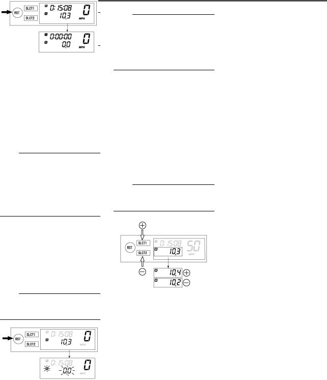
Changing odometer and tripmeter A/B (TRIP A/B)
1.Push the "SLCT2" button to change the tripmeter display. The display will change in the follow-
ing order:
Odometer →TRIP A→TRIP B→ TRIP A → Odometer.
1-9

MULTI-FUNCTION DISPLAY
To reset the digits, select the tripmeter involved and push the "RST" button for 2 seconds or more.
CHANGEOVER TO BASIC MODE/ RACE MODE
•Measurement using the timer function can be made in RACE MODE.
•Indicator  will light up as an identifier that shows RACE MODE has been selected.
•RACE MODE cannot display the functions as in BASIC MODE.
•Changeover to RACE MODE forces the digits for tripmeter A (TRIP A) in BASIC MODE to be reset.
Changeover from BASIC MODE to RACE MODE
1.Push the "SLCT1" button and "SLCT2" button for 2 seconds or more at the same time to change over to RACE MODE.
Changeover to RACE MODE will put manual start measurement on standby causing  and
and  to flash. (For manual start, refer to "Putting measurement on standby" in "RACE MODE".)
Returning to BASIC MODE from RACE MODE
It is possible to return to BASIC MODE with timer measurement at a stop.
1.Check that the timer is not in operation. If the timer is in operation, stop the timer by pushing the "SLCT1" button and "SLCT2" button at the same time.
2.Push the "SLCT1" button and "SLCT2" button for 2 seconds or more at the same time to change over to BASIC MODE.
RACE MODE
Putting measurement on standby
Starting measurement consists of the following two starts, either of which can be selected.
• Manual start
Starting measurement by the rider himself operating the button. (A long push on the "SLCT2" button will put measurement on standby.)
• Auto start
Starting timer measurement automatically on detection of the movement of the machine. (A long push on the "SLCT1" button will put measurement on standby.)
Manual start
Initial setting at changeover to RACE MODE will remain for manual start.
1.Check that changeover to RACE MODE has been made. (Refer to "Changeover from BASIC MODE to RACE MODE".)
When the machine is made ready for a run by manual start,  and
and  will start flashing.
2.Start timer measurement by pushing the "RST" button.
3.When stopping timer measurement, pushing the "SLCT1" button and "SLCT2" button at the same time.
If the machine is run while timer measurement is not made, no change will occur to the digit in tripmeter A (TRIP A).
4. To resume the measurement, again push the "SLCT1" button and "SLCT2" button at the same time.
Auto start
1.Check that changeover has been made to RACE MODE. (Refer to "Changeover from BASIC MODE to RACE MODE".)
2.Make the machine ready for a run by pushing the "SLCT1" button for 2 seconds or more.
When the measurement is made ready for a run by auto start,  and
and  will start flashing. Timer display will turn on scrolling from left to right.
3.Run the machine and start timer measurement.
4.To stop timer measurement, pushing the "SLCT1" button and "SLCT2" button at the same time.
1-10
MULTI-FUNCTION DISPLAY
If the machine is run while timer measurement is not made, no change will occur to the digit in tripmeter A (TRIP A).
5. To resume the measurement, again pushing the "SLCT1" button and "SLCT2" button at the same time.
Resetting measurement data
Resetting can be made in the following two manners.
Resetting is possible while timer measurement is made:
• Reset tripmeter A.
Resetting is possible while timer measurement is not made:
• Reset tripmeter A and timer.
Resetting tripmeter A (TRIP A)
1.Check that the timer is in operation. If the timer is not in operation, start the timer by pushing the "SLCT1" button and "SLCT2" button at the same time.
2.Reset tripmeter A (TRIP A) display by pushing the "RST" button for 2 seconds or more.
If reset,  and travel distance display will go on flashing for four seconds.
Resetting tripmeter A (TRIP A) and timer
1.Check that the timer is not in operation. If the timer is in operation, stop it by pushing the "SLCT1" button and "SLCT2" button at the same time.
2.Reset all measured data by pushing the "RST" button for 2 seconds or more.
•Resetting will reset the timer display and travel distance display and put measurement on standby.
•Auto start attempt will put measurement on standby as such. Likewise, manual start attempt will put measurement on standby as such.
Correcting tripmeter A (TRIP A)
1.Change the travel distance display by pushing the "SLCT1" button (plus) or "SLCT2" button (minus). A long push on the button will fast-forward the change.
Change can be made any time while timer measurement is or is not being made.
1-11
MULTI-FUNCTION DISPLAY
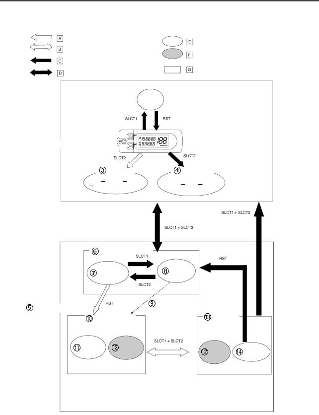
FUNCTION DIAGRAM
A short push on the button changes the operation in the arrowed direction.
A short push on the button changes
the operation in both arrowed directions.
A long push on the button changes the operation in the arrowed direction.
A long push on the button changes the operation in both arrowed directions.
 Clock
Clock
Meter function
Function that can be performed whether the time is or is not in operation.
Extent to which the meter can operate
 BASIC MODE
Tripmeter |
|
|
Speedometer |
|
|
|
(for U.K.) |
ODO TRIP A |
TRIP B |
MPH |
km/h MPH |
ODO |
|
||
|
|
|
Putting measurement on standby
|
Manual start |
Auto start |
|
|
|
|
|
||
|
|
Measurement starts as the |
|
|
RACE MODE |
|
machine moves |
|
|
|
|
|
||
Timer in operation |
Timer not in |
|
||
operation |
|
|||
Reset |
Correct |
Correct |
Reset |
|
TRIP A |
TRIP A |
|||
TRIP A & |
||||
|
|
TRIP A |
||
|
|
timer |
||
|
|
|
||
1-12
MULTI-FUNCTION DISPLAY
The following diagram illustrates the multi-function display regarding the direction and operation condition involved in each of its functions.
A.A short push on the button changes the operation in the arrowed direction.
B.A short push on the button changes the operation in both arrowed directions.
C.A long push on the button changes the operation in the arrowed direction.
D.A long push on the button changes the operation in both arrowed directions.
E.Meter function
F.Function that can be performed whether the time is or is not in operation.
G.Extent to which the meter can operate
1.BASIC MODE
2.Clock
3.Trip meter
4.Speedometer (for U.K.)
5.RACE MODE
6.Putting measurement on standby
7.Manual start
8.Auto start
9.Measurement starts as the machine moves
10.Timer in operation
11.Reset TRIP A
12.Correct TRIP A
13.Timer not in operation
14.Reset TRIP A & timer
1-13

STARTING AND BREAK-IN
STARTING AND BREAK-IN
FUEL
Always use the recommended fuel as stated below. Also, be sure to use new gasoline the day of a race.
Recommended fuel: Premium unleaded gasoline only with a research octane number of 95 or higher.
Use only unleaded gasoline. The use of leaded gasoline will cause severe damage to the engine internal parts such as valves, piston rings, and exhaust system, etc.
If knocking or pinging occurs, use a different brand of gasoline or higher octane grade.
•For refueling, be sure to stop the engine and use enough care not to spill any fuel. Also be sure to avoid refueling close to a fire.
•Refuel after the engine, exhaust pipe, etc. have cooled off.
HANDLING NOTE
Never start or run the engine in a closed area. The exhaust fumes are poisonous; they can cause loss of consciousness and death in a very short time. Always operate the machine in a well-ventilated area.
•The carburetor on this machine has a built-in accelerator pump. Therefore, when starting the engine, do not operate the throttle or the spark plug will foul.
•Unlike a two-stroke engine, this engine cannot be kick started when the throttle is open because the kickstarter may kick back. Also, if the throttle is open the air/fuel mixture may be too lean for the engine to start.
•Before starting the machine, perform the checks in the pre-opera- tion check list.
AIR FILTER MAINTENANCE
According to "CLEANING THE AIR FILTER ELEMENT" section in the CHAPTER 3, apply the foam-air-filter oil or its equivalent to the element. (Excess oil in the element may adversely affect engine starting.)
STARTING A COLD ENGINE
This model is equipped with an ignition circuit cut-off system. The engine can be started under the following conditions.
•When the transmission is in neutral.
•When the clutch is disengaged with the transmission in any position. However, it is recommended to shift into neutral before starting the engine.
1.Inspect the coolant level.
2.Turn the fuel cock to "ON".
3.Push on the main switch to "ON".
4.Shift the transmission into neutral.
5.Fully open the cold starter knob "1".
6.Start the engine by pushing the start switch or by kicking the kickstarter crank.
If the engine fails to start by pushing the start switch, release the switch, wait a few seconds, and then try again. Each starting attempt should be as short as possible to preserve the battery. Do not crank the engine more than 10 seconds on any one attempt. If the engine does not start with the starter motor, try using the kickstarter crank.
•If the starter motor will not turn when pushing the start switch, stop pushing it immediately and kick start the engine in order to avoid the load on the motor.
•Do not open the throttle while kicking the kickstarter crank. Otherwise, the kickstarter crank may kick back.
7.Return the cold starter knob to its original position and run the engine at 3,000–5,000 r/min for 1 or 2 minutes.
Since this model is equipped with an accelerator pump, if the engine is raced (the throttle opened and closed), the air/fuel mixture will be too rich and the engine may stall. Also unlike a two-stroke engine, this model can idle.
Do not warm up the engine for extended periods of time.
STARTING A WARM ENGINE
Do not operate the cold starter knob and throttle. Pull the hot starter lever "1" and start the engine by pushing the start switch or by kicking the kickstarter crank forcefully with a firm stroke. As soon as the engine starts, Release the hot starter lever to close the air passage.
Restarting an engine after a fall
Pull the hot starter lever and start the engine. As soon as the engine starts, Release the hot starter lever to close the air passage.
1-14

STARTING AND BREAK-IN
The engine fails to start
Pull the hot starter lever all the way out and while holding the lever, kick the kickstarter crank 10 to 20 times to clear the engine. Then, restart the engine. Refer to "Restarting an engine after a fall".
|
|
Thro |
|
|
|
|
|
ttle |
Cold |
Hot |
|
|
|
grip |
start- |
start- |
|
|
|
op- |
er |
er le- |
|
|
|
era- |
knob |
ver |
|
|
|
tion* |
|
|
|
|
|
|
|
|
|
|
Air tempera- |
Ope |
|
|
|
|
n 3 |
|
|
||
|
ture = less |
|
|
||
|
or 4 |
ON |
OFF |
||
|
than 5 °C (41 |
||||
|
time |
|
|
||
St |
°F) |
|
|
||
s |
|
|
|||
ar |
|
|
|
||
|
|
|
|
||
ti |
Air tempera- |
Non |
|
|
|
n |
ture = more |
ON |
OFF |
||
g |
than 5 °C (41 |
e |
|||
|
|
||||
a |
°F) |
|
|
|
|
c |
|
|
|
|
|
Air tempera- |
|
|
|
||
ol |
ture (normal |
|
|
|
|
d |
temperature) |
Non |
ON/ |
|
|
e |
= between 5 |
OFF |
|||
e |
OFF |
||||
n |
|||||
°C (41 °F) |
|
|
|
||
gi |
and 25 °C |
|
|
|
|
n |
(77 °F) |
|
|
|
|
e |
|
|
|
|
|
Air tempera- |
|
|
|
||
|
|
|
|
||
|
ture = more |
Non |
OFF |
OFF |
|
|
than 25 °C |
e |
|||
|
|
|
|||
|
(77 °F) |
|
|
|
|
|
|
|
|
|
|
Starting an en- |
Non |
|
|
||
gine after a long |
ON |
OFF |
|||
e |
|||||
period of time |
|
|
|||
|
|
|
|||
|
|
|
|
||
Restarting a |
Non |
OFF |
ON |
||
warm engine |
e |
||||
|
|
||||
|
|
|
|
||
Restarting an en- |
Non |
OFF |
ON |
||
gine after a fall |
e |
||||
|
|
||||
|
|
|
|
|
|
* Operate the throttle grip before kick starting.
Observe the following break-in procedures during initial operation to ensure optimum performance and avoid engine damage.
BREAK-IN PROCEDURES
1.Before starting the engine, fill the fuel tank with the fuel.
2.Perform the pre-operation checks on the machine.
3.Start and warm up the engine. Check the idle speed, and check the operation of the controls and the engine stop switch. Then, restart the engine and check its operation within no more than 5 minutes after it is restarted.
4.Operate the machine in the lower gears at moderate throttle openings for five to eight minutes.
5.Check how the engine runs when the machine is ridden with the throttle 1/4 to 1/2 open (low to medium speed) for about one hour.
6.Restart the engine and check the operation of the machine throughout its entire operating range. Restart the machine and operate it for about 10 to 15 more minutes. The machine will now be ready to race.
•After the break-in or before each race, you must check the entire machine for loose fittings and fasteners as per "TORQUECHECK POINTS". Tighten all such fasteners as required.
•When any of the following parts have been replaced, they must be broken in.
CYLINDER AND CRANKSHAFT: About one hour of break-in operation is necessary.
PISTON, RING, VALVES, CAMSHAFTS AND GEARS:
These parts require about 30 minutes of break-in operation at half-throttle or less. Observe the condition of the engine carefully during operation.
1-15

|
|
|
|
|
TORQUE-CHECK POINTS |
|
|
|
|
|
|
|
|
TORQUE-CHECK POINTS |
|
|
|
|||
|
|
|
|
|
|
|
Frame construction |
|
|
|
Frame to rear frame |
||
|
|
|
|
|
|
|
|
|
|
Combined seat and fuel tank |
|
|
Fuel tank to frame |
|
|
|
|
|
|
|
Exhaust system |
|
|
|
|
Silencer to rear frame |
|
|
|
|
|
|
|
|
Engine mounting |
|
|
|
|
Frame to engine |
|
|
|
|
|
|
|
|
|
|
|
|
|
|
Engine bracket to engine |
|
|
|
|
|
|
|
|
|
|
|
|
|
Engine bracket to frame |
|
|
|
|
|
|
|
Steering |
|
Steering stem to handlebar |
|
|
Steering stem to frame |
|
|
|
|
|
|
|
|
|
|
|
|
|
|
Steering stem to upper bracket |
|
|
|
|
|
|
|
|
|
|
|
|
|
Upper bracket to handlebar |
|
|
|
|
|
|
|
Suspension |
|
Front |
Steering stem to front fork |
|
|
Front fork to upper bracket |
|
|
|
|
|
|
|
|
|
|
|
|
|
Front fork to lower bracket |
|
|
|
|
|
|
|
|
|
Rear |
For link type |
|
|
Assembly of links |
|
|
|
|
|
|
|
|
|
|
|
|
|
Link to frame |
|
|
|
|
|
|
|
|
|
|
|
|
|
Link to rear shock absorber |
|
|
|
|
|
|
|
|
|
|
|
|
|
Link to swingarm |
|
|
|
|
|
|
|
|
|
|
Installation of rear shock absorber |
|
|
Rear shock absorber to frame |
|
|
|
|
|
|
|
|
|
|
Installation of swingarm |
|
|
Tightening of pivot shaft |
|
|
|
|
|
|
|
Wheel |
|
Installation of wheel |
Front |
|
Tightening of wheel axle |
|
|
|
|
|
|
|
|
|
|
|
|
|
|
Tightening of axle holder |
|
|
|
|
|
|
|
|
|
|
|
Rear |
|
Tightening of wheel axle |
|
|
|
|
|
|
|
|
|
|
|
|
|
Wheel to rear wheel sprocket |
|
|
|
|
|
|
|
Brake |
|
|
Front |
|
Brake caliper to front fork |
|
|
|
|
|
|
|
|
|
|
|
|
|
|
Brake disc to wheel |
|
|
|
|
|
|
|
|
|
|
|
|
|
Tightening of union bolt |
|
|
|
|
|
|
|
|
|
|
|
|
|
Brake master cylinder to handlebar |
|
|
|
|
|
|
|
|
|
|
|
|
|
Tightening of bleed screw |
|
|
|
|
|
|
|
|
|
|
|
|
|
Tightening of brake hose holder |
|
|
|
|
|
|
|
|
|
|
|
Rear |
|
Brake pedal to frame |
|
|
|
|
|
|
|
|
|
|
|
|
|
Brake disc to wheel |
|
|
|
|
|
|
|
|
|
|
|
|
|
Tightening of union bolt |
|
|
|
|
|
|
|
|
|
|
|
|
|
Brake master cylinder to frame |
|
|
|
|
|
|
|
|
|
|
|
|
|
Tightening of bleed screw |
|
|
|
|
|
|
|
|
|
|
|
|
|
Tightening of brake hose holder |
|
|
|
|
|
|
|
Fuel system |
|
|
|
|
Fuel tank to fuel cock |
|
|
|
|
|
|
|
|
Lubrication system |
|
|
|
|
Tightening of oil hose clamp |
|
|
|
|
|
|
|
|
Concerning the tightening torque, refer to "TIGHTENING TORQUES" section in the CHAPTER 2.
1-16

CLEANING AND STORAGE
CLEANING AND STORAGE
CLEANING
Frequent cleaning of your machine will enhance its appearance, maintain good overall performance, and extend the life of many components.
1.Before washing the machine, block off the end of the exhaust pipe to prevent water from entering. A plastic bag secured with a rubber band may be used for this purpose.
2.If the engine is excessively greasy, apply some degreaser to it with a paint brush. Do not apply degreaser to the chain, sprockets, or wheel axles.
3.Rinse the dirt and degreaser off with a garden hose; use only enough pressure to do the job.
Excessive hose pressure may cause water seepage and contamination of wheel bearings, front forks, brakes and transmission seals. Many expensive repair bills have resulted from improper high pressure detergent applications such as those available in coin-op- erated car washers.
4.After the majority of the dirt has been hosed off, wash all surfaces with warm water and a mild detergent. Use an old toothbrush to clean hard-to-reach places.
5.Rinse the machine off immediately with clean water, and dry all surfaces with a soft towel or cloth.
6.Immediately after washing, remove excess water from the chain with a paper towel and lubricate the chain to prevent rust.
7.Clean the seat with a vinyl upholstery cleaner to keep the cover pliable and glossy.
8.Automotive wax may be applied to all painted or chromed surfaces. Avoid combination cleanerwaxes, as they may contain abrasives.
9.After completing the above, start the engine and allow it to idle for several minutes.
STORAGE
If your machine is to be stored for 60 days or more, some preventive measures must be taken to avoid deterioration. After cleaning the machine thoroughly, prepare it for storage as follows:
1.Drain the fuel tank, fuel lines, and the carburetor float bowl.
2.Remove the spark plug, pour a tablespoon of SAE 10W-30 motor oil in the spark plug hole, and reinstall the plug. With the engine stop switch pushed in, kick the engine over several times to coat the cylinder walls with oil.
3.Remove the drive chain, clean it thoroughly with solvent, and lubricate it. Reinstall the chain or store it in a plastic bag tied to the frame.
4.Lubricate all control cables.
5.Block the frame up to raise the wheels off the ground.
6.Tie a plastic bag over the exhaust pipe outlet to prevent moisture from entering.
7.If the machine is to be stored in a humid or salt-air environment, coat all exposed metal surfaces with a film of light oil. Do not apply oil to rubber parts or the seat cover.
Make any necessary repairs before the machine is stored.
1-17
GENERAL SPECIFICATIONS
SPECIFICATIONS
GENERAL SPECIFICATIONS
Model name: |
WR450FX (CDN, AUS, NZ) |
|
||||||
|
|
|
|
|
|
|
WR450F (ZA) |
|
|
|
|
|
|
|
|
|
|
Model code number: |
5TJK (CDN) |
|
||||||
|
|
|
|
|
|
|
5TJM (AUS, NZ, ZA) |
|
|
|
|
|
|
|
|
|
|
Dimensions: |
CDN, ZA |
AUS, NZ |
||||||
|
|
|
|
|
|
|
|
|
Overall length |
2,175 mm (85.63 in) |
2,190 mm (86.22 in) |
||||||
Overall width |
825 mm (32.48 in) |
← |
||||||
Overall height |
1,295 mm (50.98 in) |
1,300 mm (51.18 in) |
||||||
Seat height |
980 mm (38.58 in) |
990 mm (38.98 in) |
||||||
Wheelbase |
1,485 mm (58.46in) |
← |
||||||
Minimum ground clearance |
365 mm (14.37 in) |
370 mm (14.57 in) |
||||||
|
|
|
|
|
|
|
|
|
Dry weight: |
|
|
||||||
Without oil and fuel |
112.5 kg (248.0 lb) |
|
||||||
|
|
|
|
|
|
|
|
|
Engine: |
|
|
||||||
Engine type |
Liquid cooled 4-stroke, DOHC |
|||||||
Cylinder arrangement |
Single cylinder, forward inclined |
|||||||
Displacement |
449 cm3 (15.8 Imp oz, 15.2 US oz) |
|||||||
Bore × stroke |
95.0 × 63.4 mm (3.74 × 2.50 in) |
|||||||
Compression ratio |
12.3 : 1 |
|
||||||
Starting system |
Kick and electric starter |
|
||||||
|
|
|
|
|
|
|
|
|
Lubrication system: |
Dry sump |
|
||||||
|
|
|
|
|
|
|
|
|
Oil type or grade: |
|
|
||||||
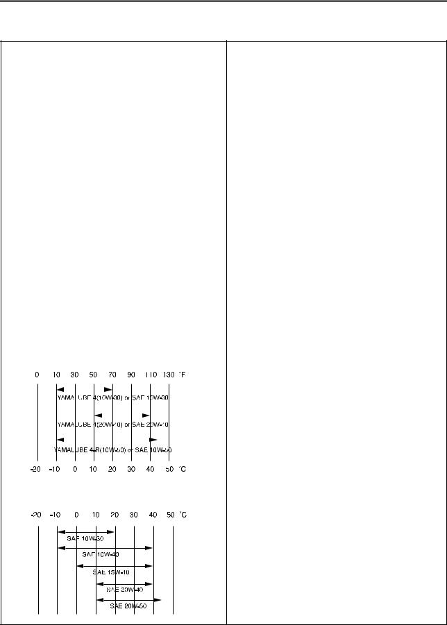
Engine oil |
(For CDN) |
|
||||||
|
|
|
|
|
|
|
Yamalube 4, SAE10W30 or SAE20W40 |
|
|
|
|
|
|
|
|
Yamalube 4-R, SAE10W50 |
|
|
|
|
|
|
|
|
API service SG type or higher, |
|
|
|
|
|
|
|
|
||
|
|
|
|
|
|
|
JASO standard MA |
|
|
|
|
|
|
|
|
|
|
|
|
|
|
|
|
|
|
|
(Except for CDN)
SAE10W30, SAE10W40, SAE15W40, SAE20W40 or SAE20W50
API service SG type or higher, JASO standard MA
2-1

|
GENERAL SPECIFICATIONS |
|
|
|
|
|
|
|
Oil capacity: |
|
|
Engine oil |
|
|
Periodic oil change |
0.95 L (0.84 Imp qt, 1.00 US qt) |
|
With oil filter replacement |
1.0 L (0.88 Imp qt, 1.06 US qt) |
|
Total amount |
1.2 L (1.06 Imp qt, 1.27 US qt) |
|
|
|
|
Coolant capacity (including all routes): |
1.0 L (0.88 Imp qt, 1.06 US qt) |
|
|
|
|
Air filter: |
Wet type element |
|
|
|
|
Fuel: |
|
|
Type |
Premium unleaded gasoline only with a research octane |
|
|
number of 95 or higher. |
|
Tank capacity |
8.0 L (1.76 Imp gal, 2.11 US gal) |
|
Reserve |
1.1 L (0.24 Imp gal, 0.29 US gal) |
|
|
|
|
Carburetor: |
|
|
Type |
FCR-MX39 |
|
Manufacturer |
KEIHIN |
|
|
|
|
Spark plug: |
|
|
Type/manufacturer |
CR8E/NGK (resistance type) |
|
Gap |
0.7–0.8 mm (0.028–0.031 in) |
|
|
|
|
Clutch type: |
Wet, multiple-disc |
|
|
|
|
Transmission: |
|
|
Primary reduction system |
Gear |
|
Primary reduction ratio |
61/23 (2.652) |
|
Secondary reduction system |
Chain drive |
|
Secondary reduction ratio |
50/13 (3.846) |
|
Transmission type |
Constant mesh, 5-speed |
|
Operation |
Left foot operation |
|
Gear ratio: |
|
|
1st |
29/12 (2.417) |
|
2nd |
26/15 (1.733) |
|
3rd |
21/16 (1.313) |
|
4th |
21/20 (1.050) |
|
5th |
21/25 (0.840) |
|
|
|
|
Chassis: |
CDN, ZA |
AUS, NZ |
|
|
|
Frame type |
Semi double cradle |
← |
Caster angle |
27.3 ° |
27.0 ° |
Trail |
117 mm (4.61 in) |
116 mm (4.57 in) |
|
|
|
Tire: |
|
|
Type |
With tube |
|
Size (front) |
80/100-21 51M (CDN, ZA) |
|
|
90/90-21 54R (AUS, NZ) |
|
Size (rear) |
110/100-18 64M (CDN, ZA) |
|
|
130/90-18 69R (AUS, NZ) |
|
Tire pressure (front and rear) |
100 kPa (1.0 kgf/cm2, 15 psi) |
|
2 |
2-2
|
MAINTENANCE SPECIFICATIONS |
|
|
|
|
Brake: |
|
Front brake type |
Single disc brake |
Operation |
Right hand operation |
Rear brake type |
Single disc brake |
Operation |
Right foot operation |
|
|
Suspension: |
|
Front suspension |
Telescopic fork |
Rear suspension |
Swingarm (link type monocross suspension) |
|
|
Shock absorber: |
|
Front shock absorber |
Coil spring/oil damper |
Rear shock absorber |
Coil spring/gas, oil damper |
|
|
Wheel travel: |
|
Front wheel travel |
300 mm (11.8 in) |
Rear wheel travel |
305 mm (12.0 in) |
|
|
Electrical: |
|
Ignition system |
CDI |
Generator system |
AC magneto |
Battery type |
YTZ7S (F) |
Battery voltage/capacity |
12V/6 AH |
Specific gravity |
1.310 |
|
|
Headlight type: |
Quartz bulb (halogen) |
|
|
Bulb wattage × quantity: |
|
Headlight |
12 V 35/36.5 W × 1 |
Taillight |
12 V 1.6/0.3 W × 1 |
MAINTENANCE SPECIFICATIONS
ENGINE
Item |
Standard |
Limit |
|
|
|
Cylinder head: |
|
|
Warp limit |
---- |
0.05 mm (0.002 |
|
|
in) |
Cylinder: |
|
|
Bore size |
95.00–95.01 mm (3.7402–3.7406 in) |
---- |
Out of round limit |
---- |
0.05 mm (0.002 |
|
|
in) |
2-3
MAINTENANCE SPECIFICATIONS
|
|
Item |
Standard |
Limit |
||||
|
|
|
|
|
|
|
|
|
Camshaft: |
|
|
||||||
Drive method |
Chain drive (Left) |
---- |
||||||
Camshaft cap inside diameter |
22.000–22.021 mm (0.8661–0.8670 in) |
---- |
||||||
Camshaft outside diameter |
21.959–21.972 mm (0.8645–0.8650 in) |
---- |
||||||
Shaft-to-cap clearance |
0.028–0.062 mm (0.0011–0.0024 in) |
0.08 mm (0.003 |
||||||
|
|
|
|
|
|
|
|
in) |
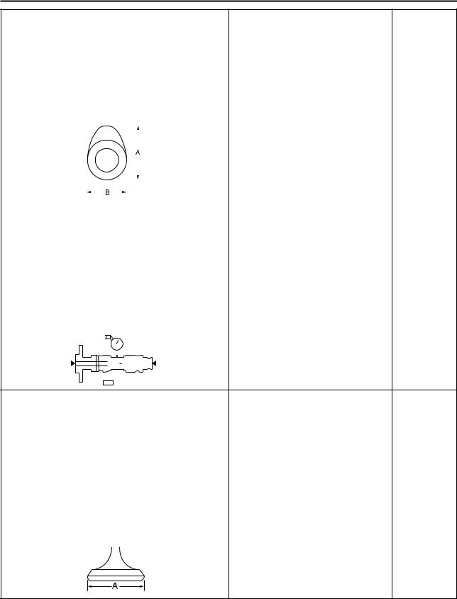
Cam dimensions |
|
|
||||||
|
|
|
|
|
|
|
|
|
|
|
|
|
|
|
|
|
|
|
|
|
|
|
|
|
|
|
|
|
|
|
|
|
|
|
|
|
|
|
|
|
|
|
|
|
|
|
|
|
|
|
|
|
|
|
|
|
|
|
|
|
|
|
Intake "A" |
30.100–30.200 mm (1.1850–1.1890 in) |
30.000 mm |
|
|
(1.1811 in) |
Intake "B" |
22.450–22.550 mm (0.8839–0.8878 in) |
22.350 mm |
|
|
(0.8799 in) |
Exhaust "A" |
30.200–30.300 mm (1.1890–1.1929 in) |
30.100 mm |
|
|
(1.1850 in) |
Exhaust "B" |
22.450–22.550 mm (0.8839–0.8878 in) |
22.350 mm |
|
|
(0.8799 in) |
Camshaft runout limit |
---- |
0.03 mm |
|
|
(0.0012 in) |
|
|
|
|
|
|
|
|
|
|
|
|
|
|
|
|
|
|
|
|
|
|
|
|
|
|
|
|
|
|
|
|
|
|
|
|
|
|
|
|
|
|
|
|
|
|
|
|
|
|
|
|
|
|
|
|
|
|
|
|
Timing chain: |
|
|
|||||||
Timing chain type/No. of links |
98XRH2010-118M/118 |
---- |
|||||||
Timing chain adjustment method |
Automatic |
---- |
|||||||
|
|
|
|
|
|
|
|
|
|
Valve, valve seat, valve guide: |
|
|
|||||||
Valve clearance (cold) |
|
|
|||||||
IN |
0.10–0.15 mm (0.0039–0.0059 in) |
---- |
|||||||
EX |
0.20–0.25 mm (0.0079–0.0098 in) |
---- |
|||||||
Valve dimensions: |
|
|
|||||||
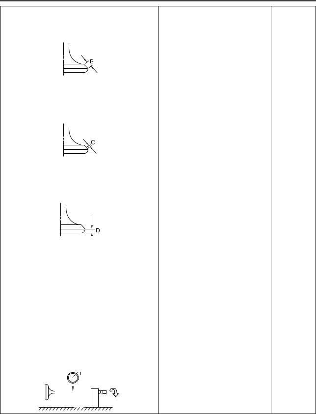
"A" head diameter (IN) |
26.9–27.1 mm (1.0591–1.0669 in) |
---- |
|||||||
"A" head diameter (EX) |
27.9–28.1 mm (1.0984–1.1063 in) |
---- |
|||||||
2-4
MAINTENANCE SPECIFICATIONS
Item |
Standard |
Limit |
|
|
|
"B" face width (IN) |
2.26 mm (0.089 in) |
---- |
"B" face width (EX) |
2.26 mm (0.089 in) |
---- |
"C" seat width (IN) |
0.9–1.1 mm (0.0354–0.0433 in) |
1.6 mm (0.0630 |
|
|
in) |
"C" seat width (EX) |
0.9–1.1 mm (0.0354–0.0433 in) |
1.6 mm (0.0630 |
|
|
in) |
"D" margin thickness (IN) |
1 mm (0.0394 in) |
0.85 mm (0.033 |
|
|
in) |
"D" margin thickness (EX) |
1 mm (0.0394 in) |
0.85 mm (0.033 |
|
|
in) |
Stem outside diameter (IN) |
|
|
4.475–4.490 mm (0.1762–0.1768 in) |
4.445 mm |
|||||||||||
|
|
|
|
|
|
|
|
|
|
|
|
|
|
|
(0.1750 in) |
Stem outside diameter (EX) |
|
|
4.965–4.980 mm (0.1955–0.1961 in) |
4.935 mm |
|||||||||||
|
|
|
|
|
|
|
|
|
|
|
|
|
|
|
(0.1943 in) |
Guide inside diameter (IN) |
|
|
4.500–4.512 mm (0.1772–0.1776 in) |
4.550 mm |
|||||||||||
|
|
|
|
|
|
|
|
|
|
|
|
|
|
|
(0.1791 in) |
Guide inside diameter (EX) |
|
|
5.000–5.012 mm (0.1969–0.1973 in) |
5.050 mm |
|||||||||||
|
|
|
|
|
|
|
|
|
|
|
|
|
|
|
(0.1988 in) |
Stem-to-guide clearance (IN) |
|
|
0.010–0.037 mm (0.0004–0.0015 in) |
0.08 mm (0.003 |
|||||||||||
|
|
|
|
|
|
|
|
|
|
|
|
|
|
|
in) |
Stem-to-guide clearance (EX) |
|
|
0.020–0.047 mm (0.0008–0.0019 in) |
0.10 mm (0.004 |
|||||||||||
|
|
|
|
|
|
|
|
|
|
|
|
|
|
|
in) |
Stem runout limit |
---- |
0.01 mm |
|||||||||||||
|
|
|
|
|
|
|
|
|
|
|
|
|
|
|
(0.0004 in) |
|
|
|
|
|
|
|
|
|
|
|
|
|
|
|
|
|
|
|
|
|
|
|
|
|
|
|
|
|
|
|
|
|
|
|
|
|
|
|
|
|
|
|
|
|
|
|
|
|
|
|
|
|
|
|
|
|
|
|
|
|
|
|
|
|
|
|
|
|
|
|
|
|
|
|
|
|
|
|
|
2-5
 Loading...