


PROFESSIONAL DISC CAMCORDER
PDW-F800
PDW-700
OPERATION MANUAL [English]
1st Edition (Revised 4)

WARNING
To reduce the risk of fire or electric shock, do not expose this apparatus to rain or moisture.
To avoid electrical shock, do not open the cabinet. Refer servicing to qualified personnel only.
This Professional Disc Camcorder is classified as a CLASS 1 LASER PRODUCT.
Laser diode properties
Wavelength: 400 to 410 nm Emission duration: Continuous
Laser output power: 135 mW (max. of pulse peak), 65 mW (max. of CW) Standard: IEC60825-1 (2001)
Egenskaber for laserdiode
Bølgelængde: 400 til 410 nm Strålingsvarighed: Kontinuerlig Afgivet lasereffekt: 135 mW (maks stråletoppunkt), 65 mW (maks ved kontinuerlig stråling)
Standard: IEC60825-1 (2001)
Tekniska data för laserdiod
Våglängd: 400 till 410 nm Emissionslängd: Kontinuerlig Laseruteffekt: 135 mW (max. för pulstopp), 65 mW (max. för kontinuerlig våg)
Standard: IEC60825-1 (2001)
Egenskaper for laserdiode
Bølgelengde: 400 til 410 nm Strålingsvarighet: Uavbrutt Utgangseffekt for laser: 135 mW (maks av pulshøyde), 65 mW (maks av CW) Standard: IEC60825-1 (2001)
This label is located inside the outside panel of the unit.
Denna etikett finns på apparatens ovansida.
Denne mærkat sidder på apparatets øverste panel.
Tämä kyltti sijaitsee laitteen yläpinnalla.
Dette merket er plassert på oversiden av produktet.
CAUTION
The use of optical instruments with this product will increase eye hazard.
Use of controls or adjustments or performance of procedures other than those specified herein may result in hazardous radiation exposure.
VAROITUS!
LAITTEEN KÄYTTÄMINEN MUULLA KUIN TÄSSÄ KÄYTTÖOHJEESSA MAINITULLA TAVALLA SAATTAA ALTISTAA KÄYTTÄJÄN TURVALLISUUSLUOKAN 1 YLITTÄVÄLLE NÄKYMÄTTÖMÄLLE LASERSÄTEILYLLE.
VARNING
OM APPARATEN ANVÄNDS PÅ ANNAT SÄTT ÄN I DENNA BRUKSANVISNING SPECIFICERATS, KAN ANVÄNDAREN UTSÄTTAS FÖR OSYNLIG LASERSTRÅLNING, SOM ÖVERSKRIDER GRÄNSEN FÖR LASERKLASS 1.
WARNING
Excessive sound pressure from earphones and headphones can cause hearing loss. In order to use this product safely, avoid prolonged listening at excessive sound pressure levels.
2

For the customers in the U.S.A.
This equipment has been tested and found to comply with the limits for a Class B digital device, pursuant to Part 15 of the FCC Rules. These limits are designed to provide reasonable protection against harmful interference in a residential installation. This equipment generates, uses, and can radiate radio frequency energy and, if not installed and used in accordance with the instructions, may cause harmful interference to radio communications. However, there is no guarantee that interference will not occur in a particular installation. If this equipment does cause harmful interference to radio or television reception, which can be determined by turning the equipment off and on, the user is encouraged to try to correct the interference by one or more of the following measures:
—Reorient or relocate the receiving antenna.
—Increase the separation between the equipment and receiver.
—Connect the equipment into an outlet on a circuit different from that to which the receiver is connected.
—Consult the dealer or an experienced radio/TV technician for help.
You are cautioned that any changes or modifications not expressly approved in this manual could void your authority to operate this equipment.
All interface cables used to connect peripherals must be shielded in order to comply with the limits for a digital device pursuant to Subpart B of Part 15 of FCC Rules.
If you have any questions about this product, you may call;
Sony Customer Information Service Center 1-800-222-7669 or http://www.sony.com/
Declaration of Conformity
Trade Name: |
SONY |
Model: |
PDW-F800, PDW-700 |
Responsible party: |
|
|
Sony Electronics Inc. |
Address: |
16530 Via Esprillo, |
|
San Diego, CA 92127 |
|
U.S.A. |
Telephone Number:
858-942-2230
This device complies with part 15 of the FCC Rules. Operation is subject to the following two conditions: (1) this device may not cause harmful interference, and
(2) this device must accept any interference received, including interference that may cause undesired operation.
For the customers in Canada
This Class B digital apparatus complies with Canadian ICES-003.
For the State of California, USA only
Perchlorate Material - special handling may apply, See www.dtsc.ca.gov/hazardouswaste/perchlorate Perchlorate Material : Lithium battery contains perchlorate.
For the customers in Europe
This product with the CE marking complies with the EMC Directive issued by the Commission of the European Community. Compliance with this directive implies conformity to the following European standards:
•EN55103-1: Electromagnetic Interference (Emission)
•EN55103-2: Electromagnetic Susceptibility (Immunity)
This product is intended for use in the following Electromagnetic Environments: E1 (residential), E2 (commercial and light industrial), E3 (urban outdoors), E4 (controlled EMC environment, ex. TV studio).
The manufacturer of this product is Sony Corporation, 1-7-1 Konan, Minato-ku, Tokyo, Japan.
The Authorized Representative for EMC and product safety is Sony Deutschland GmbH, Hedelfinger Strasse 61, 70327 Stuttgart,
3

Germany. For any service or guarantee matters please refer to the addresses given in separate service or guarantee documents.
For the customers in Taiwan only
4

Table of Contents |
|
Foreword .................................................................................................... |
11 |
Before use........................................................................................ |
11 |
Marks for model-specific functions ................................................ |
11 |
Chapter 1 : Overview |
|
Features ...................................................................................................... |
12 |
Locations and Functions of Parts and Controls...................................... |
15 |
Power supply................................................................................... |
15 |
Accessory attachments .................................................................... |
16 |
Operating and connectors section ................................................... |
17 |
HDVF-20A viewfinder (optional)................................................... |
31 |
Status display on the viewfinder screen .......................................... |
32 |
Chapter 2 : Preparations |
|
Preparing a Power Supply ........................................................................ |
38 |
Using a battery pack........................................................................ |
38 |
Using AC power.............................................................................. |
39 |
Attaching the Viewfinder .......................................................................... |
39 |
Attaching the HDVF-20A/C35W ................................................... |
39 |
Adjusting the viewfinder position................................................... |
40 |
Moving the viewfinder shoe up....................................................... |
40 |
Using the BKW-401 Viewfinder Rotation Bracket ........................ |
41 |
Detaching the eyepiece ................................................................... |
42 |
Adjusting the viewfinder focus and screen ..................................... |
42 |
Setting the Area of Use .............................................................................. |
43 |
Setting the Date/Time of the Internal Clock ........................................... |
44 |
Mounting the Lens..................................................................................... |
45 |
Adjusting the Flange Focal Length .......................................................... |
46 |
Preparing the Audio Input System .......................................................... |
47 |
Connecting a microphone to the MIC IN connector....................... |
47 |
Connecting microphones to the AUDIO IN connectors ................. |
48 |
Attaching a UHF portable tuner (for a UHF wireless microphone |
|
system) ...................................................................................... |
49 |
Connecting line input audio equipment .......................................... |
51 |
Table of Contents |
5 |
|
|

Tripod Mounting ....................................................................................... |
52 |
Connecting a Video Light ......................................................................... |
53 |
Using the Shoulder Strap .......................................................................... |
53 |
Adjusting the Shoulder Pad Position ....................................................... |
54 |
Connecting the Remote Control Unit ...................................................... |
55 |
Chapter 3 : Adjustments and Settings for Shooting |
|
Setting the Recording Format .................................................................. |
58 |
Setting the system frequency .......................................................... |
58 |
Setting the video recording format.................................................. |
59 |
Mixed recording of clips in different formats on the same disc ..... |
59 |
Adjusting the Black Balance and the White Balance ............................. |
60 |
Adjusting the black balance ............................................................ |
60 |
Adjusting the white balance ............................................................ |
61 |
Setting the Electronic Shutter................................................................... |
66 |
Shutter modes.................................................................................. |
66 |
Selecting the shutter mode and shutter speed ................................. |
67 |
Changing the Reference Value for Automatic Iris Adjustment............ |
70 |
Adjusting the Audio Level ........................................................................ |
72 |
Manually adjusting the audio levels of the audio inputs from the |
|
AUDIO IN CH1/CH2 connectors............................................. |
72 |
Manually adjusting the audio level of the MIC IN connector ........ |
73 |
Recording audio on channels 3 and 4 ............................................. |
73 |
Setting the Time Data................................................................................ |
75 |
Setting the timecode........................................................................ |
75 |
Setting the user bits ......................................................................... |
75 |
Synchronizing the timecode............................................................ |
76 |
Chapter 4 : Shooting |
|
Handling Discs ........................................................................................... |
79 |
Discs used for recording and playback ........................................... |
79 |
Notes on handling ........................................................................... |
79 |
Write-protecting discs ..................................................................... |
79 |
Loading and unloading a disc ......................................................... |
80 |
Formatting a disc............................................................................. |
81 |
Handling of discs when recording does not end normally (salvage |
|
function).................................................................................... |
81 |
Basic Procedure for Shooting ................................................................... |
83 |
6 Table of Contents

Playing back the recorded clip ........................................................ |
85 |
Deleting the recorded clip ............................................................... |
86 |
Using the Freeze Mix function........................................................ |
87 |
Using the Focus Assist function...................................................... |
87 |
Advanced Operations for Shooting.......................................................... |
88 |
Recording essence marks ................................................................ |
88 |
Setting clip flags with switches....................................................... |
89 |
Setting the thumbnail image at recording time ............................... |
89 |
Starting a shoot with a few seconds of pre-stored picture data (Picture |
|
Cache function)......................................................................... |
89 |
Time-lapse video (Interval Rec function) ....................................... |
91 |
Shooting with Slow & Quick Motion ............................................. |
95 |
Exchanging discs while recording (Disc Exchange Cache function) |
|
.................................................................................................. |
96 |
Recording with the Clip Continuous Rec function ......................... |
97 |
Retaking the most recent clip.......................................................... |
97 |
Assigning user-defined clip titles automatically ............................. |
98 |
Assigning user-defined names to clips and clip lists .................... |
101 |
Using planning metadata............................................................... |
102 |
Recording video from external devices......................................... |
105 |
Using the Live Logging function .................................................. |
106 |
Recording proxy data .................................................................... |
107 |
Chapter 5 : Operations in GUI Screens |
|
Overview................................................................................................... |
111 |
Switching between GUI screens ................................................... |
111 |
Information and controls in thumbnail screens............................. |
113 |
Displaying menus.......................................................................... |
116 |
GUI screen operations................................................................... |
120 |
Thumbnail Operations ............................................................................ |
121 |
Selecting thumbnails ..................................................................... |
121 |
Searching with thumbnails............................................................ |
121 |
Playing the scene you have found................................................. |
124 |
Selecting clips by type (Filter Clips function) .............................. |
124 |
Selecting the information displayed on thumbnails ...................... |
126 |
Changing clip index pictures......................................................... |
126 |
Checking clip properties ............................................................... |
127 |
Setting clip flags............................................................................ |
130 |
Locking (write-protecting) clips ................................................... |
130 |
Deleting clips ................................................................................ |
131 |
Scene Selection (Clip List Editing)......................................................... |
132 |
What is scene selection?................................................................ |
132 |
Creating and editing clip lists........................................................ |
133 |
Table of Contents |
7 |
|
|

Managing clip lists ........................................................................ |
138 |
Disc Operations........................................................................................ |
139 |
Checking disc properties ............................................................... |
139 |
Using planning metadata............................................................... |
140 |
Checking user-defined essence marks .......................................... |
141 |
Formatting discs ............................................................................ |
142 |
Displaying disc and clip properties in a web browser................... |
142 |
Transferring clips (Direct FTP function) .............................................. |
146 |
Preparations for clip transfers ....................................................... |
147 |
Uploading clips ............................................................................. |
147 |
Downloading clips ........................................................................ |
151 |
Copying clips directly between XDCAM devices........................ |
151 |
Shortcut List............................................................................................. |
153 |
Chapter 6 : Menu Displays and Detailed Settings |
|
Menu Organization.................................................................................. |
154 |
TOP menu and top-level menus.................................................... |
155 |
Menu List.................................................................................................. |
157 |
OPERATION menu ...................................................................... |
157 |
PAINT menu ................................................................................. |
171 |
MAINTENANCE menu................................................................ |
180 |
FILE menu .................................................................................... |
199 |
DIAGNOSIS menu ....................................................................... |
203 |
Menu Operations ..................................................................................... |
205 |
Displaying menus.......................................................................... |
205 |
Basic menu operations .................................................................. |
205 |
Using the USER menu (example menu operation) ....................... |
208 |
Editing the USER menu ................................................................ |
209 |
Resetting USER menu settings to the standard settings................ |
213 |
Setting the Status Display on the Viewfinder Screen and the LCD |
|
Monitor............................................................................................... |
213 |
Selecting the display items............................................................ |
213 |
Change confirmation/adjustment progress messages.................... |
214 |
Setting the marker display............................................................. |
215 |
Setting the viewfinder ................................................................... |
216 |
Recording shot data superimposed on the color bars.................... |
217 |
Setting the shot ID......................................................................... |
217 |
Displaying the status confirmation screens................................... |
218 |
Adjustments and Settings from Menus.................................................. |
220 |
Setting gain values for the GAIN selector positions..................... |
220 |
Selecting the output signals........................................................... |
220 |
8 Table of Contents

Assigning functions to ASSIGN switches .................................... |
221 |
Setting power saving functions ..................................................... |
224 |
Setting up a wireless LAN ............................................................ |
224 |
Setting the color temperature manually ........................................ |
227 |
Specifying an offset for the auto white balance setting ................ |
227 |
Selecting the lens file .................................................................... |
228 |
Setting the UMID data .................................................................. |
228 |
Chapter 7 : Saving and Loading User Setting Data |
|
Handling the “Memory Stick”................................................................ |
230 |
Saving and Recalling User Files ............................................................. |
231 |
Saving user menu data to the “Memory Stick”............................. |
231 |
Loading saved data from a “Memory Stick”................................. |
233 |
Returning the user file settings to the standard settings................ |
234 |
Saving and Loading Scene Files ............................................................. |
234 |
Saving a scene file......................................................................... |
234 |
Loading scene files........................................................................ |
236 |
Returning the scene file settings to the standard settings.............. |
237 |
Jumping to a File-Related Menu Page When Inserting a “Memory Stick” |
|
............................................................................................................. |
237 |
Chapter 8 : File Operations |
|
Overview................................................................................................... |
239 |
Directory structure ........................................................................ |
239 |
File operation restrictions.............................................................. |
240 |
File Operations in File Access Mode (for Windows) ............................ |
245 |
Making FAM connections............................................................. |
245 |
Operating on files.......................................................................... |
246 |
Exiting file operations................................................................... |
246 |
File Operations in File Access Mode (for Macintosh) .......................... |
247 |
Making FAM connections............................................................. |
247 |
Operating on files.......................................................................... |
248 |
Exiting file operations................................................................... |
248 |
FTP File Operations ................................................................................ |
249 |
Making FTP connections .............................................................. |
249 |
Command list ................................................................................ |
250 |
Recording Continuous Timecode with FAM and FTP Connections .. 255
Table of Contents |
9 |
|
|

Chapter 9 : Maintenance |
|
Testing the Camcorder before Shooting................................................ |
256 |
Preparations for testing ................................................................. |
256 |
Testing the camera ........................................................................ |
256 |
Testing the VDR ........................................................................... |
258 |
Maintenance ............................................................................................. |
260 |
Cleaning the viewfinder ................................................................ |
260 |
Note about the battery terminal..................................................... |
261 |
Operation Warnings................................................................................ |
262 |
Appendix
Important Notes on Operation ............................................................... |
270 |
Specifications............................................................................................ |
272 |
General .......................................................................................... |
272 |
Video camera section .................................................................... |
272 |
Optical disc drive section .............................................................. |
273 |
Supplied accessories...................................................................... |
274 |
Recommended additional equipment............................................ |
274 |
Chart of Optional Components and Accessories .................................. |
276 |
Using PDZ-1 Proxy Browsing Software ................................................ |
277 |
List of Supported USB Keyboards......................................................... |
278 |
Recommended USB Flash Drives (As of June 2009) ............................ |
281 |
Trademarks and Licenses ....................................................................... |
281 |
MPEG-4 Visual Patent Portfolio License ..................................... |
281 |
MPEG-2 Video Patent Portfolio License...................................... |
281 |
About IJG (Independent JPEG Group) ......................................... |
282 |
Character display software “iType” .............................................. |
282 |
About libupnp................................................................................ |
282 |
About OpenSSL ............................................................................ |
282 |
About a “Memory Stick” ........................................................................ |
286 |
Index.......................................................................................................... |
288 |
10 Table of Contents
Foreword
Before use
After purchasing this unit, before operating, it is necessary to set the region of use.
(Unless this setting is made, the unit will not operate.)
For details of these settings, see “Setting the Area of Use” on page 43.
Note
Before attaching/removing optional components or accessories to/from the camcorder, be sure to turn the power of the camcorder off.
Marks for model-specific functions
In this manual, functions that are supported only by the PDW-F800 or only by the PDW-700 are indicated by the following marks.
[F800]: PDW-F800 [700]: PDW-700
Foreword 11

|
|
|
|
|
|
|
|
Chapter1 |
Overview |
||
1 Chapter |
|||||
|
|
|
|
||
Overview |
|
|
|
|
|
|
Features |
||||
|
|
||||
|
|
|
|
|
|
|
|
|
|
|
|
New 2/3-inch full-HD “PowerHAD FX”
CCDs
•IT (Interline Transfer) 2/3-inch progressive image sensors with 2.2 million pixels, for full
HD resolution (1920 × 1080)
•Newly developed “PowerHAD FX” CCDs, featuring a signal processing ASIC with 14-bit
A/D converters
These new image sensor technologies enable the capture of very high-quality images, with F11
(59.94i) and F12 (50i) sensitivity and an SN ratio of 59 dB. 1)
1)With noise suppression on (off value is 54 dB) Noise suppression uses proprietary Sony signal processing technology to suppress noise in highfrequency regions.
Mechanisms for high reliability
A new duct cooling system prevents overheating inside the unit and on its surfaces, for greater reliability in high-temperature environments. Reliability is also enhanced by the drip-proof design.
Recording can continue even when the unit is subjected to jarring shocks, because data is stored in shockproof memory before being recorded to the media. Reliable recording is ensured by a recording verification function, similar to the confidence playback function of tape recorders, qualifying the unit for use in demanding broadcast applications.
Multi-format support
The unit supports six system frequencies (1080/ 59.94i, 1080/29.97P, 1080/50i, 1080/25P, 1080/ 23.98P 1), 720/59.94P 2), and 720/50p), offering the flexibility needed for worldwide HD recording. It also supports recording and playback of SD signals (both NTSC and PAL) 3),
12 Features
allowing a stepwise transition from SD to HD systems.
A multi-format conversion function enables upand down-conversion between SD and HD, and cross-conversion between 1080 and 720.
Squeeze, edge cropping, and letterbox are selectable as the aspect pattern in upand downconversion between SD and HD.
1)The PDW-700 requires installation of the optional CBKZ-FC02 23.98P Record and Playback Software and a verification key. For details, contact a Sony service representative.
2)When the current recording format is 720/59.94P, you can shoot in 23.98P mode. However, as soon as it is shot, the video undergoes 2-3 pulldown and is recorded as 59.94P.
3)The PDW-700 requires installation of the optional CBKZ-MD01 SD Record and Playback Software and a verification key. For details, contact a Sony service representative.
Note
It is not possible to combine material recorded in different frame frequency groups on single disc (see page 59).
Recording of more than 90 minutes of high-quality video and audio data
•Signals captured by the full-HD (1920 × 1080)
image sensors are recorded in MPEG HD422 format 1) for consistently high image quality. 2)
•The unit supports recording of four audio channels 3) sampled at 24 bits for high quality.
•Dual-layer Professional discs can record about 95 minutes of high-quality video and audio
data.
The generous recording times and the highquality of the recorded video and audio allow this unit to meet the most stringent requirements of production teams in a wide range of genres, from news gathering through digital cinema and program production.
The unit supports a variety of HD formats, including formats with 720 lines of resolution.
1)The MPEG-2 422P@HL codec performs 4:2:2 sampling and records at a video bit rate of 50 Mbps.
2)Image compression uses the MPEG-2 Long GOP system.

3)The PDW-HD1500 supports recording of up to eight channels in MPEG HD422 format.
Format compatibility with earlier models
The unit is capable of recording in the MPEG-2 MP@HL 35/25 Mbps formats used by earlier XDCAM HD devices. These formats offer longer recording times than the MPEG-2 422P@HL 50 Mbps format.
It is also capable of recording and playback in the MPEG IMX 50/40/30 Mbps and DVCAM 25 Mbps formats. 1)
1)The PDW-700 requires installation of the optional CBKZ-MD01 SD Record and Playback Software and a verification key. For details, contact a Sony service representative.
Rich selection of interfaces
•HDSDI and SDSDI output connectors: Allow free combination of HDSDI and SDSDI signals. Timecode and other text data can be superimposed on signals from one of the two interfaces.
•Composite signal output connector
•Selectable video input connectors: The unit is designed to support recording in every type of environment, including reporting by pool coverage teams. The optional CBK-HD01 HD/ SD SDI Input Board or CBK-SC02 Analog Composite Input Board can be installed to enable selection of HD SDI/SD SDI or composite signals. SD signals can be upconverted and recorded as HD signals.
•Gen-lock input connector: Enables synchronized operation of multiple units, with synchronization possible to either VBS or HD- Y signals.
•Audio input connectors: Supports AES/EBU signal input, in addition to microphone input, +48 V microphone input, and line input.
•Timecode input and output connectors
•Network connector and i.LINK connector: Enable transfer of MXF-format files. Material recorded in the field can be transferred to a computer for immediate cut editing with the supplied PDZ-1 Proxy Browsing Software Version 2.7.
•USB connector: Enables use of a Windows USB keyboard or mouse. You can also connect a USB flash drive to record proxy data or load planning metadata, or connect the optional
CBK-WA01 Wi-Fi adapter to connect to a wireless LAN network.
Features for improved performance under various shooting conditions
Picture Cache function
The unit can utilize its internal memory to continuously record the current video input, allowing recording to commence a certain time (2 to 30 seconds) in advance of the time when the recording button is pressed, and allowing discs to be exchanged seamlessly without interrupting the recording.
[F800]
Two optical filters
The unit is equipped with separate CC filters and ND filters. Two filters can be used simultaneously.
[700]
Color temperature filters
Color temperature filters are composed of electronic circuits, allowing smooth and instantaneous switching – an important advantage in ENG (Electronic News Gathering) – and linked operation with ND filters. Dedicated switches are provided to enable rapid switching between color temperature filters, and absolute color temperature settings can be recalled instantly without being effected by white balance settings.
Noise suppression circuits
New noise suppression circuits offer improved performance under difficult evening or nighttime shooting conditions.
Slow shutter function
A maximum of 16 frames can be accumulated using the slow shutter function. In low light levels this allows clear and noiseless video to be shot, and provides a fantasy video effect with ghost images.
Time lapse function (interval recording)
Using this function slow-moving subjects can be shot with the movement compressed in time. This is convenient for many applications, such as monitoring plant growth, or the progress of a construction site.
Overview 1 Chapter
Features 13

Overview 1 Chapter
[F800]
Slow & quick motion function 1)
This function allows the shooting frame rate to be different from the playback frame rate, for the same effect as overcranking or undercranking a film camera. Unlike low-speed or high-speed playback of normally shot video, this provides a smooth slow-motion effect, or action speeded up beyond actual speed.
1)This function is available when the recording format is MPEG HD422, 50 Mbps, and the resolution/system frequency is 1080/23.98P, 1080/25P, or 1080/29.97P.
Freeze Mix function
This allows a still image from previously captured video to be aligned with the current video output from the camera. Thus you can adjust the camera position to get exactly the same framing for new shots. For example, this function makes it easy to frame summer and winter shots of a landscape scene in exactly the same way.
Digital extender function
This magnifies the center section of the video. It utilizes electronic processing, which prevents the decrease in sensitivity (F-drop) that occurs when the lens extender function is used.
Focus magnification function
This magnifies the center section of the viewfinder by a factor of about two. It enables highly precise focus adjustments in HD shooting.
[F800]
Image inversion function 1)
This cancels the image inversion that can occur when a cinema lens converter is mounted.
1)This function is available when the resolution/system frequency is 1080/23.98P, 1080/25P, or 1080/29.97P.
Assignable switches
Frequently used function can be assigned to switches for quick and convenient operation.
Hyper gamma
This enables a wide dynamic range without using the Knee function, by smoothly compressing the high-luminance range.
Supports new digital wireless microphone system
The new digital wireless microphone system offers high-quality, superior resistance to noise, and simultaneous multi-channel operation. Installation of the DWR-S01D Digital Wireless
Receiver 1) enables simultaneous reception of two channels.
1)These products are not available in countries where they are prohibited by radio frequency regulations.
3.5-inch color LCD monitor
The 3.5-inch color LCD monitor displays easy- to-read audio meters, menus, disc and battery capacity indications, and thumbnails of clips stored on disc.
Inherits unique features of XDCAM series
The unit inherits the workflow features of the XDCAM series, including thumbnail display and metadata management, and improves them by introducing an improved man-machine interface. Metadata includes new user-settable clip flags (OK/NG/KEEP) in addition to the existing Rec Start essence marks. The new metadata types enable more efficient workflows when clips recorded on this unit are edited on nonlinear editing systems.
14 Features

Locations and Functions
of Parts and Controls
Power supply
1 |
2 |
3 4 5 |
a LIGHT switch
Determines how a video light connected to the LIGHT connector (see page 16) is turned on and off.
AUTO: When the POWER switch of the video light is in the on position, the video light is turned on automatically while the camcorder is recording.
MANUAL: You can turn the video light on or off manually, using its own switch.
Notes
•When this switch is set to AUTO, at the beginning of the recording, the picture is recorded even though the lighting may fluctuate until the video light comes on. If the beginning of the recording is important, you should set this switch to MANUAL.
•To ensure proper operation of the video light, Sony recommends the use of the BP-GL95/L80S Battery Pack with the camcorder.
b POWER switch
Turns the main power supply on and off.
cDC IN (DC power input) connector (XLR type, 4-pin, male)
To operate the camcorder from an AC power supply, connect an optional DC power cord to this terminal and then connect the cord to the DC output terminal of the BC-L70, BC-L160, or another battery charger.
dDC OUT 12V (DC power output) connector (4-pin, female)
Supplies power for a WRR-860A/861/862 UHF Synthesized Diversity Tuner (not supplied) (maximum 0.5 A).
Do not connect any equipment other than the UHF synthesized diversity tuner.
e Battery attachment shoe
Attach a BP-GL95/GL65/L60S/L80S Battery Pack. Alternatively, you can attach an ACDN2B/DN10 AC Adaptor to operate the camcorder on AC power supply.
For details about how to attach the battery or AC adaptor, see “Preparing a Power Supply” on page 38. For information about attaching a synthesized tuner, see “Attaching a UHF portable tuner (for a UHF wireless microphone system)” on page 49.
Note
For your safety, and to ensure proper operation of the camcorder, Sony recommends the use of the following battery packs: BP-GL95, BP-GL65, BP-L60S, and BPL80S.
Overview 1 Chapter
Locations and Functions of Parts and Controls 15

Accessory attachments
Chapter |
1 |
23 4567 |
1 |
|
|
Overview |
|
|
|
8 9 0 qa qs qdqfqgqh qj qk |
|
|
|
ql |
|
a Shoulder strap fitting |
|
Attach the supplied shoulder strap (see page 53).
b Accessory fitting shoe
Attach an optional accessory such as a video light
(see page 53).
cViewfinder front-to-back positioning lever
To adjust the viewfinder position in the front-to- back direction, loosen this lever and the LOCK knob. After adjustment, retighten this lever and the LOCK knob.
d Viewfinder left-to-right positioning ring
Loosen this ring to adjust the left-to-right position of the viewfinder (see page 40).
e Viewfinder fitting shoe
Attach an optional viewfinder.
f VF (viewfinder) connector (20-pin)
Connect an optional viewfinder.
Consult a Sony representative for information about available viewfinders.
g Lens mount securing rubber
After locking the lens in position using the lens locking lever, fit this rubber over the lower of the two projections. This fixes the lens mount, preventing it from coming loose.
hViewfinder front-to-back positioning knob (LOCK knob)
Loosen this knob to adjust the front-to-back position of the viewfinder (see page 40).
i Fitting for optional microphone holder
Fit an optional CAC-12 Microphone Holder (see page 48).
j Shoulder pad
Raise the shoulder pad fixing lever to adjust the position in the front-to-rear direction. Adjust the position for maximum convenience when operating the unit on your shoulder.
For details of the adjustment, see “Adjusting the Shoulder Pad Position” on page 54.
kLIGHT (video light) connector (2-pin, female)
A video light with a maximum power consumption of 50 W, such as the Anton Bauer Ultralight 2 or equivalent can be connected (see page 53).
l Lens cable clamp
Clamp a lens cable.
mMIC IN (microphone input) (+48 V) connector (XLR type, 5-pin, female)
Connect a stereo microphone to this connector. The power (+48 V) is supplied via this connector.
n LENS connector (12-pin)
Connect a lens cable to this connector.
Note
When connecting the lens cable to this connector, power off this unit first.
16 Locations and Functions of Parts and Controls

o Tripod mount
When using the unit on a tripod, attach the tripod adaptor (optional).
p Lens mount (special bayonet mount)
Attach the lens.
Consult a Sony representative for information about available lenses.
q Lens locking lever
After inserting the lens in the lens mount, rotate the lens mount ring with this lever to lock the lens in position.
After locking the lens, be sure to use the lens mount securing rubber to prevent the lens from becoming detached.
r Lens mount cap
Remove by pushing up the lens locking lever. When no lens is mounted, keep this cap fitted for protection from dust.
sCA (camera adapter) connector (50pin)
Remove the connector cover, and connect the 50pin connector of the HDCA-702 MPEG TS Adaptor.
Refer to the Operation Manual of the HDCA-702 for more information about how to mount it.
Operating and connectors section
Front |
Chapter1 |
|
|
||
|
Overview |
|
|
3 |
|
|
4 |
|
1 |
5 |
|
2 |
6 |
|
7 |
||
|
||
a REC START (recording start) button |
||
Press to start recording. Press it again to stop recording. The effect is the same as that of the REC button on the lens.
b SHUTTER selector
Set to ON to use the electronic shutter. Flick to SELECT to switch the shutter speed or shutter mode setting within the range previously set with the menu. When this switch is operated, the new setting appears on the setting change/adjustment progress message display area for about three seconds.
For details about the shutter speed and shutter mode settings, see “Setting the Electronic Shutter” on page 66.
c FILTER selector
Switches between optical filters built into this unit.
When this selector is used with the menu item for filter selection display set to ON (see page 214), the new setting appears on the viewfinder screen for about three seconds.
[F800]
The PDW-F800 is equipped with two switchable filters. You can switch between four electrical CC filters and four ND filters.
Locations and Functions of Parts and Controls 17

Overview 1 Chapter
FILTER selector |
CC filter |
(outer knob) setting |
|
A |
Cross filter a) |
B |
3200K |
|
|
C |
4300K |
|
|
D |
6300K |
|
|
a)A type of special effect filter. A cross of light appears in the highlight section.
FILTER selector |
ND filter |
(inner knob) setting |
|
1 |
CLEAR (no filter) |
|
|
2 |
1/4 ND (reduces the |
|
amount of light to about |
|
1/4) |
3 |
1/16 ND(reduces the |
|
amount of light to about |
|
1/16) |
4 |
1/64 ND(reduces the |
|
amount of light to about |
|
1/64) |
[700]
The PDW-700 is equipped with one switchable filter. It is possible to switch between four ND filters.
FILTER selector |
ND filter |
|
setting |
|
|
1 |
CLEAR |
|
|
|
|
2 |
1/4 ND (attenuates light |
|
|
to approximately 1/ ) |
|
|
4 |
|
3 |
1/16 ND (attenuates light |
|
|
to approximately 1/ |
) |
|
16 |
|
4 |
1/64 ND (attenuates light |
|
|
to approximately 1/ |
) |
|
64 |
|
For the PDW-700, you can change a MAINTENANCE menu setting so that different white balance settings can be stored for different FILTER selector positions. This allows you to automatically obtain optimum white balance for the current shooting conditions in linkage with the filter selection.
For details, see “Adjusting the white balance” on page 61.
d MENU knob
Changes the page selection or a setting within the menu.
For details about how to use the MENU knob, see “Menu Operations” on page 205.
eEARPHONE jack (monaural, minijack)
You can monitor the E-E 1) sound during recording and playback sound during playback. When an alarm is indicated, you can hear the alarm sound through the earphone. You can use this with the EARPHONE jack on the rear of the unit at the same time. Plugging an earphone into the jack automatically cuts off the built-in speaker.
1)E-E: Abbreviation of “Electric-to-Electric”. In E-E mode, video and audio signals input to the camcorder are output after passing through internal electric circuits only. This can be used to check input signals.
fAUTO W/B BAL (automatic white/ black balance adjustment) switch
Activates the automatic white/black balance adjustment functions.
WHT: Adjusts the white balance automatically. If the WHITE BAL switch (see page 20) is set to A or B, the white balance setting is stored in the corresponding memory. If the WHITE BAL switch is set to PRST, the automatic white balance adjustment function does not operate.
BLK: Adjusts the black set and black balance automatically.
g MIC (microphone) LEVEL control
Adjusts the input level of audio channels 1, 2, 3 and 4.
For details, see “Adjusting the Audio Level” on page 72.
18 Locations and Functions of Parts and Controls
Right side (near the front)
1 |
2 3 4 |
5 |
|
|
6 7 8 9 |
|
|
0 |
qa |
qs |
|
|
|
MENU |
|
ON/ |
OFF |
CANCEL/PRST |
|
SEL |
ON |
ESCAPE |
|
STATUS |
|
|
|
OFF |
|
|
|
|
|
|
qd |
|
|
|
qf |
a ASSIGN (assignable) 1/2 switches |
|||
You can assign the desired functions to these switches on the ASSIGNABLE SW page of the OPERATION menu.
Nothing is assigned to these switches when the camcorder is shipped from the factory (equivalent to a selection of OFF in the menu).
For details, see “Assigning functions to ASSIGN switches” on page 221.
[F800]
b ASSIGN (assignable) 5 switch
You can assign the desired functions to these switches on the ASSIGNABLE SW page of the OPERATION menu.
Nothing is assigned to these switches when the camcorder is shipped from the factory (equivalent to a selection of OFF in the menu).
For details, see “Assigning functions to ASSIGN switches” on page 221.
[700]
b COLOR TEMP. (color temperature)
temperature for shooting. You can use this as an |
1Chapter |
|
button |
|
|
Press to light the button and change the color |
|
|
ASSIGN (assignable) switch (see page 221). |
Overview |
|
c ALARM (alarm tone volume |
||
|
||
adjustment) knob |
|
|
Controls the volume of the warning tone that is |
|
|
output via the built-in speaker or optional |
|
|
earphones. When the knob is turned to the |
|
|
minimum position, no sound can be heard. |
|
|
However, if the MIN ALARM VOL item on the |
|
|
AUDIO-1 page of the MAINTENANCE menu is |
|
|
set to SET, the alarm tone is audible even when |
|
|
this volume control is at the minimum position. |
|
ALARM
Minimum Maximum
dMONITOR (monitor volume adjustment) knob
Controls the volume of the sound other than the warning tone that is output via the built-in speaker or optional earphones. When the knob is turned to the minimum position, no sound can be heard.
eMONITOR (audio monitor selection) switches
By means of combinations of the two switches, you can select audio that you want to hear through the built-in speaker or optional earphones.
Position of down-side switch: CH-1/2
Position of up-side |
Audio output |
switch |
|
CH-1/CH-3 |
Channel 1 audio |
|
|
MIX |
Channels 1 and 2 mixed |
|
audio (stereo) a) |
CH-2/CH-4 |
Channel 2 audio |
|
|
Position of down-side switch: CH-3/4 |
|
|
|
Position of up-side |
Audio output |
switch |
|
CH-1/CH-3 |
Channel 3 audio |
|
|
MIX |
Channels 3 and 4 mixed |
|
audio (stereo) a) |
CH-2/CH-4 |
Channel 4 audio |
|
|
Locations and Functions of Parts and Controls 19

Overview 1 Chapter
a)By connecting stereo headphones to the EARPHONE jack on the rear of the unit, you can hear the audio in stereo. (On the AUDIO-1 page of the MAINTENANCE menu, HEADPHONE OUT must be set to STEREO.)
fVDR SAVE/STBY (VDR save/standby) switch
Switches the status of the power supply to the VDR while recording is stopped (STOP) or paused (REC PAUSE).
SAVE: The disc stops rotating and some functions are disabled. Power consumption is lower than when the camcorder is in STBY mode. Battery life is extended.
STBY: Recording to the disc starts immediately when the REC START button is pressed.
Note
An internal operating sound may be recorded at the start of recording when the VDR SAVE/STBY switch is set to SAVE.
g GAIN selector
Switches the gain of the video amplifier to match the lighting conditions during shooting. The gains corresponding to the L, M, and H settings can be selected in the menu. (The factory settings are L=0 dB, M=6 dB, and H=12 dB.)
When this switch is adjusted, the new setting appears on the setting change/adjustment progress message display area of the viewfinder screen for about three seconds.
For details, see “Setting gain values for the GAIN selector positions” on page 220.
hOUTPUT/DCC (output signal/dynamic contrast control) switch
Switches the video signal, which is output to the video disc drive (referred to as “VDR”), viewfinder, and video monitor from the camera section, between the following two.
BARS: Outputs the color bar signal.
CAM: Outputs the video signal from the camera. When this is selected, you can switch DCC 1) on and off.
1)DCC (Dynamic Contrast Control): Against a very bright background with the iris opening adjusted to the subject, objects in the background will be lost in the glare. The DCC function will suppress the high intensity and restore much of the lost detail and is particularly effective in the following cases.
• Shooting people in the shade on a sunny day
•Shooting a subject indoors, against a background through a window
•Any high contrast scene
iWHITE BAL (white balance memory) switch
Controls adjustment of the white balance. PRST: Adjusts the color temperature to the preset
value (the factory default setting: 3200K). Use this setting when you have no time to adjust the white balance.
A or B: Recall the white balance adjustment settings already stored in A or B. Flick the AUTO W/B BAL switch (see page 18) on the WHT side, to automatically adjust the white balance, and save the adjustment settings in memory A or memory B.
You can use the AUTO W/B BAL switch even when ATW 1) is in use.
B (ATW): When this switch is set to B and WHITE SWITCH <B> is set to ATW on the WHITE SETTING page of the OPERATION menu, ATW is activated.
When this switch is adjusted, the new setting appears on the setting change/adjustment progress message display area of the viewfinder screen for about three seconds.
1)ATW (Auto Tracing White Balance): The white balance of the picture being shot is adjusted automatically for varying lighting conditions.
jSTATUS ON/SEL/OFF (menu display on/page selection/display off) switch
To enable this switch, set the MENU ON/OFF switch to OFF.
Closing the cover automatically sets the MENU ON/OFF switch to OFF.
ON/SEL: Each time this switch is pushed upward, a window to confirm the menu settings and status of the camcorder appears on the viewfinder screen. The window consists of four pages, which are switched each time the switch is pushed upward. Each page is displayed for about 10 seconds.
OFF: To clear the page immediately after display, push this switch down to the OFF position.
You can select the pages to be displayed on the menu.
For details, see “Displaying the status confirmation screens” on page 218.
20 Locations and Functions of Parts and Controls

k MENU ON/OFF switch
To use this switch, open the cover.
This switch is used to display the menu on the viewfinder screen or the test signal screen. Closing the cover automatically sets this switch to OFF.
ON: Displays the menu on the viewfinder screen or the test signal screen.
OFF: Removes the menu from the viewfinder screen or the test signal screen.
lCANCEL/PRST (preset)/ESCAPE switch
To enable this switch, set the MENU ON/OFF switch to ON.
Closing the cover automatically sets the MENU ON/OFF switch to OFF.
CANCEL/PRST: Flicking this switch up to this position displays the message to confirm whether the previous settings are cancelled or settings are reset to their initial values, depending on the menu operating condition. Flicking this switch up to this position again cancels the previous settings or resets the settings to their initial values.
ESCAPE: Use this switch when the menu page, which has a hierarchical structure, is opened. Each time the switch is flicked to this position, the page returns to one stage higher in the hierarchy.
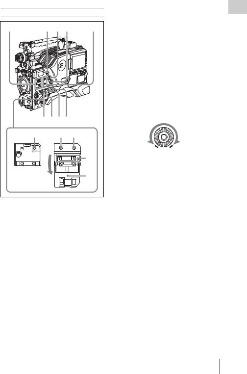
m “Memory Stick” compartment
Label
“Memory Stick” Access indicator
Open the cover of the menu operating section, and insert a “Memory Stick”, with the notch facing downward, in the direction shown by the arrow, so that it clicks into place.
To remove a “Memory Stick”, first press it in to release the lock, then withdraw.
The “Memory Stick” access indicator lights in green when a “Memory Stick” is loaded, and lights in red when the “Memory Stick” is being accessed for reading or writing.
For details about “Memory Stick”, see “Handling the “Memory Stick”” on page 230.
n Cover |
1Chapter |
|
|
|
|
Right side (near the rear) |
|
|
|
|
|
|
|
Overview |
8 |
9 |
|
q; |
qa |
||
EJECT |
F REV |
PLAY/PAUSE |
F FWD |
|||
|
|
m |
|
NX |
M |
|
Z |
|
PREV |
|
STOP |
NEXT |
|
|
|
|
||||
|
|
. |
|
x |
> |
|
|
|
qs |
|
qd |
qf |
|
|
|
|
|
|
|
1 |
|
|
|
|
|
|
2 |
|
|
|
|
|
|
3 |
|
|
|
|
|
|
4 |
|
|
|
|
|
|
5 |
|
|
|
|
|
|
6 |
|
|
|
|
|
|
7 |
qg |
qh |
qj |
|
qk |
|
ql |
DISP SEL |
HOLD |
RESET |
DISPLAY |
BRIGHT |
||
EXPAND |
CHAPTER RETURN COUNTER TC U-BIT |
|
||||
a Built-in speaker
The speaker can be used to monitor E-E sound during recording, and playback sound during playback. The speaker also sounds alarms to reinforce visual warnings.
If you connect earphones to the EARPHONE jack, the speaker output is suppressed automatically.
For details about alarms, see “Operation Warnings” on page 262.
b LCD monitor
Displays camera video, VDR-related warnings, remaining battery capacity, remaining disc capacity, audio levels, time data, and so on.
Locations and Functions of Parts and Controls 21

Overview 1 Chapter
For details, see “Status Display on the LCD monitor and monochrome LCD” on page 23.
c WARNING indicator
Lights up or flashes when an abnormality occurs in the VDR section.
For details about the meaning of the states of the WARNING indicator, see “Operation Warnings” on page 262.
d ACCESS indicator
This lights when data is written to or read from the disc.
eProtection cover of the audio control section
Open to access the audio control section (see page 27).
fProtection cover of the GUI screen operations section
Open to access the GUI screen operations section
(see page 27).
g Monochrome LCD
This shows the remaining battery capacity, remaining disc capacity, time data, and so on.
For details, see “Status Display on the LCD monitor and monochrome LCD” on page 23.
h EJECT button and indicator
Press this button to insert a disc or eject the disc. The indicator flashes while the disc is being ejected.
iF REV (fast reverse) button and indicator
This plays back at high speed in the reverse direction. The indicator lights during high-speed playback in the reverse direction.
j PLAY/PAUSE button and indicator
Press this button to view play back video images using the viewfinder screen or the LCD monitor. The indicator lights during playback.
Press this button again during playback to pause, outputting a still image. At this time the indicator flashes.
This unit is equipped with an image search function at approximately four times normal playback speed, for easy checking of recorded material. To use the image search function at
approximately four times normal playback speed, press the F REV button or F FWD button during playback.
At this time the PLAY indicator and F REV or F FWD indicator light.
kF FWD (fast forward) button and indicator
This plays back at high speed in the forward direction. The indicator lights during high-speed playback in the forward direction.
l PREV button
This jumps to the first frame of the current clip. During the jump, the F REV indicator flashes. If you press this together with the F REV button, the jump is to the first frame of the first recorded clip on the disc.
m STOP button
Press this button to stop disc playback.
n NEXT button
This jumps to the first frame of the next clip. During the jump, the F FWD indicator flashes. If you press this together with the F FWD button, the jump is to the last frame of the last recorded clip on the disc.
oDISP SEL (display selection) /EXPAND (expand function) button
With each press of this button, the display in the LCD monitor changes as follows.
Display indication |
Meaning |
Video with |
The LCD monitor displays |
superimposed |
the same text information |
information (CHAR) |
as the viewfinder. |
|
|
Video without |
The video only appears. |
superimposed |
|
information (MONI) |
|
|
|
Status display |
Counter indications, |
(STATUS) |
warnings, audio levels, and |
|
similar information appear. |
|
No video image appears. |
|
|
If you press this button when the thumbnail screen is displayed, the duration of the selected clip is divided into 12, and the first frame of each of the divisions is shown in a further thumbnail display (expand function). Each time you press this button, the division is repeated (to a maximum of three times, with 1,728 divisions).
22 Locations and Functions of Parts and Controls

Hold down the SHIFT button and press this button to step back through the division process.
For details of the expand function, see page 122.
pHOLD (display hold)/CHAPTER (chapter function) button
Pressing this button instantly freezes the time data displayed in the counter display section. (The timecode generator continues running.) Pressing this button again releases the hold.
You can use this button, for example, to determine the exact time of a particular shot.
For details of the counter display, see page 25.
If you press this button when the clip thumbnail screen is displayed, those frames on which shot marks are recorded appear in a list (chapter function). Press the button once more to return to the normal thumbnail display.
By displaying thumbnails with shot marks attached in place of index frames, you can check the contents of clips more easily and more quickly. This is also useful for cueing up long clips.
For details of the chapter function, see page 122
q RESET/RETURN button
Resets the value shown in the time counter display. According to the settings of the PRESET/ REGEN/CLOCK switch (see page 27) and the F- RUN/SET/R-RUN switch (see page 27), this button resets the display as follows.
Settings of switches |
To reset |
DISPLAY switch: |
Counter to 0:00:00:00 |
COUNTER |
|
|
|
DISPLAY switch: |
Timecode to 00:00:00:00 |
TC |
|
PRESET/REGEN/ |
|
CLOCK switch: |
|
PRESET |
|
F-RUN/SET/R-RUN |
|
switch: SET |
|
|
|
DISPLAY switch: |
User bits data a) to 00 00 00 |
U-BIT |
00 |
PRESET/REGEN/ |
|
CLOCK switch: |
|
PRESET |
|
F-RUN/SET/R-RUN |
|
switch: SET |
|
|
|
a)Of the timecode bits for every frame recorded on the disc, those bits which can be used to record useful
information for the user such as scene number, shooting place, etc.
For details, see “Setting the Time Data” on page 75.
This button returns to the previous screen when pressed during thumbnail display.
For details, see “GUI screen operations” on page 120.
r DISPLAY switch
This cycles the data displayed in the counter display through the sequence COUNTER, TC, and U-BIT.
COUNTER: Display the elapsed recording/ playback time (hours, minutes, seconds, frames).
TC: Display timecode. U-BIT: Display user bit data.
For details, see “Status Display on the LCD monitor and monochrome LCD” on page 23.
s BRIGHT (brightness) button
Switches the brightness of the LCD monitor backlight, and turns the backlight of the monochrome LCD on and off.
Each press of the button selects the next setting in the order shown in the following table.
Setting |
LCD monitor |
Monochrome |
|
backlight |
LCD backlight |
H |
High (select this to view |
Lit |
|
the LCD monitor |
|
|
outdoors in the |
|
|
daytime) |
|
|
|
|
M |
Brightness between H |
Lit |
|
and L |
|
|
|
|
L |
Low (select this to view |
Lit |
|
the LCD monitor |
|
|
indoors or outdoors at |
|
|
night) |
|
|
|
|
OFF |
Off (the display is also |
Off |
|
off) |
|
|
|
|
Status Display on the LCD monitor and monochrome LCD
The following display appears on the LCD monitor display which is set to STATUS with the DISP SEL/EXPAND button, and on the monochrome LCD.
Overview 1 Chapter
Locations and Functions of Parts and Controls 23

Overview 1 Chapter
1 2 |
3 |
4 |
5 |
|
|
|
|
|
|
O V E R |
|
HD422 |
50 |
5 9 . 9 i 2 4 b i t |
0 |
||
|
|
|||||
6 |
1080 |
P B |
N D F |
E X T - L K |
H O L D |
|
|
. . . |
|
10 |
|||
|
|
|
||||
|
|
|
|
|||
7 |
01 . |
23 . |
45 . 15 |
|
||
|
H |
M I N |
S E C |
F R M |
20 |
|
|
|
|
||||
8 |
|
W A R N I N G : H U M I D |
|
|
|
|
30 |
|
|
||||||||||||||||||
|
|
|
|
|
|
|
|||||||||||||||||||||
9 |
|
|
D I S C |
|
|
|
|
|
|
|
|
|
|
|
|
|
|
|
|
|
|
|
|
40 |
|
|
|
|
|
|
|
|
|
|
|
|
|
|
|
|
|
|
|
|
|
|
|
|
|
|
|||||
|
|
E |
|
|
|
|
|
|
|
|
|
|
|
|
|
|
|
B |
|
ST |
|
d B |
|
|
|||
|
|
|
|
|
|
|
|
|
|
|
|
|
|
|
|
|
|
|
|
|
|
|
|
||||
|
|
|
B A T T |
E |
|
|
|
|
|
|
|
|
|
|
|
|
|
|
|
F |
1 |
|
2 |
P E A K 3 4 |
|||
|
|
|
|
|
|
|
|
|
|
|
|
|
|
|
|
|
|
|
|
|
|||||||
|
|
|
|
|
|
|
|
|
|
|
|
|
|
|
|
|
|
|
|
|
|
|
|
|
|
|
|
0
LCD monitor
7


9


0
Monochrome LCD
a Resolution
Indicates the resolution of HD output video.
Indication |
Resolution (horizontal × vertical) |
1080 |
1080 lines (1920 × 1080) |
|
|
720 |
720 lines (1280 × 720) |
|
|
b Video format
Indicates the format of video being currently played back or recorded.
Indication |
Format |
Bit rate |
HD422 50 |
MPEG HD422 |
50 Mbps |
|
|
|
HD420 HQ/SP/ |
MPEG HD420 |
35/25/18 Mbps |
LP a) |
|
|
IMX 50/40/ |
MPEG IMX |
50/40/30 Mbps |
30 b) |
|
|
DVCAM b) |
DVCAM |
25 Mbps |
a)LP is playback only.
b)For the PDW-700, when the optional CBKZ-MD01 SD Record and Playback Software is installed.
c System frequency
Indicates the system frequency of video being currently played back or recorded.
If NTSC AREA is selected 1)
Indication |
Field or frame |
Scan mode |
|
rate |
|
59.9i |
59.94 fields per |
Interlace |
|
second |
|
|
|
|
59.9P |
59.94 frames per |
Progressive |
|
second |
|
|
|
|
29.9P |
29.97 frames per |
Progressive |
|
second |
|
|
|
|
23.9P a) |
23.98 frames per |
Progressive |
|
second |
|
a)For the PDW-700, when the optional CBKZ-FC02 23.98P Record and Playback Software is installed.
If PAL AREA is selected 1)
Indication |
Field or frame |
Scan mode |
|
rate |
|
50i |
50 fields per |
Interlace |
|
second |
|
|
|
|
50P |
50 frames per |
Progressive |
|
second |
|
|
|
|
25P |
25 frames per |
Progressive |
|
second |
|
|
|
|
1)Selected by COUNTRY setting on the FORMAT page of the OPERATION menu (see page 167).
Note
There may be no indication displayed when this unit cannot identify the system frequency, for example, when playing back a disc recorded with other equipment.
d Audio format
Indicates the format of audio being currently played back or recorded.
Indication |
Quantization bit rate/sampling |
|
frequency |
24bit |
24 bits/48 kHz |
|
|
16bit |
16 bits/48 kHz |
|
|
e Audio level indicators
Indicates the audio recording or playback levels of channels 1 to 4.
f Status display
PB: Appears during playback.
NDF: Appears when non-drop-frame timecode is selected.
EXT-LK: Appears when the internal timecode generator is locked to an external signal input to the TC IN (timecode input) connector.
24 Locations and Functions of Parts and Controls

HOLD: Appears when the internal timecode generator is stopped.
g Time counter display
Switches displays of time counter, timecode, and user bits, depending on the position of the DISPLAY switch.
When the HOLD/CHAPTER button is pressed to hold the timecode value, the timecode is displayed in the format shown below. When the HOLD/CHAPTER button is pressed again to release the hold, the timecode is displayed in the normal format.
Lights when the HOLD/CHAPTER button is pressed.
h Warning indicator area
Displays warnings when trouble with recording or moisture condensation occurs.
For details, see “Operation Warnings” on page 262.
Overview 1 Chapter
Locations and Functions of Parts and Controls 25

i Remaining disc capacity indicator
Chapter |
Indication |
|
Remaining recording time |
|
|
|
|||
|
DISC E [x x x x x x x] B |
More than 30 minutes |
||
|
|
|
|
|
1 |
DISC E [x x x x x x |
] B |
25 to 30 minutes |
|
|
|
|
||
Overview |
DISC E [x x x x x |
] B |
20 to 25 minutes |
|
|
|
|
||
DISC E [x x x x |
] B |
15 to 20 minutes |
||
|
||||
|
|
|
|
|
|
DISC E [x x x |
] B |
10 to 15 minutes |
|
|
|
|
|
|
|
DISC E [x x |
] B |
5 to 10 minutes |
|
|
|
|
|
|
|
DISC E [x |
] B |
2 to 5 minutes |
|
|
|
|
|
|
|
DISC E [x |
] B (flashing) |
0 to 2 minutes |
|
|
|
|
|
|
|
DISC E [ |
] B (flashing) |
0 minutes |
|
|
|
|
|
|
j Remaining battery capacity indicator
Indication |
|
Battery voltage |
|
|
|
BP-L90A/L60S/L80S |
Other batteries a) |
BATT E [x x x x x x x] F |
15.5 V or more |
17.0 V or more |
|
|
|
|
|
BATT E [x x x x x x |
] F |
15.1 to 15.5 V |
16.0 to 17.0 V |
|
|
|
|
BATT E [x x x x x |
] F |
14.6 to 15.1 V |
15.0 to 16.0 V |
|
|
|
|
BATT E [x x x x |
] F |
13.8 to 14.6 V |
14.0 to 15.0 V |
|
|
|
|
BATT E [x x x |
] F |
12.9 to 13.8 V |
13.0 to 14.0 V |
|
|
|
|
BATT E [x x |
] F |
12.0 to 12.9 V |
12.0 to 13.0 V |
|
|
|
|
BATT E [x |
] F |
10.8 to 12.0 V |
11.0 to 12.0 V |
|
|
|
|
BATT E [ |
] F |
10.8 V or less |
11.0 V or less |
|
|
|
|
a)You can change the threshold voltages on the BATTERY 2 page of the MAINTENANCE menu
(see page 182).
Indication |
|
Battery voltage |
|
|
BP-GL95/GL65/IL75/M100, Anton Bauer Battery |
|
|
System |
BATT E [x x x x x x x] F |
80 to 100% |
|
|
|
|
BATT E [x x x x x x x] |
70% |
|
|
|
|
BATT E [x x x x x x |
] |
60% |
|
|
|
BATT E [x x x x x |
] |
50% |
|
|
|
BATT E [x x x x |
] |
40% |
|
|
|
BATT E [x x x |
] |
30% |
|
|
|
BATT E [x x |
] |
20% |
|
|
|
BATT E [x |
] |
10% |
|
|
|
BATT E [ |
] |
0% |
|
|
|
26 Locations and Functions of Parts and Controls

GUI screen operations section and audio control
section |
|
|
|
|
|
|
|
1 |
2 3 4 5 |
6 |
|
||||
|
|
|
|
|
LEVEL |
|
|
|
THUMBNAIL |
|
MENU |
0 |
10 |
0 |
10 |
|
|
|
|
||||
|
|
|
|
|
|
|
CH-3 |
|
ESSENCE |
SET |
|
F-RUN |
AUTO |
|
F |
|
MARK |
|
|
SET |
|
|
R |
|
|
|
|
R-RUN |
MANUAL |
|
W |
|
|
|
|
|
AUDIO SELECT |
|
|
|
SUB CLIP |
S.SEL |
|
|
CH-1 |
CH-2 |
|
|
|
|
PRESET |
AUDIO IN |
CH-4 |
||
|
|
|
|
||||
|
|
|
|
REGEN |
FRONT |
|
F |
|
DISC MENU |
|
SHIFT |
REAR |
|
R |
|
|
|
CLOCK |
WIRELESS |
|
W |
||
7 |
8 |
|
9 0 qa |
qs |
|
||
a THUMBNAIL indicator |
|
|
|
||||
This lights when thumbnails are displayed.
bTHUMBNAIL/ESSENCE MARK button
Press this button to carry out a thumbnail search or create a clip list (see page 121).
When pressed, the whole-screen display changes to a thumbnail display. Press once more to return to the whole-screen display.
For a thumbnail search using essence marks, hold down the SHIFT button and press this button (see page 123).
cSET/S.SEL (set/scene selection) button and arrow buttons
Use these buttons to make timecode and user bit settings, and for GUI screen operations.
The arrow buttons select items and change values, and the SET/S.SEL button confirms settings. Pressing this button with thumbnails displayed and the SHIFT button held down adds a sub clip to the current clip list (scene selection).
See page 120 for more information about GUI screen operations.
See page 132 for more information about scene selection.
d MENU button
Displays a special menu for operations in GUI screens (see page 116).
When the whole-screen is displayed, pressing this button has no effect, and the operation is invalid.
eF-RUN/SET/R-RUN (free run/set/ recording run) switch
explained below, depending on the position of the |
1Chapter |
|
Selects the operating mode of the internal |
|
|
timecode generator. The operating mode is set as |
|
|
switch. |
Overview |
|
F-RUN: Timecode keeps advancing, regardless |
||
|
||
of the operating state of the VDR. Use this |
|
|
setting when synchronizing the timecode |
|
|
with an external timecode. |
|
|
SET: Sets the timecode or user bits. |
|
|
R-RUN: Timecode advances only during |
|
|
recording. Use this setting to have a |
|
|
consecutive timecode on the disc. |
|
For details, see “Setting the timecode” on page 75 and “Setting the user bits” on page 75.
fLEVEL CH-1/CH-2 (audio channel 1/2 recording level) knobs
Adjusts the audio levels to be recorded on channels 1 and 2 when the AUDIO SELECT CH- 1/CH-2 switches are set to MANUAL.
g SUB CLIP indicator
This lights when using a clip list for playback.
h SUB CLIP/DISC MENU button
Press this to play back according to a clip list. You can play back a particular clip or sequential clips, or carry out a search of the selected clip list. To display the Disc Menu which allows you to carry out operations such as saving, recalling, or deleting a clip list, hold down the SHIFT button and press this button.
i SHIFT button
Use this in combination with other buttons.
jPRESET/REGEN (regeneration)/ CLOCK switch
Selects whether to set a new timecode or to utilize the existing timecode.
PRESET: Records a new timecode.
REGEN: Records timecode continuous with the existing timecode recorded on the disc. Regardless of the setting of the F-RUN/SET/ R-RUN switch, the camcorder operates in R- RUN mode.
CLOCK: Records timecode synchronized to the internal clock. Regardless of the setting of the F-RUN/SET/R-RUN switch, the camcorder operates in F-RUN mode.
Locations and Functions of Parts and Controls 27
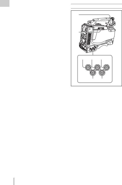
Overview 1 Chapter
28
kAUDIO SELECT CH-1/CH-2 (audio channel 1/2 adjustment method selection) switches
Select the audio level adjustment method for each of audio channels 1 and 2.
AUTO: Automatic adjustment MANUAL: Manual adjustment
lAUDIO IN CH-1/CH-2/CH-3/CH-4 (audio channel 1/2/3/4 input selection) switches
AUDIO IN CH-1/CH-2 switches
Select the audio input signals to be recorded on audio channels 1 and 2.
FRONT: Audio input signals from the microphone connected to the MIC IN connector
REAR: Audio input signals from an audio device connected to the AUDIO IN CH1/CH2 connectors
WIRELESS: Audio input signals from the UHF portable tuner (not supplied) if it is installed
AUDIO IN CH-3/CH-4 switches
Select the audio input signals to be recorded on audio channels 3 and 4.
F (FRONT): Audio input signals from a microphone connected to the MIC IN connector
R (REAR): Audio input signals from an audio device connected to the AUDIO IN CH1/ CH2 connectors
W (WIRELESS): Audio input signals from the UHF portable tuner (not supplied) if it is installed
Locations and Functions of Parts and Controls
Left side and upper section
1
2 
3 4 5
SDI IN |
GENLOCK |
|
(OPTION) |
IN |
TC IN |
TEST |
TC |
|
OUT |
OUT |
|
67
a ASSIGNABLE 3/4 switches
You can assign the desired functions to these switches on the ASSIGNABLE page of the OPERATION menu.
Nothing is assigned to these switches when the camcorder is shipped from the factory (equivalent to a selection of OFF in the menu).
For details, see “Assigning functions to ASSIGN switches” on page 221.
b Lid of the disc compartment
This opens when the EJECT button on the top panel is pressed. Press the side of the lid to close.
cSDI IN (OPTION) connector (BNC type)
This is an input connector for the optional CBKHD01 HD/SD SDI Input Board. When the CBKHD01 is installed, the unit can record HD-SDI or SD-SDI signals that are input to this connector.
dGENLOCK IN (genlock signal input) connector (BNC type)
•This connector inputs a reference signal when the camera is to be genlocked or when timecode is to be synchronized with external equipment.

Use the GENLOCK page of the MAINTENANCE menu to adjust the genlock H-phase (phase of horizontal sync signal). Available reference signals vary depending on the current system frequency as shown in the following table.
System frequency |
Available reference |
|
signals |
1080/59.94i |
1080/59.94i, 525/59.94i |
|
|
1080/50i |
1080/50i, 625/50i |
|
|
1080/29.97P |
1080/59.94i, 525/59.94i |
|
|
1080/25P |
1080/50i, 625/50i |
|
|
1080/23.98P |
1080/23.98PsF |
|
|
720/59.94P |
1080/59.94i, 525/59.94i |
|
|
720/50P |
1080/50i, 625/50i |
|
|
•This connector also inputs a return video signal. You can display the HD-Y (1080i) signal in the viewfinder screen while holding the RET button down with RETURN VIDEO set to ON on the ASSIGNABLE SW page of the OPERATION menu.
•Input an external video signal. When the optional CBK-SC02 Analog Composite Input Board is installed, the unit can record analog composite video signals that are input to this connector.
eTC IN (timecode input) connector (BNC type)
To apply an external lock to the timecode of this unit, input the reference timecode.
For details of timecode, see “Setting the timecode” on page 75.
f TEST OUT connector (BNC type)
This connector outputs the video signal for a video monitor. The output signal can be selected from composite video, HD-Y, R, G, B, and a composite video signal like that displayed in the LCD monitor. To switch output signals, use the TEST OUT SELECT item on the OUTPUT 1 page of the OPERATION menu.
If the output signal is set to one of R, G, or B, then this setting changes to HD-Y when the camcorder is powered off and on again.
Depending on menu settings, menus, timecode, and shot data can be superimposed on the image on the monitor. This connector can also be used to synchronize the timecode of an external VTR with the timecode of the camcorder.
gTC OUT (timecode output) connector (BNC type)
To lock the timecode of an external VTR to the timecode of this unit, connect this connector to the external VTR’s timecode input connector.
Rear |
|
|
|
|
|
|
|
|
|
|
|
|
1 |
|
|
|
|
|
|
2 |
|
|
|
|
|
|
3 |
|
|
|
|
|
|
4 |
5 |
6 |
|
|
7 |
|
|
|
AES/EBU |
AUDIO IN |
AES/EBU |
|
|
|
|
LINE |
MIC |
LINE |
MIC |
|
|
|
|
48V |
|
48V |
|
|
|
DC OUT |
OFF |
|
OFF |
AUDIO OUT |
|
|
12V |
|
|
|
|
|
DC |
0.5A |
|
|
|
|
|
IN |
|
|
|
|
|
|
|
SUPER |
|
|
|
|
|
|
CH1 |
|
CH2 |
|
|
|
|
1/2 |
|
3/4 |
|
|
|
SDI OUT |
SDI OUT |
|
|
|
|
|
8 9 0 |
|
qa |
|
qs |
qd |
|
a TALLY (back tally) indicator (red) |
||||||
Lights up during recording. It will not light if the TALLY switch is set to OFF. This indicator also flashes to indicate warnings (see page 22) in the same manner as the REC/TALLY indicator in the viewfinder.
For details, see “Operation Warnings” on page 262.
b TALLY switch
Set to ON to activate the TALLY indicator function.
c USB connector
This is a USB 2.0 connector.
Connect one of the following devices, depending on what you want to do.
Overview 1 Chapter
Locations and Functions of Parts and Controls 29

Overview 1 Chapter
Device |
Enables |
Windows USB |
Text input wth the on-screen |
keyboard or mouse |
software keyboard (see page |
|
128) |
|
|
USB flash drive |
Recording of proxy data (see |
|
page 107) |
|
|
|
Loading of planning metadata |
|
(see page 140) |
|
|
Optional CBK- |
Making wireless LAN |
WA01 Wi-Fi |
connections (see page 224) |
adapter |
|
|
|
Before using this connector, you must set ETHERNET/USB on the POWER SAVE page of the OPERATION menu to “ENABL” (see page 224).
d  (network) connector (RJ-45 type)
This is a 10BASE-T/100BASE-TX connector for network connection.
Before using this connector, you must set ETHERNET/USB on the POWER SAVE page of the OPERATION menu to “ENABL” (see page 224).
CAUTION
For safety, do not connect the connector for peripheral device wiring that might have excessive voltage to this port. Follow the instructions for this port.
When you connect the network cable of the unit to peripheral device, use a shielded-type cable to prevent malfunction due to radiation noise.
e EARPHONE jack (stereo, minijack)
You can monitor the E-E sound during recording and playback sound during playback. When an alarm is indicated, you can hear the alarm sound through the earphone. You can use this with the EARPHONE jack on the front of the unit at the same time. Plugging an earphone into the jack automatically cuts off the built-in speaker.
You can select monaural or stereo on the AUDIO- 1 page of the MAINTENANCE menu.
f LINE / AES/EBU / MIC selectors
These select the audio source of the audio input signals input to the AUDIO IN CH1/CH2 connectors.
LINE: Line input audio equipment AES/EBU: AES/EBU format audio signal MIC: Microphone input
Note
When these switches are in the MIC position, and the +48V/OFF switch is set to +48V, if you inadvertently connect any audio device other than a microphone to the AUDIO IN CH1/CH2 connectors, the device may be damaged.
g +48V/OFF switches
Select either of the following positions for the microphones to be connected.
+48V: For a microphone to use an external power supply
OFF: For a microphone to use an internal power supply
h REMOTE connector (8-pin)
Connect an RM-B150/B750 remote control unit, which makes it possible to control the camcorder remotely.
Note
Before connecting/disconnecting the Remote Control Unit to/from the camcorder, be sure to turn off the camcorder POWER switch.
i SDI OUT 1 connector (BNC type)
Outputs an HDSDI or SDSDI signal (with embedded audio). To switch between HDSDI and SDSDI output, use the SDI OUT 1 SELECT item on the OUTPUT 1 page of the OPERATION menu.
j SDI OUT 2 connector (BNC type)
Outputs an HDSDI or SDSDI signal (with embedded audio). To switch between HDSDI and SDSDI output, use the SDI OUT 2 SELECT item on the OUTPUT 1 page of the OPERATION menu.
Setting menus, timecode, or shot data can be superimposed on the camera output video depending on the menu settings, and you can view them on the monitor screen.
kAUDIO IN CH1/CH2 (audio channel-1 and channel-2 input) connectors (XLR type, 3-pin, female)
These are audio input connectors for channels 1 and 2 to which you can connect audio equipment or a microphone.
When the LINE / AES/EBU / MIC selector is set to AES/EBU, the CH1 connector is used for channel-1 and -2 inputs, and the CH2 connector, for channel-3 and -4 inputs.
30 Locations and Functions of Parts and Controls
 Loading...