


PDW-1500

PROFESSIONAL DISC RECORDER
PDW-1500
OPERATION MANUAL [English]
1st Edition (Revised 1)
WARNING
To prevent fire or shock hazard, do not
expose the unit to rain or moisture.
To avoid electrical shock, do not open the
cabinet. Refer servicing to qualified
personnel only.
THIS APPARATUS MUST BE EARTHED.
CAUTION
The apparatus shall not be exposed to dripping or splashing
and no objects filled with liquid, such as vases, shall be placed
on the apparatus.
The unit is not disconnected from the AC power source
(mains) as long as it is connected to the wall outlet, even if the
unit itself has been turned off.
Do not install the appliance in a confined space, such as a
book case or built-in cabinet.
If used in USA, use the UL LISTED power cord specified
below.
DO NOT USE ANY OTHER POWER CORD.
Plug Cap Parallel blade with ground pin
(NEMA 5-15P Configuration)
Cord Type SJT, three 16 or 18 AWG wires
Length Minimum 1.5 m, Less than 2.5 m (8 ft 3 in)
Rating Minimum 10 A, 125 V
Using this unit at a voltage other than 120 V may require the
use of a different line cord or attachment plug, or both. To
reduce the risk of fire or electric shock, refer servicing to
qualified service personnel.
WARNING: THIS WARNING IS APPLICABLE FOR OTHER
COUNTRIES.
1. Use the approved Power Cord (3-core mains lead)/
Appliance Connector/Plug with earthing-contacts that
conforms to the safety regulations of each country if
applicable.
2. Use the Power Cord (3-core mains lead)/Appliance
Connector/Plug conforming to the proper ratings (Voltage,
Ampere).
This apparatus is provided with a main switch on the rear
panel. Install this apparatus so that user can access the main
switch easily.
This symbol is intended to alert the user to
the presence of uninsulated “dangerous
voltage” within the product’s enclosure that
may be of sufficient magnitude to constitute
a risk of electric shock to persons.
This symbol is intended to alert the user to
the presence of important operating and
maintenance (servicing) instructions in the
literature accompanying the appliance.
WARNING: THIS WARNING IS APPLICABLE FOR USA
ONLY.
If you have questions on the use of the above Power Cord/
Appliance Connector/Plug, please consult a qualified service
personnel.
This Professional Disc Recorder is classified as a CLASS 1
LASER PRODUCT.
Laser diode properties
Wavelength: 403 to 410 nm
Emission duration: Continuous
Laser output power: 65 mW (max. of pulse peak), 35 mW
(max. of CW)
Tekniska data för laserdiod
Våglängd: 403 till 410 nm
Emissionslängd: Kontinuerlig
Laseruteffekt: 65 mW (max. för pulstopp), 35 mW (max. för
kontinuerlig våg)
Spesifikasjoner laserdiode
Bølgelengde: 403 til 410 nm
Strålingens varighet: Kontinuerlig
Laserens effekt: 65 mW (maks stråletoppunkt), 35 mW
(maks ved kontinuerlig stråling)
Laserdiodin ominaisuudet
Aallon pituus: 403 - 410 nm
Välityksen kesto: Jatkuva
Laserlähdön teho: 65 mW (sykehuipun maks.), 35 mW
(jatkuvan aallon maks.)
2
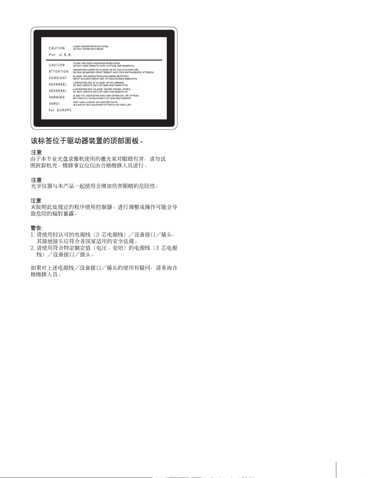
This label is located on the top panel of the
drive unit.
CAUTION
As the laser beam used in this Professional Disc Recorder is
harmful to the eyes, do not attempt to disassemble the
cabinet. Refer servicing to qualified personnel only.
CAUTION
The use of optical instruments with this product will increase
eye hazard.
CAUTION
Use of controls or adjustments or performance of procedures
other than those specified herein may result in hazardous
radiation exposure.
VAROITUS!
LAITTEEN KÄYTTÄMINEN MUULLA KUIN TÄSSÄ
KÄYTTÖOHJEESSA MAINITULLA TAVALLA SAATTAA
ALTISTAA KÄYTTÄJÄN TURVALLISUUSLUOKAN 1
YLITTÄVÄLLE NÄKYMÄTTÖMÄLLE LASERSÄTEILYLLE.
VARNING
OM APPARATEN ANVÄNDS PÅ ANNAT SÄTT ÄN I DENNA
BRUKSANVISNING SPECIFICERATS, KAN ANVÄNDAREN
UTSÄTTAS FÖR OSYNLIG LASERSTRÅLNING, SOM
ÖVERSKRIDER GRÄNSEN FÖR LASERKLASS 1.
Important Safety Instructions
• Read these instructions.
• Keep these instructions.
• Heed all warnings.
• Follow all instructions.
• Do not use this apparatus near water.
• Clean only with dry cloth.
• Do not block any ventilation openings.
Install in accordance with the manufacturer’s instructions.
• Do not install near any heat sources such as radiators, heat
registers, stoves, or other apparatus (including amplifiers)
that produce heat.
• Do not defeat the safety purpose of the polarized or
grounding-type plug. A polarized plug has two blades with
one wider than the other. A grounding-type plug has two
blades and a third grounding prong. The wide blade or the
third prong are provided for your safety. If the provided plug
dose not fit into your outlet, consult an electrician for
replacement of the obsolete outlet.
• Protect the power cord from being walked on or pinched
particularly at plugs, convenience receptacles, and the point
where they exit from the apparatus.
• Only use attachments/accessories specified by the
manufacturer.
• Use only with the cart, stand, tripod, bracket, or table
specified by the manufacturer, or sold with the apparatus.
When a cart is used, use caution when moving the cart/
apparatus combination to avoid injury from tip-over.
• Unplug this apparatus during lightning storms or when
unused for long periods of time.
• Refer all servicing to qualified service personnel. Servicing
is required when the apparatus has been damaged in any
way, such as power-supply cord or plug is damaged, liquid
has been spilled or objects have fallen into the apparatus,
the apparatus has been exposed to rain or moisture, does
not operate normally, or has been dropped.
For the customers in the USA
This equipment has been tested and found to comply with the
limits for a Class A digital device, pursuant to Part 15 of the
FCC Rules. These limits are designed to provide reasonable
protection against harmful interference when the equipment is
operated in a commercial environment. This equipment
generates, uses, and can radiate radio frequency energy and,
if not installed and used in accordance with the instruction
manual, may cause harmful interference to radio
communications. Operation of this equipment in a residential
area is likely to cause harmful interference in which case the
user will be required to correct the interference at his own
expense.
You are cautioned that any changes or modifications not
expressly approved in this manual could void your authority to
operate this equipment.
The shielded interface cable recommended in this manual
must be used with this equipment in order to comply with the
limits for a digital device pursuant to Subpart B of Part 15 of
FCC Rules.
3
For the customers in Europe
This product with the CE marking complies with both the EMC
Directive (89/336/EEC) and the Low Voltage Directive (73/23/
EEC) issued by the Commission of the European Community.
Compliance with these directives implies conformity to the
following European standards:
• EN60065: Product Safety
• EN55103-1: Electromagnetic Interference (Emission)
• EN55103-2: Electromagnetic Susceptibility (Immunity)
This product is intended for use in the following
Electromagnetic Environment(s):
E1 (residential), E2 (commercial and light industrial), E3
(urban outdoors) and E4 (controlled EMC environment, ex. TV
studio).
Voor de Klanten in Nederland
• Dit apparaat bevat een vast ingebouwde batterij die niet
vervangen hoeft te worden tijdens de levensduur van het
apparaat.
• Raadpleeg uw leverancier indien de batterij toch vervangen
moet worden.
De batterij mag alleen vervangen worden door vakbekwaam
servicepersoneel.
• Gooi de batterij niet weg maar lever deze in als klein
chemisch afval (KCA).
• Lever het apparaat aan het einde van de levensduur in voor
recycling, de batterij zal dan op correcte wijze verwerkt
worden.
AVERTISSEMENT
Afin d’éviter tout risque d’incendie ou
d’électrocution, ne pas exposer l’appareil à
la pluie ou à l’humidité.
Afin d’écarter tout risque d’électrocution,
garder le coffret fermé. Ne confier
l’entretien de l’appareil qu’à un personnel
qualifié.
CET APPAREIL DOIT ÊTRE RELIÉ À LA
TERRE.
ATTENTION
Eviter d’exposer l’appareil à un égouttement ou à des
éclaboussures et ne placer aucun objet rempli de liquide,
comme un vase, sur l’appareil.
Cet appareil n’est pas déconnecté de la source d’alimentation
secteur tant qu’il est raccordé à la prise murale, même si
l’appareil lui-même a été mis hors tension.
For Customers in Taiwan only
Ne pas installer l’appareil dans un endroit confiné, par
exemple une bibliothèque ou un placard encastré.
Cet appareil possède son interrupteur principal sur le panneau
arrière. Installer l’appareil de façon que l’utilisateur puisse
accéder facilement à l’interrupteur principal.
Avant d’utiliser un câble à fiche modulaire :
Par mesure de sécurité, ne pas raccorder à un connecteur
pour câblage de périphérique qui pourrait avoir une tension
excessive.
Cet enregistreur de disques pour professionnels est classé
PRODUIT LASER DE CLASSE 1.
Propriétés de la diode laser
Longueur d’onde : 403 à 410 nm
Durée d’émission : Continue
Puissance de sortie laser : 65 mW (maxi de crête
d’impulsion), 35 mW (maxi d’ondes entretenues)
4

Cette étiquette est placée sur le panneau
supérieur de l’unité de commande.
ATTENTION
Comme le rayon laser utilisé dans cet Enregistreur de disques
pour professionnels est dangereux pour les yeux, ne pas
essayer de démonter le coffret. Faire effectuer l’entretien
uniquement par un personnel qualifié.
ATTENTION
L’emploi d’instruments optiques avec ce produit augmentera
les risques pour les yeux.
AVERTISSEMENT :
1. Utilisez un câble d’alimentation (cordon secteur trifilaire),
un connecteur d’appareil ménager et une fiche avec mise à
la terre homologués selon la réglementation de votre pays,
le cas échéant.
2. Utilisez un câble d’alimentation (cordon secteur trifilaire),
un connecteur d’appareil ménager et une fiche dont la
capacité en tension (V) et en intensité électrique (A)
convient à cet appareil.
Pour toute question au sujet de l’utilisation du câble
d’alimentation, du connecteur d’appreil ménager ou de la fiche
mentionnés ci-dessus, consultez un réparateur qualifié.
ATTENTION
L’emploi de commandes ou ajustements ou l’exécution de
procédures autres que celles spécifiées ici peut provoquer
une exposition dangereuse au rayonnement.
Pour les clients européens
Ce produit portant la marque CE est conforme à la fois à la
Directive sur la compatibilité électromagnétique (EMC) (89/
336/CEE) et à la Directive sur les basses tensions
(73/23/CEE) émises par la Commission de la Communauté
européenne.
La conformité à ces directives implique la conformité aux
normes européennes suivantes :
• EN60065 : Sécurité des produits
• EN55103-1 : Interférences électromagnétiques (émission)
• EN55103-2 : Sensibilité électromagnétique (immunité)
Ce produit est prévu pour être utilisé dans les environnements
électromagnétiques suivants :
E1 (résidentiel), E2 (commercial et industrie légère),
E3 (urbain extérieur) et E4 (environnement EMC contrôlé ex.
studio de télévision).
5
WARNUNG
Um Feuergefahr und die Gefahr eines
elektrischen Schlages zu vermeiden, darf
das Gerät weder Regen noch Feuchtigkeit
ausgesetzt werden.
Um einen elektrischen Schlag zu
vermeiden, darf das Gehäuse nicht
geöffnet werden. Überlassen Sie
Wartungsarbeiten stets nur qualifiziertem
Fachpersonal.
DIESES GERÄT MUSS GEERDET
WERDEN.
ACHTUNG
Das Gerät ist nicht tropf- und spritzwassersicher, daher
dürfen keine mit Flüssigkeiten gefüllten Gegenstände, z. B.
Vasen, darauf abgestellt werden.
Solange das Netzkabel an eine Netzsteckdose
angeschlossen ist, bleibt das Gerät auch im ausgeschalteten
Zustand mit dem Stromnetz verbunden.
Das Gerät nicht an Orten aufstellen, z.B. in Bücherregalen
oder Einbauschränken, wo keine ausreichende Belüftung
gewährleistet ist.
Der Hauptschalter dieses Geräts befindet sich an der
Rückwand. Stellen Sie das Gerät so auf, dass jederzeitiger
Zugriff auf diesen Hauptschalter gewährleistet ist.
Bei Verwendung eines Kabels mit RJ-11-Stecker:
Aus Sicherheitsgründen nicht mit einer Komponente
verbinden, die u.U. eine übermäßig hohe Spannung führt.
Dieser Professional Disc Recorder ist als CLASS 1 LASER
PRODUCT eingestuft.
Eigenschaften der Laserdiode
Wellenlänge: 403 bis 410 nm
Emissionsdauer. Ununterbrochen
Laser-Ausgangsleistung: 65 mW (max. Impulsspitze), 35
mW (max. Dauerstrich)
Dieser Aufkleber befindet sich oben auf der
Antriebseinheit.
VORSICHT
Die Laserstrahlung im Innern ist augenschädlich. Deshalb den
Professional Disc Recorder nicht öffnen/zerlegen.
Wartungsarbeiten ausschließlich qualifiziertem Fachpersonal
überlassen.
VORSICHT
Der Einsatz von optischen Hilfen verstärkt die Gefahr von
Augenschäden.
VORSICHT
Bei Betätigung von Bedien- und Einstellteilen oder
Ausführung von Bedienvorgängen, die nicht ausdrücklich in
dieser Bedienungsanleitung aufgeführt sind, droht u.U. die
Einwirkung gefährlicher Laserstrahlung.
GEFAHR
Bei geöffnetem Laufwerk und beschädigter oder deaktivierter
Verriegelung tritt ein unsichtbarer Laserstrahl aus.
Direkter Kontark mit dem Laserstrahl ist unbedingt zu
vermeiden.
Für Kunden in Europa
Dieses Produkt besitzt die CE-Kennzeichnung und erfüllt die
EMV-Richtlinie (89/336/EWG) sowie die
Niederspannungsrichtlinie (73/23/EWG) der EG-Kommission.
Angewandte Normen:
• EN60065: Sicherheitsbestimmungen
• EN55103-1: Elektromagnetische Verträglichkeit
(Störaussendung)
• EN55103-2: Elektromagnetische Verträglichkeit
(Störfestigkeit),
für die folgenden elektromagnetischen Umgebungen: E1
(Wohnbereich), E2 (kommerzieller und in beschränktem
Maße industrieller Bereich), E3 (Stadtbereich im Freien) und
E4 (kontrollierter EMV-Bereich, z.B. Fernsehstudio)
6

1. Für Ihren privat genutzten Videorecorder muß eine
Fernseh-Rundfunk-Genehmigung beantragt werden,
sofern nicht bereits eine Genehmigung für ein
Fernsehgerät desselben Haushaltes vorliegt. Im
geschäftlichen Bereich ist jeder einzelne
Videorecorder anmelde- und gebührenpflichtig.
(Auskunft ggf. bei der GEZ oder den
Rundfunkanstalten.)
2. Im privaten Bereich ist die Aufzeichnung von
urheberrechtlich geschützten Werken auf Bild- und
Tonträger gestattet. Die entsprechenden UrheberVergütungen sind im Kaufpreis des Gerätes
enthalten. Öffentliche Wiedergabe oder Verbreitung
von mitgeschnittenen Fernsehsendungen ist ohne
Erlaubnis nicht zulässig, verpflichtet zu
Schadenersatz und ist gegebenenfalls strafbar.
ATTENZIONE
Per evitare il pericolo di incendi o scosse
elettriche, non esporre l’apparecchio alla
pioggia o all’umidità.
Per evitare scosse elettriche, non aprire
l’apparecchio.
Per le riparazioni, rivolgersi solo a
personale qualificato.
QUESTO APPARECCHIO DEVE ESSERE
MESSO A TERRA.
3. Im Rahmen der Regelung des §47 des
Urheberrechtsgesetzes sind Aufzeichnungen von
Schulfernsehprogrammen gestattet. Mitschnitte von
Schulfunksendungen dürfen jedoch nur für den
Unterricht verwendet werden und sind spätestens am
Ende des laufenden Schuljahres zu löschen.
ACHTUNG:
1. Verwenden Sie ein geprüftes Netzkabel (3-adriges
Stromkabel)/einen geprüften Geräteanschluss/einen
geprüften Stecker mit Schutzkontakten entsprechend den
Sicherheitsvorschriften, die im betreffenden Land gelten.
2. Verwenden Sie ein Netzkabel (3-adriges Stromkabel)/
einen Geräteanschluss/einen Stecker mit den geeigneten
Anschlusswerten (Volt, Ampere).
Wenn Sie Fragen zur Verwendung von Netzkabel/
Geräteanschluss/Stecker haben, wenden Sie sich bitte an
qualifiziertes Kundendienstpersonal.
Zum Netzanschluß dieses Gerätes ist eine geprüfte Leitung zu
verwenden. Es sind die zutreffenden nationalen Errichtungsund/oder Gerätebestimmungen zu beachten.
(Für einen Nennstrom bis 6A)
Es ist eine geprüfte flexible PVC-ummantelte Leitung
entsprechend IEC 60227 (H05VV-F 3G 0.75 mm2 oder
H05VVH2-F 3G 0.75 mm2) zu verwenden.
Andernfalls ist eine flexible Leitung aus systhetischem Gummi
entsprechend IEC 60245 (Bauartkurzzeichen H05RR-F 3G
0.75 mm2) zu verwenden.
ATTENZIONE
L’apparecchio non deve essere esposto a gocciolamenti o
spruzzi. Non collocare sull’apparecchio oggetti contenenti
liquidi, come ad esempio vasi di fiori.
L’apparecchio non è scollegato dalla fonte di alimentazione
CA (corrente di rete) fintanto che è collegato ad una presa di
corrente, anche se l’apparecchio stesso è stato spento.
Evitate di installare l’apparecchio in uno spazio limitato, tipo in
una libreria o in un mobiletto incassato.
Questo apparecchio è provvisto di interruttore principale
posizionato sul pannello posteriore. Installare l’apparecchio in
modo tale che l’utente possa accedere facilmente
all’interruttore principale.
Quando si usa un cavo a presa modulare
Per sicureazza non collegare ad un connettore per il
collegamento di periferiche, che potrebbe avere una tensione
eccessiva.
Questo registratore di dischi professionale è classificato come
PRODOTTO LASER CLASSE 1.
Proprietà del laser a diodo
Lunghezza d’onda: da 403 a 410 nm
Durata emissione: Continua
Potenza d’emissione del laser: 65 mW (mass. a picco di
impulso), 35 mW (mass. di CW)
7

Questa etichetta si trova sul pannello
superiore dell’unità di pilotaggio.
CAUTELA
Poiché il raggio laser impiegato in questo registratore di dischi
professionale è dannoso alla vista, non tentare di smontare il
rivestimento. Per la manutenzione rivolgersi esclusivamente a
personale qualificato.
CAUTELA
L’uso di strumenti ottici con questo prodotto aumenta il rischio
per la vista.
ATTENZIONE:
1. Utilizzare un cavo di alimentazione (a 3 anime)/
connettore per l’apparecchio/spina con terminali di messa a
terra approvati che siano conformi alle normative sulla
sicurezza in vigore in ogni paese, se applicabili.
2. Utilizzare un cavo di alimentazione (a 3 anime)/
connettore per l’apparecchio/spina confrmi alla rete
elettrica (voltaggio, ampere).
In caso di domande relative all’uso del cavo di alimentazione/
connettore per l’apparecchio/spina di cui sopra, consultare
personale qualificato.
CAUTELA
L’uso di comandi o regolazioni o l’esecuzione di procedimenti
diversi da quelli specificati in questo manuale possono
causare esposizione a radiazioni pericolose.
Per i clienti in Europa
Questo prodotto recante il marchio CE è conforme sia alla
direttiva sulla compatibilità elettromagnetica (EMC) (89/336/
CEE) che alla direttiva sulle basse tensioni (73/23/CEE)
emesse dalla Commissione della Comunità Europea.
La conformità a queste direttive implica la conformità alle
seguenti normative europee:
• EN60065: Sicurezza dei prodotti
• EN55103-1: Interferenza elettromagnetica (Emissione)
• EN55103-2: Sensibilità ai disturbi elettromagnetici
(Immunità)
Questo prodotto è destinato all’uso nei seguenti ambienti
elettromagnetici:
E1 (residenziali), E2 (commerciali e industriali leggeri), E3
(esterni urbani) e E4 (ambienti EMC controllati, ad esempio
studi televisivi).
8
ADVERTENCIA
Para evitar el riesgo de incendios o
electrocución, no exponga la unidad a la
lluvia ni a la humedad.
Para evitar descargas eléctricas, no abra el
aparato. Solicite asistencia técnica
únicamente a personal especializado.
ESTE APARATO DEBE CONECTARSE A
TIERRA.
PRECAUCIÓN
No se debe exponer la unidad a derrames ni goteos, ni se
debe situar cerca objetos llenos de líquido, como por ejemplo
vasos.
La unidad no queda desconectada de la alimentación
eléctrica siempre que esté conectado al tomacorriente incluso
aunque se desconecte el interruptor principal.
No instale el aparato en un lugar estrecho como en una
biblioteca o mueble integrado.
Este aparato tiene el interruptor principal en el panel trasero.
Instale este aparato de tal forma que pueda utilizar fácilmente
el interruptor principal.
Cuando utilice un cable con clavija modular:
Por motivos de seguridad, no conecte a ningún conector para
dispositivos periféricos que puedan utilizar tensión excesiva.
Este grabador de discos profesional está clasificado como
CLASS 1 LASER PRODUCT.
Esta etiqueta se encuentra en el panel
superior de la unidad de mando.
CAUTION
Como el rayo láser utilizado en este grabador de discos
profesional es peligroso para los ojos, no trate de desarmar la
caja. Solicite el servicio sólo al personal cualificado.
CAUTION
El uso de instrumentos ópticos con este producto aumentará
el peligro a los ojos.
CAUTION
La utilización de controles o ajustes, o la realización de
procedimientos no especificados aquí pueden resultar en la
exposición a radiación peligrosa.
Para los clientes de Europa
Este producto cumple con las directivas de compatibilidad
electromagnética (89/336/CEE) y baja tensión (73/23/CEE)
de la Comisión Europea.
El cumplimiento de estas directivas implica la conformidad
con los siguientes estándares europeos:
• EN60065: Seguridad del producto
• EN55103-1: Interferencia electromagnética (Emisión)
• EN55103-2: Susceptibilidad electromagnética (Inmunidad)
Este producto está ha sido diseñado para utilizarse en los
entornos electromagnéticos siguientes:
E1 (zona residencial), E2 (zona comercial e industrial ligera),
E3 (exteriores urbanos), y E4 (entorno con EMC controlada,
p. ej., estudio de televisión).
Propiedades del diodo láser
Longitud de onda: 403 a 410 nm
Duración de la emisión: Continua
Potencia de salida láser: 65 mW (máx. de pico de pulso),
35 mW (máx. de onda continua)
9
ADVERTENCIA:
1. Utilice el cable de alimentación (3 conductores
eléctricos), el conector de dispositivos y el enchufe con
contactos de puesta a tierra aprobados que cumplen con
las normas de seguridad de cada país, si existen.
2. Utilice el cable de alimentación (3 conductores
eléctricos), el conector de dispositivos y el enchufe que
cumplen los valores nominales adecuados (voltaje,
amperios).
Si tiene alguna pregunta acerca del uso del cable de
alimentación, el conector de dispositivos o el enchufe,
póngase en contacto con el personal de servicio cualificado.
10
11

Table of Contents
Before Using the Unit ............................ 14
Setting the Line Mode ..............................14
Chapter 1 Overview
1-1 Features............................................. 16
1-2 Using the CD-ROM Manual .............. 18
1-2-1 CD-ROM System Requirements ..... 18
1-2-2 Preparations ..................................... 18
1-2-3 Reading the CD-ROM Manual........ 18
Chapter 2 Names and Functions of
Parts
2-1 Front Panel ........................................ 19
2-2 Rear Panel ......................................... 27
Chapter 3 Preparations
3-1 Connections and Settings................ 31
3-1-1 Connecting an External Monitor .....31
3-1-2 Connections for Using PDZ-1 Proxy
Browsing Software ..........................32
3-1-3 Connecting to a Nonlinear Editing
System.............................................. 34
3-1-4 Connections for Cut Editing ............35
3-1-5 Connections for Clip Audio Insert
Editing.............................................. 37
3-1-6 Editing Control Unit Settings ..........41
3-2 Setup.................................................. 42
3-3 Setting the Date and Time................ 42
3-4 Superimposed Text Information...... 43
3-5 Handling Discs.................................. 45
3-5-1 Discs Used for Recording and Playback
45
3-5-2 Notes on Handling ...........................45
3-5-3 Write-Protecting Discs ....................45
3-5-4 Loading and Unloading a Disc ........46
3-5-5 Formatting a Disc ............................46
3-5-6 To Eject Discs With the Unit Powered
Off .................................................... 47
3-5-7 Handling of Discs When Recording
Does Not End Normally (Salvage
Function).......................................... 47
Chapter 4 Recording/Playback
4-1 Recording .......................................... 48
4-1-1 Preparations for Recording ..............48
4-1-2 Recording Time Code and User Bit
Values ..............................................50
4-1-3 Recording Operation........................ 53
4-1-4 Auto Clip List Recording for Automatic
Inclusion of Recorded Clips in Clip Lists
54
4-2 Playback ............................................ 55
4-2-1 Preparations for Playback ................55
4-2-2 Playback Operation.......................... 56
4-2-3 Thumbnail Search............................ 58
4-2-4 Clip List Playback............................60
Chapter 5 Scene Selection
5-1 Overview............................................ 61
5-2 Basic Operations .............................. 62
5-2-1 Creating Clip Lists........................... 62
5-2-2 Editing Clip Lists.............................64
5-3 Clip List Operations.......................... 67
5-3-1 Displaying the CLIP Menu.............. 67
5-3-2 Saving the Current Clip List to Disc67
5-3-3 Loading a Clip List From Disc Into the
Current Clip List ..............................68
5-3-4 Deleting Clip Lists From Disc.........68
5-3-5 Clearing the Current Clip List .........69
5-3-6 Setting the Start Timecode of the
Current Clip List ..............................69
5-4 Using PDZ-1 Proxy Browsing Software
70
Chapter 6 Insert Editing
6-1 Clip Audio Insert Editing.................. 71
6-1-1 Preparations for Editing................... 71
6-1-2 Editing Operations........................... 72
Chapter 7 File Operations
7-1 Overview............................................ 74
7-1-1 Directory Structure .......................... 74
7-1-2 File Operation Restrictions ..............75
7-2 File Access Mode File Operations... 77
7-3 FTP File Operations.......................... 78
7-3-1 Command List .................................80
12
Table of Contents

Chapter 8 Menus
8-1 Menu System Configuration ............ 85
8-2 Basic Setup Menu.............................86
8-2-1 Items in the Basic Setup Menu ........86
8-2-2 Basic Menu Operations ...................88
8-3 Extended Menu ................................. 92
8-3-1 Items in the Extended Menu ............ 92
8-3-2 Extended Menu Operations ...........102
8-3-3 Using UMID Data ......................... 104
8-4 Maintenance Menu.......................... 106
8-4-1 Items in the Maintenance Menu ....106
8-4-2 Maintenance Menu Operations...... 108
8-5 System Menu................................... 111
8-5-1 Items in the System Menu ............. 111
8-5-2 System Menu Operations............... 111
Chapter 9 Maintenance and
Troubleshooting
9-1 Periodic Maintenance..................... 113
9-1-1 Digital Hours Meter....................... 113
9-2 Error Messages............................... 114
9-3 Alarms.............................................. 115
9-3-1 Alarm List...................................... 115
Appendix
Specifications........................................ 124
Glossary................................................. 127
Index....................................................... 129
Table of Contents
13
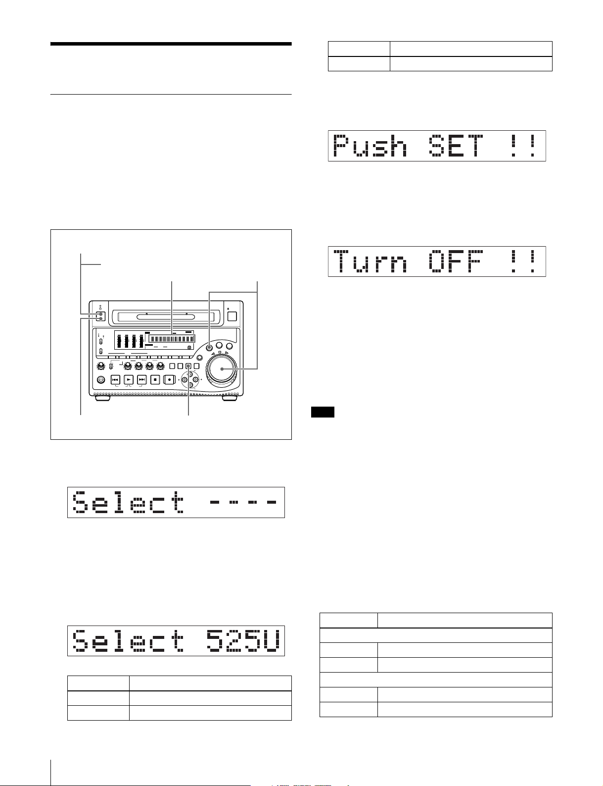
Before Using the Unit
Setting the Line Mode
This unit is shipped with the line mode still unset.
Therefore you need to set the line mode before using the
unit. (The unit cannot be used unless the line mode is set.)
Once it is set, the line mode is retained even when the unit
is powered off.
Setting procedure
Use the following procedure to set the line mode.
1
POWER switch (rear panel)
ACCESS
MONITOR
PHONES
NETWORK
LOCAL
REMOTE
L
MIX
R
SGDATA
SGDATA
ANASDI
ANASDI
AE8/EBU
AE8/EBU
dB
dB
OVER
OVER
0
0
-12
-12
-20
-20
-30
-30
-40
-40
-60
-60
CH
- 15
CH
- 26
AUDIO
MONITOR SEL
METER SEL INPUT CH INPUT SEL
ALL/CH-1 CH-2 CH-3 CH-4
VARIABLE
REC
PRESET
PB
PLAY
PREV
TOP
F REV F FWD
Time data display
SGDATA
SGDATA
EDIT KEY INHREMOTE [9P iLINK
ANASDI
ANASDI
INPUT
AE8/EBU
AE8/EBU
VITC VITCCOUNTER RECINHVIUB
i.LINK
dB
dB
OVER
OVER
0
0
SDI
CMPST
-12
-12
Y-R,B
-20
-20
SG
HOURS MINUTES SECONDS FRAMES
-30
-30
-40
-40
MONITOR
-60
-60
1/2
3/4
AUDIO
CH
- 37
CH
- 48
18 24 BIT
5/6
7/8
4 8 CH
VIDEO
COUNTER
INPUT SEL
SELECT
NEXT
STOP
END
]
625
IMX[50 40 30
DVCAM
525
HOLD
SUB
CLIP
CLIP
MENU
REC
ALARM
]
SYS MENU
MENU
THUMB
SET RESET
NAIL
ESSENCE
S.SEL
MARK1
MARK
IN OUT
MARK2
E
L
T
T
U
H
S
SHIFT
2,3
EJECT
G
O
J
V
A
R
Setting Line mode
625 625: PAL
3
When the desired setting appears, release the
SHUTTLE button.
“Push SET !!” appears.
To redo the selection
Repeat step 2.
4
Press the SET button.
“Turn OFF !!” appears.
5
Power the unit off, and then power it on again.
The selected line mode becomes available for use.
You can change the setting made with this procedure
by using basic menu item 013 “525/625 SYSTEM
SELECT.” See 8-2-2 “Basic Menu Operations” (page
88) for more information about how to make basic
menu settings.
45
1
Power the unit on.
“Select ----” appears in the time data display.
2
With the SHUTTLE button held down, rotate the jog
dial.
When you rotate the jog dial in the forward direction,
the “----” part of the display changes in the sequence
525U > 525J > 625. When you rotate it in the reverse
direction, the display changes in the sequence 625 >
525J > 525U.
Setting Line mode
525U 525(U): NTSC (areas outside Japan)
525J 525(J): NTSC (Japan)
Note
The line mode is not set, or is cleared, in the following
situations. Reset the line mode.
• The unit is powered off before performing step 4 in the
previous procedure.
• The “RESET ALL SETUP” command in the
maintenance menu (see page 106) is executed.
Settings affected by the line mode
The following settings are affected when the line mode is
changed.
• Alarm message language
525(J): Japanese
525(U)/625: English
• The following menu item names, setting values, or initial
setting values
Item No. Item name
Basic menu
002 CHARACTER H-POSITION
003 CHARACTER V-POSITION
Extended menu
601 VITC POSITION SEL-1
602 VITC POSITION SEL-2
14
Before Using the Unit

Item No. Item name
628 DF MODE
652 UMID SDI VANC LINE
660 ESSENCE MARK SDI VANC LINE
703 BLANK LINE SELECT
710 INTERNAL VIDEO SIGNAL GENERATOR
713 VIDEO SETUP REFERENCE
718 SETUP LEVEL/BLACK LEVEL
723 INPUT VIDEO BLANK
Before Using the Unit
15

1-1Features
Overview
times speed for MPEG IMX signals. For low-resolution
proxy AV data, a transfer speed of up to 50 times faster
than real time is achieved.
Chapter
1
The PDW-1500 Professional Disc Recorder is a half-rack
sized recorder optimized for use with nonlinear editing
systems. Despite its compact size, this unit offers highspeed data transfers between compatible nonlinear
devices, creating a powerful editing tool for video
productions.
The features of the PDW-1500 include the following.
MPEG IMX/DVCAM recording
The PDW-1500 offers the capability to record and play
back both MPEG IMX
have the flexibility to select from these formats according
to their picture-quality needs, or to match their editingformat requirements.
1) MPEG IMX and DVCAM are trademarks of Sony Corporation.
Proxy AV data
Proxy AV data is a low-resolution, MPEG-4 based version
of a full-resolution MPEG IMX/DVCAM stream (a video
bandwidth of 1.5 Mbps and an audio bandwidth of 64 kbps
per channel). Whenever a recording is made, the unit
automatically generates proxy AV data from the fullresolution data and records it on the Professional Disc.
Proxy AV data is much smaller in size than the fullresolution IMX or DVCAM data. It can be transferred
quickly over computer networks, easily edited in the field
with laptop computers, and readily used in a wide variety
of applications, such as content management on smallscale servers.
High-speed file transfer
The PDW-1500 has two optical heads enabling high-speed
file transfer. For high-resolution (MPEG IMX and
DVCAM) material, the maximum transfer speed is at
about 5-times speed for DVCAM signals and about 2.5-
1)
and DVCAM
1)
streams. Users
Thumbnail search operation
Simply press the THUMBNAIL button and the PDW1500 instantly displays thumbnails on a connected
monitor. You can easily cue up the desired scene by
guiding the cursor to the corresponding thumbnail and
confirming your selection with the SET button.
Scene selection
You can create and play back clip lists of selected clips
from the disc, arranged in any order.
One disc can store up to 99 clip lists.
Clip lists make it simple to perform offline editing in the
field for later use with full-scale nonlinear editing systems
1)
(XPRI
1) XPRI is a trademark of Sony Corporation.
Clip audio insert editing
You can perform insert editing on the audio tracks of a
recorded clip, in the same way that you edit conventional
VTR clips. You can also mix audio signals recorded on the
disc with input audio.
Quick picture search by jog and shuttle
dials
The PDW-1500 has jog and shuttle dials as a conventional
VTR to search picture in a clip. The jog dial is for frameby-frame search at –1 to +1 times normal speed and the
shuttle dial is for high-speed search at ±35 times normal
speed.
IT-friendly system
In the PDW-1500, clips are recorded as video and audio
data files
material to be viewed directly on a computer linked to the
, etc.).
1)
. This file-based recording system also allows
16
1-1 Features

unit via an i.LINK
2)
(file access mode, called FAM below)
connection—in the same way that a computer reads data
files on an external drive. The interfaces include the
S400 (i.LINK) connector, supporting AV/C (Audio/
Video Control) and i.LINK (FAM) protocols, and
(network) connector. The (network) connector
supports MXF (Material eXchange Format) file transfer
capability to exchange contents with other equipment
supporting MXF.
1) A clip is created every time recording is stopped.
•Video and audio data are always recorded in empty sections of the disc.
Recording begins instantly, even after playback, without overwriting
existing video on the disc.
•Recording is done in clip units, which makes it simple to delete a clip
immediately after shooting if it is judged to be unneeded.
•During playback, thumbnail lists make it easy to identify clips. The
random access nature of the media allows the NEXT and PREV buttons
to jump instantly to clip start frames, making it easy to check the video
and audio in the clips.
•i.LINK (FAM) or network connections make it possible to transfer clip
files at high speed between this unit and remote computers.
2) i.LINK is a trademark of Sony Corporation.
Flexible metadata recording
XDCAM
with video and audio data, such as the date and time of
shooting, the cameraman, the recording method, and
comments about the material. This metadata can be used in
applications such as the following.
• The supplied PDZ-1 Proxy Browsing Software can be
used to add titles, comments, and other text data to discs
and clips.
• Computer-readable text files can be recorded on the
Professional Disc, to allow systematic content
management.
• The ability to search metadata for the required audio and
video scenes brings greater efficiency to various stages
of the video production process (editing, archiving, etc.).
1) XDCAM is a trademark of Sony Corporation.
1)
can record various types of metadata together
Supports a variety of interfaces
The PDW-1500 supports a variety of interfaces and is
suitable for use with various nonlinear editing systems.
Analog interfaces
Video: The unit can input and output a composite analog
video signal.
Audio: The unit has two audio channels. When in 4-
channel mode, you can input two channels of audio
either as channels 1 and 2 or as channels 3 and 4. The
two audio channels can be output also either as
channels 1 and 2 or as channels 3 and 4.
Equipped with i.LINK connector
The i.LINK connector of this unit supports the following
two functions.
Input and output of DV streams (AV/C mode)
• DV streams can be output from this unit and recorded on
standard DV equipment.
• During MPEG IMX playback, the playback signals can
be converted and output as DV streams, allowing you to
connect DV-compatible nonlinear editors.
• The output from external DV devices (VTRs, nonlinear
editors, etc.) can be input to this unit and recorded on
Professional Discs.
Computer access to files (file access mode)
Use of application software which supports the XDCAM
1)
series
enables random access to video, audio, and
metadata files on Professional Discs, with the ability to
display file lists and perform file-based reads and
overwrites.
Files can be transferred at high speed, and thumbnail lists
of disc contents can be viewed on computer screens.
1) Such software includes the supplied PDZ-1 Proxy Browsing Software and
the XPRI series.
Equipped with network connector
This network connector of unit can be connected to
computers and networks to enable high-speed file transfers
and display of lists of the video, audio, and metadata files
stored on Professional Discs. Workflows can be improved
by the ability to use FTP commands to transfer files to
remote locations.
Supporting SNMP for service and
maintenance
The PDW-1500 is compatible with Sony remote
maintenance and monitoring software—an SNMPcompliant application that can monitor and log the
hardware’s status in real time via a TCP/IP network. If a
malfunction is detected, this system can immediately
identify the problem, allowing you to take corrective
action.
1) To be supported shortly.
1)
Chapter 1 Overview
Digital interfaces
SDI (Serial Digital Interface)/AES/EBU: This allows
the unit to input and output D1 (component) format
digital video and audio signals and also AES/EBUformat digital audio signals.
1-1 Features
17

Note
1-2Using the CD-ROM
Chapter 1 Overview
Manual
The supplied CR-ROM includes versions of the Operation
Manual for the PDW-1500 in English, Japanese, French,
German, Italian, Spanish, and Chinese.
1-2-1 CD-ROM System
Requirements
The following are required to access the supplied CDROM disc.
• Computer: PC with Intel Pentium CPU
-Installed memory: 64 MB or more
-CD-ROM drive: × 8 or faster
• Monitor: Monitor supporting resolution of 800 × 600 or
higher
• Operating system: Microsoft Windows Millennium
Edition, Windows 2000 Service Pack 2 or higher,
Windows XP Professional or Windows XP Home
Edition
If you lose the CD-ROM disc or become unable to read its
content, for example because of a hardware failure, you
can do one of the following.
• You can purchase a new CD-ROM disc to replace one
that has been lost or damaged. Contact your Sony service
representative.
• You can purchase printed versions of the operation
manuals. Contact your Sony service representative.
When ordering, be sure to specify the part number of the
manual you want.
Part No. Models covered
3-796-075-0X PDW-1500
• Intel and Pentium are registered trademarks of Intel Corporation or its
subsidiaries in the United States and other countries.
• Microsoft and Windows are registered trademarks of Microsoft
Corporation in the United States and/or other countries.
• Adobe, Acrobat, and Adobe Reader are trademarks of Adobe Systems
Incorporated in the United States and/or other countries.
When these requirements are not met, access to the CDROM disc may be slow, or not possible at all.
1-2-2 Preparations
One of the following programs must be installed on your
computer in order to use the operation manuals contained
on the CD-ROM disc.
• Adobe Acrobat Reader Version 4.0 or higher
• Adobe Reader Version 6.0 or higher
Note
If Adobe Reader is not installed, you can download it from
the following URL:
http://www.adobe.com/products/acrobat/readstep2.html
1-2-3 Reading the CD-ROM Manual
To read the operation manual contained on the CD-ROM
disc, do the following.
1
Insert the CD-ROM disc in your CD-ROM drive.
A cover page appears automatically in your browser.
If it does not appear automatically in the browser,
double-click the index.htm file on the CD-ROM disc.
2
Select and click the operation manual that you want to
read.
This opens the PDF file of the operation manual.
18
1-2 Using the CD-ROM Manual
Names and Functions of
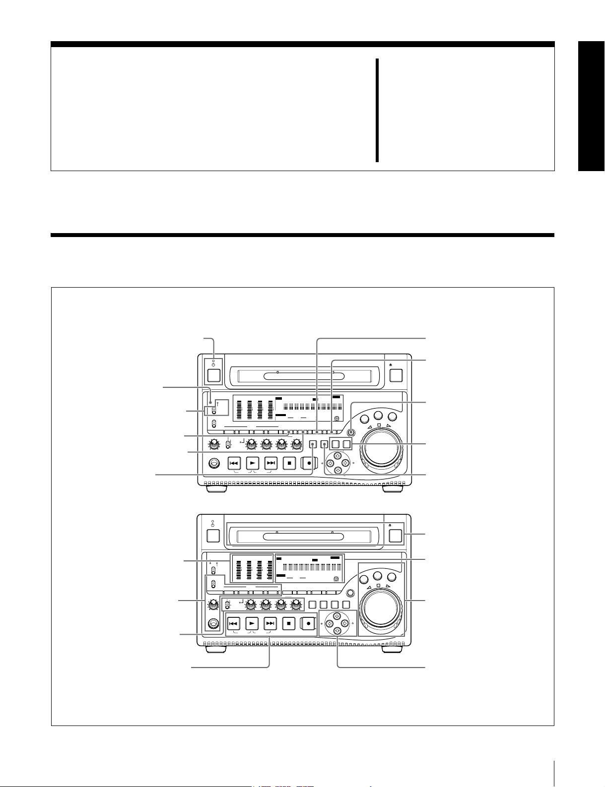
2-1 Front Panel
1 On/standby switch and indicator
2 ACCESS indicator
3 Remote control switch and
NETWORK access indicator
4 VIDEO INPUT SEL button
5 COUNTER SELECT button
6 SUBCLIP button
ACCESS
MONITOR
PHONES
SGDATA
ANA SDI
AE8/EBU
dB
OVER
0
-12
-12
NETWORK
-20
-20
LOCAL
REMOTE
-30
-30
-40
-40
-60
-60
CH
- 15
L
MIX
R
MONITOR SEL
METER SEL INPUT CH INPUT SEL
ALL/CH-1 CH-2 CH-3 CH-4
VARIABLE
REC
PRESET
PB
PREV
TOP
F REV F FWD
Parts
Chapter
2
7 HOLD button
EJECT
SGDATA
SGDATA
SGDATA
ANA SDI
ANA SDI
ANA SDI
AE8/EBU
dB
0
CH
INPUT
AE8/EBU
AE8/EBU
i.LINK
dB
dB
OVER
OVER
OVER
0
0
SDI
CMPST
-12
-12
Y-R,B
-20
-20
SG
-30
-30
-40
-40
MONITOR
-60
-60
1/2
- 26
AUDIO
PLAY
3/4
CH
- 37
CH
- 48
5/6
7/8
VIDEO
INPUT SEL
NEXT
END
]
EDIT KEY INHREMOTE [9P iLINK
VITC VITCCOUNTER REC INHVIUB
HOURS MINUTES SECONDS FRAMES
AUDIO
18 24 BIT
4 8 CH
COUNTER
SELECT
STOP
625
IMX[50 40 30
525
DVCAM
HOLD
SUB
THUMB
CLIP
NAIL
ESSENCE
CLIP
MARK
MENU
REC
IN OUT
]
SYS MENU
MENU
ALARM
SET RESET
S.SEL
G
O
J
V
A
E
L
T
T
U
H
S
SHIFT
MARK1
MARK2
8 MENU button
9 SHIFT button
R
0 SET and RESET buttons
qa THUMBNAIL button
1 Audio level meter section
(see page 21)
2 Audio settings section
(see page 21)
3 Audio level adjustment
section (see page 22)
4 Recording and playback
control section (see page 22)
ACCESS
MONITOR
PHONES
SGDATA
SGDATA
ANA SDI
ANA SDI
AE8/EBU
AE8/EBU
dB
dB
OVER
0
-12
-12
NETWORK
-20
-20
LOCAL
REMOTE
-30
-30
-40
-40
-60
-60
CH
- 15
CH
L
MIX
R
MONITOR SEL
METER SEL INPUT CH INPUT SEL
ALL/CH-1 CH-2 CH-3 CH-4
VARIABLE
REC
PRESET
PB
PREV
TOP
F REV F FWD
EJECT
qs Disc slot and EJECT button
SGDATA
SGDATA
ANA SDI
ANA SDI
INPUT
AE8/EBU
AE8/EBU
i.LINK
dB
dB
OVER
OVER
OVER
0
0
0
SDI
CMPST
-12
-12
Y-R,B
-20
-20
SG
-30
-30
-40
-40
MONITOR
-60
-60
1/2
- 26
AUDIO
PLAY
3/4
CH
- 37
CH
- 48
5/6
7/8
INPUT SEL
NEXT
END
]
EDIT KEY INHREMOTE [9P iLINK
VITC VITCCOUNTER REC INHVIUB
HOURS MINUTES SECONDS FRAMES
AUDIO
18 24 BIT
4 8 CH
VIDEO
COUNTER
SELECT
STOP
625
IMX[50 40 30
525
DVCAM
HOLD
SUB
THUMB
CLIP
ESSENCE
CLIP
MENU
REC
IN OUT
]
SYS MENU
MENU
NAIL
MARK
ALARM
SET RESET
S.SEL
MARK1
MARK2
SHIFT
G
O
J
V
A
E
L
T
T
U
H
S
5 Status display section
R
(see page 23)
6 Shuttle/jog/variable
control block (see page 25)
7 Arrow buttons (see
page 25)
2-1 Front Panel
19

a On/standby (1) switch and indicator
When the POWER switch on the rear panel is in the ^
position, this switches the PDW-1500 between the
operating state (the indicator is lit green) and the standby
• Test video signal from the internal signal generator
The INPUT display in the status display section changes,
to reflect the selection, as follows:
i.LINKtSDItCMPSTtSG
state (the indicator is lit red).
When the indicator is lit red, pressing the switch makes the
indicator flash green. When the PDW-1500 is in the
Chapter 2 Names and Functions of Parts
operating state, the indicator lights continuously green.
When the indicator is lit green, pressing the switch makes
the indicator flash. When the PDW-1500 is in the standby
state, the indicator lights red.
When using the PDW-1500, normally leave the rear panel
POWER switch in the ^ (on) position, and use this switch
to switch the PDW-1500 between the operating state and
standby state.
Note
Input signals (AV/C) from the S400 (i.LINK) connector
cannot be recorded when the basic menu item 031
“RECORDING FORMAT” is set to “IMX 50,” “IMX40,”
or “IMX 30.” E-E video display and audio output are also
not possible.
Select a signal other than “i.LINK” to record IMX format
video signals. When i.LINK input signals are selected, set
basic menu item 031“RECORDING FORMAT” to
“DVCAM.”
b ACCESS indicator
This lights when the disc is accessed and when a file is
opened by a FAM or FTP connections (see page 74). If the
on/standby switch is pressed while this indicator is lit,
access to the disc is completed before the unit switches to
the standby state.
Note
While the ACCESS indicator is lit, do not turn off the
POWER switch on the rear panel or disconnect the power
cord. This could lead to a loss of data from the disc.
c Remote control switch and NETWORK access
indicator
Different positions of the switch allow different operations
as follows.
NETWORK: Enables access to the network. The
indicator lights when an external network device is
being accessed. In this state, operation from the front
panel is not possible.
LOCAL: Enables operation from the front panel.
REMOTE: Enables remote control of the PDW-1500
from a device connected to the S400 (i.LINK)
connector or REMOTE connector on the rear panel.
Use extended menu item 214 “REMOTE
INTERFACE” to select which of the connectors is
used.
See 8-3-2 “Extended Menu Operations” (page 102)
for more information about how to make extended
menu settings.
d VIDEO INPUT SEL (selection) button
Pressing this button cycles the video input signal through
the following selections.
• i.LINK-compliant DVCAM format digital signal
(i.LINK input comprising both video and audio signals)
input to the S400 (i.LINK) connector
• SDI video signal input to the SDI IN connector
• Composite video signal input to the VIDEO IN
connector
See 8-2-2 “Basic Menu Operations” (page 88) for more
information about how to make basic menu settings.
e COUNTER SELECT button
This cycles the data displayed in the time data display
through the sequence TC, UB, and COUNTER.
TC: The playback time code read by the internal time code
reader, or the time code generated by the internal time
code generator
Make the TC or VITC selection in extended menu item
629 “TC SELECT.”
UB: The user bits inserted in the playback time code, or
user bits generated by the internal time code generator
COUNTER: The elapsed recording/playback time (hours,
minutes, seconds, frames). This can be reset by
pressing the RESET button (see page 21).
The corresponding indicator above the time data display
lights according to the setting.
f SUBCLIP button
To play back following a clip list, press this button, turning
it on. This is also effective for jog and shuttle operations.
To play clips in the order they are recorded, press this
button again, turning it off.
Note
If no clip list is registered, this button does not light when
pressed. The operation is invalid.
g HOLD button
Press this button to stop the time code generator.
Also, when setting the time code or user bits to be
recorded, press this button first, to hold the values.
h MENU button
Use for setup menu and system menu operations. Pressing
this button displays the setting of a menu item in the status
display section.
The same information is also superimposed on the display
on a monitor connected to the PDW-1500.
Press once more to return to the original display.
20
2-1 Front Panel
i SHIFT button
E
T
T
40
40
40
40
4
MONITOR
Use to switch the functions of various buttons.
j SET and RESET buttons
Use these as follows.
SET button: Use for setup menu settings, scene selection
settings, and so on.
RESET button: Press to reset the counter. This is also
used to cancel setup menu settings and abandon scene
selection (thumbnail search).
k THUMBNAIL button
To carry out a thumbnail search or create a clip list, press
this button turning it on. Thumbnail images representing
each clip or sub-clip appear. Press once more to turn the
button off, and return to a whole-screen display.
To display the thumbnails of essence mark frames (frames
with an essence mark attached), hold down the SHIFT
button, and press this button. The essence mark selection
menu appears. Select the desired type of essence mark, and
the corresponding essence mark frames appear in
thumbnails. Press once more, turning the button off, to
return to a whole-screen display.
l Disc slot and EJECT button
Insert a disc in the disc slot. To remove the disc, press the
EJECT button.
b Audio input display
For each channel, the following indicators light to show
the type of the selected audio input signal.
ANA: Analog audio signal
SDI: SDI audio signal
AES/EBU: AES/EBU format digital audio signal
SG: Audio test signal generated by the internal signal
generator
DATA: Non-audio signal
Make the audio input signal selection with the AUDIO
INPUT SEL button (see page 22).
2 Audio settings section
1 MONITOR switch
2 AUDIO MONITOR SEL button
3 AUDIO METER SEL button
4 AUDIO INPUT CH button
5 AUDIO INPUT SEL button
-60
-60
-60
-60
1/2
MONITOR
PHONES
L
MIX
R
MONITOR SEL
VARIABLE
PREV
CH
-
15
CH
-
26
AUDIO
METER SEL INPUT CH INPUT SEL
ALL/CH-1 CH-2 CH-3
REC
PRESET
PB
PLAY
3/4
CH
-
37
CH
-
48
5/6
7/8
VID
INPU
NEXT
S
Chapter 2 Names and Functions of Parts
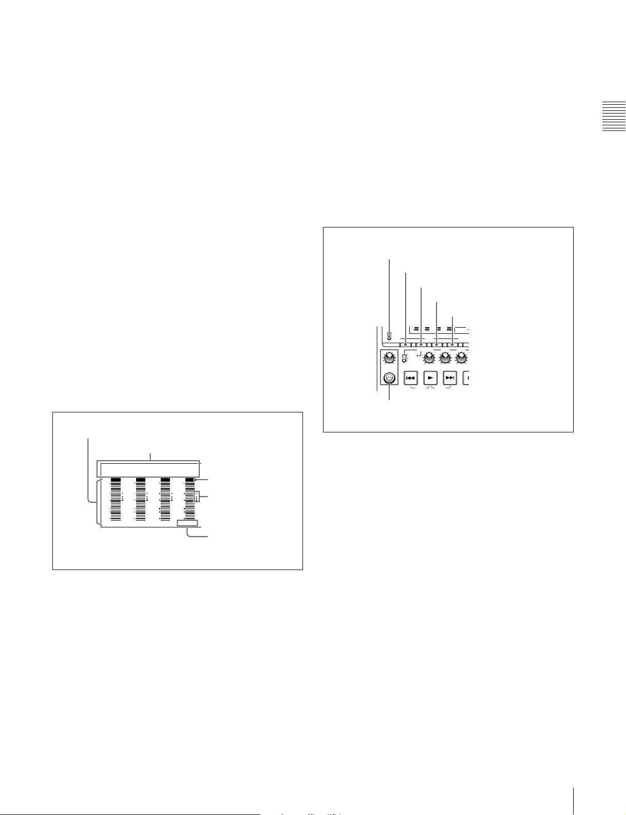
1 Audio level meter section
1 Audio level meters
SG DATA
ANA SDI
AE8/EBU
dB
OVER
0
-12
-20
-30
-40
-60
CH
- 15
a Audio level meters
Depending on the setting of the AUDIO METER SEL
button (see page 22), these show the audio recording levels
(during recording) or audio playback levels (during
playback) of channels 1 to 4 or channels 5 to 8. If an audio
level exceeds 0 dB, the OVER indicator lights.
By means of a maintenance menu setting, you can display
a reference level indicator (“-”) to the right of each meter
when recording.
For details of the maintenace menu, see 8-4 “Maintenance
Menu” on page 106.
2 Audio input display
SG DATA
SG DATA
ANA SDI
AE8/EBU
dB
OVER
0
-12
-20
-30
-40
-60
CH
- 37
SG DATA
ANA SDI
AE8/EBU
dB
0
-12
-20
-30
-40
-60
CH
ANA SDI
AE8/EBU
dB
0
-12
-20
-30
-40
-60
CH
- 26
OVER
OVER
- 48
OVER indicator
Reference level
indicator
Channel display
TOP
F REV F FWD
END
6 PHONES jack and volume control knob
a MONITOR switch
Of the two channels (left and right) selected by the AUDIO
MONITOR SEL button (see next item), selects whether
both or one is monitored.
L: The left channel audio is output from the PHONES jack
and the AUDIO MONITOR OUT connector.
R: The right channel audio is output from the PHONES
jack and the AUDIO MONITOR OUT connector.
MIX: Stereo audio is output from the PHONES jack.
Monaural audio, the left and right channels mixed, is
output from the AUDIO MONITOR OUT connector.
b AUDIO MONITOR SEL (selection) button
Of the up to eight audio signal channels, the audio of the
two channels (left and right channels in the case of a stereo
output) selected by this button can be monitored with the
PHONES jack on the front panel and the AUDIO
MONITOR OUT connector on the rear panel.
Pressing this button cycles through the four of the
following channel combinations.
• Channels 1 (left) and 2 (right)
• Channels 3 (left) and 4 (right)
• Channels 5 (left) and 6 (right)
• Channels 7 (left) and 8 (right)
2-1 Front Panel
21
In the status display section, the MONITOR display (see
page 23) changes to reflect the selection.
The factory default is for channels 1 (left) and 2 (right) to
be selected.
You can select whether to monitor both of the selected
channels or only one, using the MONITOR switch (see
page 21).
Chapter 2 Names and Functions of Parts
c AUDIO METER SEL (selection) button
monitored channel is selected by the AUDIO MONITOR
SEL button (see page 21) and MONITOR switch (see page
21).
Non-audio signals are muted.
Adjust the volume with the knob. You can also cause this
to simultaneously adjust the output volume from the
AUDIO MONITOR OUT connector on the rear panel. To
do this, in the setup menu, set extended menu item 114
“AUDIO MONITOR OUTPUT LEVEL” to “var.”
When using MPEG IMX format in eight-channel mode,
select whether the audio level meters should display
channels 1 to 4 or channels 5 to 8.
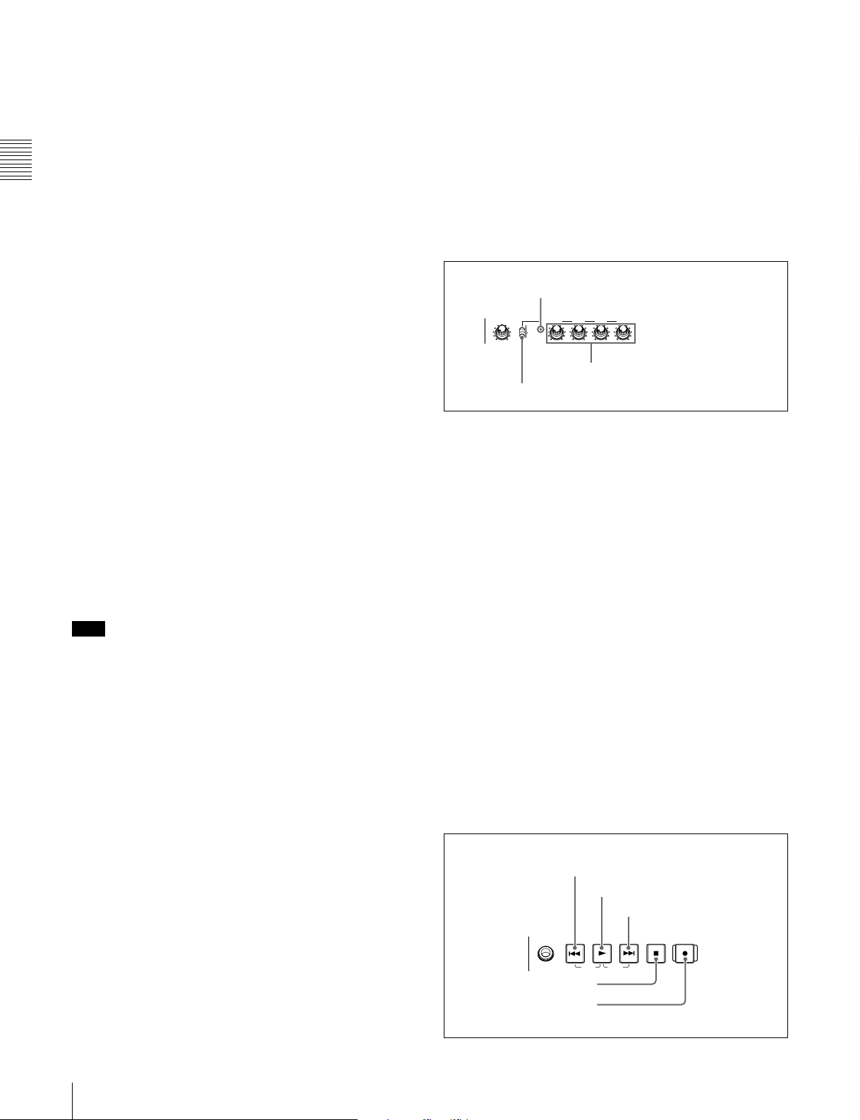
3 Audio level adjustment section
Pressing this button toggles the selection, and the audio
level meter channel display also changes.
ALL indicator
The factory default is for channels 1 to 4 to be selected.
ALL/CH-1 CH-2 CH-3 CH-4
VARIABLE
REC
PRESET
d AUDIO INPUT CH (channel) button
PB
This selects the channel to which the audio input signal
selection applies.
Pressing this button cycles through the following states of
2 ALL/CH-1, CH-2 to CH-4 adjustment knobs
1 VARIABLE switch
the audio level meter channel display.
• Channel 1 flashing
• Channel 2 flashing
• Channel 3 flashing
• Channel 4 flashing
• Channels 1 to 4 lit
When a channel is flashing, you can select the audio input
signal using the AUDIO INPUT SEL button.
a VARIABLE (audio level adjustment selector)
switch
This selects which of the input audio and playback audio
has the level adjusted by the ALL/CH-1, and CH-2 to CH4 adjustment knobs.
REC: Adjust the input audio levels. The playback audio
levels are fixed at their preset values.
When audio is in eight-channel mode
On channels 5 to 8, you can input only the audio signals
embedded in an SDI signal.
PRESET: Do not adjust the audio levels.
PB: Adjust the playback audio levels. The input audio
levels are fixed at their preset values.
Note
After completing the selection of the audio input signals
with the AUDIO INPUT SEL button, return the audio level
meters to the state in which all channel indications are lit.
e AUDIO INPUT SEL (selection) button
This selects the input signal to the channel with a flashing
display, that has been selected with the AUDIO INPUT
CH button described above.
Pressing this button cycles the selection of the audio input
signal, and the audio input display above the audio level
meter changes to reflect this.
ANA: Analog audio signal input to the AUDIO IN
connector
SDI: SDI audio signal input to the SDI IN connector
AES/EBU: AES/EBU format digital audio signal input to
the DIGITAL AUDIO (AES/EBU) IN connector
SG: Audio test signal generated by the internal signal
generator
f PHONES jack and volume control knob
The jack is a standard stereo jack. Connect stereo
headphones with an impedance of 8 ohms, to monitor the
audio during recording, playback, and editing. The
b ALL/CH-1, CH-2 to CH-4 (audio level) adjustment
knobs
Depending on the setting of the VARIABLE switch, these
adjust the input audio or playback audio levels of channels
1 to 4.
By the setting of extended menu item 131 “AUDIO
VOLUME,” you can enable the ALL/CH-1 knob to
simultaneously adjust all eight channels. When this
simultaneous adjustment is enabled the ALL indicator
lights.
4 Recording and playback control section
1 PREV button
2 PLAY button
3 NEXT button
PHONES
PREV
TOP
4 STOP button
5 REC button
PLAY
F REV F FWD
NEXT
REC
STOP
END
22
2-1 Front Panel
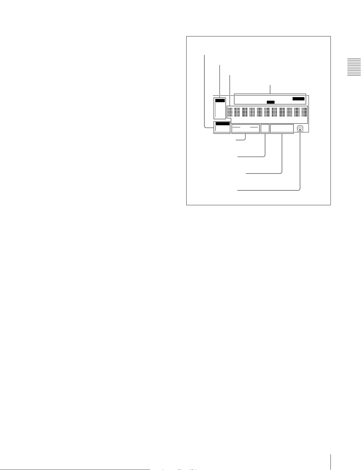
a PREV (previous) button
Press this button, turning it on, to show the first frame of
the current clip. While the first frame of a clip is shown,
pressing this button jumps to the beginning of the previous
clip.
This button is also used together with other buttons for the
following operations.
Reverse direction high-speed search: Hold down the
PLAY button, and press this button. A high-speed
search in the reverse direction is carried out.
Displaying the first frame of the first clip: Hold down
the SHIFT button, and press this button.
b PLAY (playback) button
To start playback, press this button, turning it on.
5 Status display section
1 MONITOR display
2 INPUT display
3 Time data display
4 Indicators above the time data display
INPUT
i.LINK
SDI
CMPST
Y-R,B
SG
MONITOR
1/2
5/6
EDIT KEY INHREMOTE [9P iLINK
VITC VITCCOUNTER REC INHVIUB
HOURS MINUTES SECONDS FRAMES
3/4
AUDIO
7/8
4 8 CH
18 24 BIT
625
525
]
IMX[50 40 30
DVCAM
Chapter 2 Names and Functions of Parts
ALARM
]
c NEXT button
Press this button, turning it on, to jump to the next clip, and
show the first frame.
This button is also used together with other buttons for the
following operations.
Forward direction high-speed search: Hold down the
PLAY button, and press this button. A high-speed
search in the forward direction is carried out.
Displaying the last frame of the last clip: Hold down the
SHIFT button, and press this button.
d STOP button
To stop recording or playback, press this button, turning it
on. The frame at the stop point appears.
The unit enters standby off mode when you press this
button with the SHIFT button held down. It returns from
standby off mode to the original state when you press this
button again with the SHIFT button held down. (The lit or
unlit status of the STOP button does not change.)
This unit can automatically enter standby mode whenever
a specified time elapses in disc stop mode. For details, see
the description of extended menu item 501 “STILL
TIMER” (page 96).
e REC (record) button
To start recording, hold down this button, and press the
PLAY button. The recording takes place on an unrecorded
part of the disc.
To stop recording, press the STOP button.
This creates a clip of the recorded portion.
5 AUDIO indicators
6 525/625 indicator
7 IMX/DVCAM indicator
8 Disc loaded mark
a MONITOR (audio monitor channel selection)
display
This shows the audio channels selected by the AUDIO
MONITOR SEL button (see page 21). The displayed
channel audio is output from the PHONES jack on the
front panel and the AUDIO MONITOR OUT connector on
the rear panel, according to the setting of the MONITOR
switch (see page 21).
1/2: channels 1 (left) and 2 (right)
3/4: channels 3 (left) and 4 (right)
5/6: channels 5 (left) and 6 (right)
7/8: channels 7 (left) and 8 (right)
b INPUT (video input signal) display
Shows the currently selected video input signal.
i.LINK: i.LINK compliant DVCAM format digital signal
SDI: SDI video signal
CMPST: Composite video signal
SG: Test video signal from the internal signal generator
Make the video signal input selection with the VIDEO
INPUT SEL button (see page 20).
c Time data display
Normally, this shows the disc playback time, time code, or
user bit information, as selected by the COUNTER
SELECT button (see page 20) and extended menu item
629 “TC SELECT.”
It is also used for error messages, setup menus, and other
displays.
2-1 Front Panel
23

d Indicators above the time data display
There are the following indicators.
For details, see 9-2 “Error Messages” (page 114) and 93 “Alarms” (page 115).
EDIT indicator: This lights when an “Audio Edit Preset”
command is received from an external editor.
REMOTE (9P/i.LINK) indicator: This shows “9P” or
“i.LINK” as follows.
• 9P: When extended menu item 214 “REMOTE
Chapter 2 Names and Functions of Parts
INTERFACE” is set to “9PIN.”
• i.LINK: When extended menu item 214 “REMOTE
INTERFACE” is set to “i.LINK.”
COUNTER indicator: This lights when a counter value
(hours, minutes, seconds, and frames, resettable) is
displayed in the time data display.
TC/VITC (time code type) indicator: This lights when
the COUNTER SELECT button (see page 20) is set to
TC. The time data display shows the time code.
When extended menu item 629 “TC SELECT” is set
to “TC,” this shows “TC,” and when “VITC” is
selected, it shows “VITC.”
UB/VIUB (user bit type) indicator: This lights when the
1) E-E mode: Abbreviation of Electric to Electric mode. The mode in which
input video and audio signals are output after passing only through the
electrical circuits.
e AUDIO indicators
During playback, these show the number of channels
recorded on the disc and the number of quantizing bits.
During E-E mode display, the number of recorded
channels and number of data bits set by the maintenance
menu item “AUDIO CONFIG” are shown.
Number of recorded channels:
• 4ch: 4 channels
• 8ch: 8 channels
Number of quantizing bits:
• 16bit: 16 bits
• 24bit: 24 bits
When the DVCAM format is used, these are always 4
channels and 16 bits.
COUNTER SELECT button is set to UB. The time
data display shows the user bits.
When extended menu item 629 “TC SELECT” is set
For details of the maintenace menu, see 8-4 “Maintenance
Menu” on page 106.
to “TC,” this shows “UB,” and when “VITC” is
selected it shows “VIUB.”
indicator: This lights in the following cases.
VITC
• In playback mode, when VITC is being read.
(Regardless of what the time data display is
showing.)
• When VITC is being recorded, or in E-E mode
when VITC is recorded due to one of the following
1)
f 525/625 (TV system) indicator
This shows the TV system selected in basic menu item 013
“525/625 SYSTEM SELECT.”
525 (U): NTSC, 525 scan lines, field frequency 59.94 Hz
525 (J): NTSC (for Japan), 525 scan lines, field frequency
59.94 Hz
625: PAL, 625 scan lines, field frequency 50 Hz
conditions.
- Extended menu item 619 “VITC” is set to “on.”
- There is VITC in the selected video input signal,
and that line has been set to “thru” with extended
menu item 723 “INPUT VIDEO BLANK.”
REC INH (recording inhibited) indicator: This lights in
the following cases.
• When a disc with recording inhibited is loaded.
• When extended menu item 310 “REC INHIBIT” is
set to “on.”
• The format of the recorded part of the disc does not
match the settings of the PDW-1500 (number of
g IMX/DVCAM (recording/playback format)
indicator
During playback, this shows the recording format of the
inserted disc. During E-E display, including recording
mode, and during FAM and FTP connections (see page
74), this shows the recording format set by basic menu
item 031 “RECORDING FORMAT.”
IMX50: MPEG IMX 50 format
IMX40: MPEG IMX 40 format
IMX30: MPEG IMX 30 format
DVCAM: DVCAM format
recorded channels, TV system (525/625 selection),
and recording format (DVCAM/IMX50/IMX40/
IMX30 selection)).
KEY INH (key inhibit) indicator: This lights when
h Disc loaded mark
This lights while a disc is loaded in the PDW-1500. It
flashes as the disc is inserted, and while it is being ejected.
“MON./INPUT SEL” or “CONTROL PANEL” is set
to “on” with extended menu item 118 “CONTROL
PANEL.”
ALARM
indicator: This lights when condensation
within the PDW-1500, a laser diode fault, or another
hardware error is detected. It goes off when the error
state is cleared. When this indicator is lit, the time data
display shows an error message.
24
2-1 Front Panel
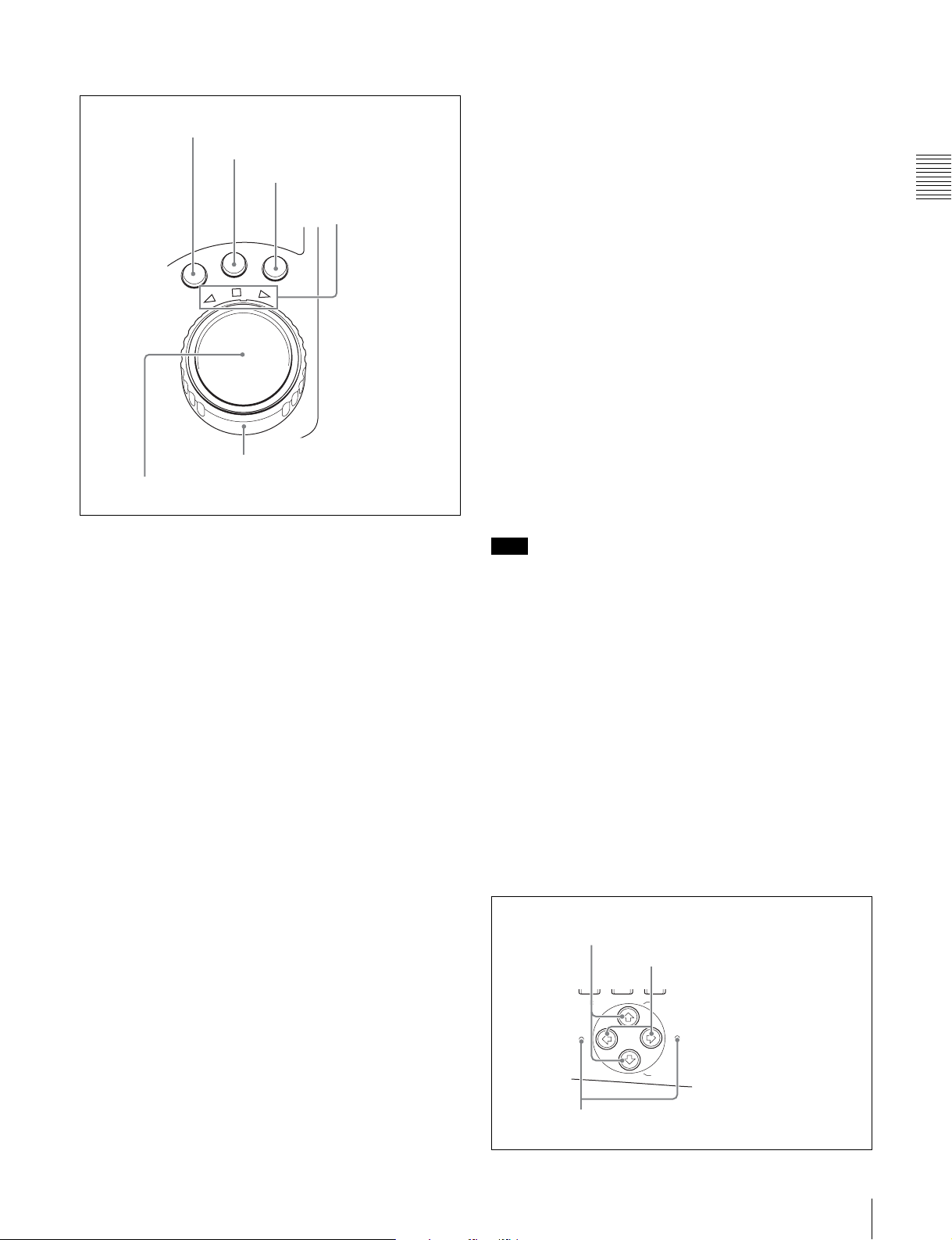
6 Shuttle/jog/variable control block
S
H
U
T
T
L
E
J
O
G
V
A
R
1 SHUTTLE button
2 JOG button
3 VAR button
4 Jog/shuttle transport
indicators
6 Shuttle dial
5 Jog dial
mode directly by turning the dial (set extended menu item
101 “SELECTION FOR SEARCH DIAL ENABLE” to
“dial”).
f Shuttle dial
Turn this for playback in shuttle mode or variable speed
mode. Turn clockwise for forward direction playback, and
counterclockwise for reverse direction playback.
• In shuttle mode, the playback speed varies in the range
±35 times normal speed (using MPEG IMX/DVCAM),
according to the angular position of the shuttle dial.
• In variable speed mode, you can finely adjust the
playback speed from –2 to +2 times normal speed,
according to the angular position of the shuttle dial. You
can vary this playback speed range in extended menu
item 301 “VAR SPEED RANGE FOR
SYNCHRONIZATION.”
The shuttle dial has a detent at the center position, for still
image playback.
Normally, you press the SHUTTLE button before turning
the shuttle dial, but it is also possible to make a setting to
enable shuttle mode directly by turning the dial (set
extended menu item 101 “SELECTION FOR SEARCH
DIAL ENABLE” to “dial”).
Chapter 2 Names and Functions of Parts
For details of playback operations with these buttons and
dials, see 4-2-2 “Playback Operation” on page 56.
Note
When extended menu item 101 “SELECTION FOR
SEARCH DIAL ENABLE” is set to “dial,” after using the
a SHUTTLE button
To play back in shuttle mode using the shuttle dial, press
this button, turning it on. Pressing the JOG button or
turning the jog dial switches to jog mode.
shuttle dial, return it to the center position. If the shuttle
dial is not in the center position, it is possible occasionally
for vibration from other operations to activate the dial, and
start playback in shuttle mode.
b JOG button
To play back in jog mode using the jog dial, press this
button, turning it on. Pressing the SHUTTLE button or
turning the shuttle dial switches to shuttle mode.
7 Arrow buttons
The four arrow buttons are also used as the MARK1
button, MARK2 button, IN button, and OUT button. The
correspondence with the buttons is as follows.
c VAR (variable) button
To play back in variable speed mode using the shuttle dial,
press this button, turning it on.
F button: MARK1 button
f button: MARK2 button
G button: IN button
g button: OUT button
d Jog/shuttle transport indicators
These show the playback direction in jog, shuttle, or
You can use these buttons for thumbnail selection, menu
setting operations, setting IN/OUT points, and so on.
variable speed mode.
b (green): Lights during playback in the reverse direction.
B (green): Lights during playback in the forward direction.
x (red): Lights during still image display.
e Jog dial
Turn this for playback in jog mode. Turn clockwise for
forward direction playback, and counterclockwise for
reverse direction playback. In jog mode, the playback
speed varies in the range ±1 times normal speed, according
to the rotation rate of the jog dial. There are no detents.
Normally, you press the JOG button before turning the jog
dial, but it is also possible to make a setting to enable jog
1 F/MARK1 button and f/MARK2 button
2 G/IN button and g/OUT button
ESSENCE
S.SEL
MARK
IN OUT
3 IN indicator and OUT indicator
MARK1
MARK2
2-1 Front Panel
25

a F/MARK1 button and f/MARK2 button
When the THUMBNAIL button (see page 21) is lit, you
can use these for thumbnail selection.
During recording and playback, the F/MARK1 and f/
MARK2 buttons can be pressed with the SET button held
down to record a shot mark 1 or shot mark 2 as an essence
mark.
Chapter 2 Names and Functions of Parts
To delete or change essence marks, use the supplied PDZ1 Proxy Browsing Software.
b G/IN button and g/OUT button
When the THUMBNAIL button (see page 21) is lit, you
can use these for thumbnail selection.
An In or Out point is set when you press the SET button
with the G/IN or g/OUT button held down. The In or Out
point setting is deleted when you press the RESET button
with the G/IN or g/OUT button held down.
c IN indicator and OUT indicator
IN indicator: When an IN point is set, this lights.
If an attempt is made to set the IN point after a
recorded OUT point, this flashes.
OUT indicator: When an OUT point is set, this lights.
If an attempt is made to set the OUT point before a
recorded IN point, this flashes.
26
2-1 Front Panel
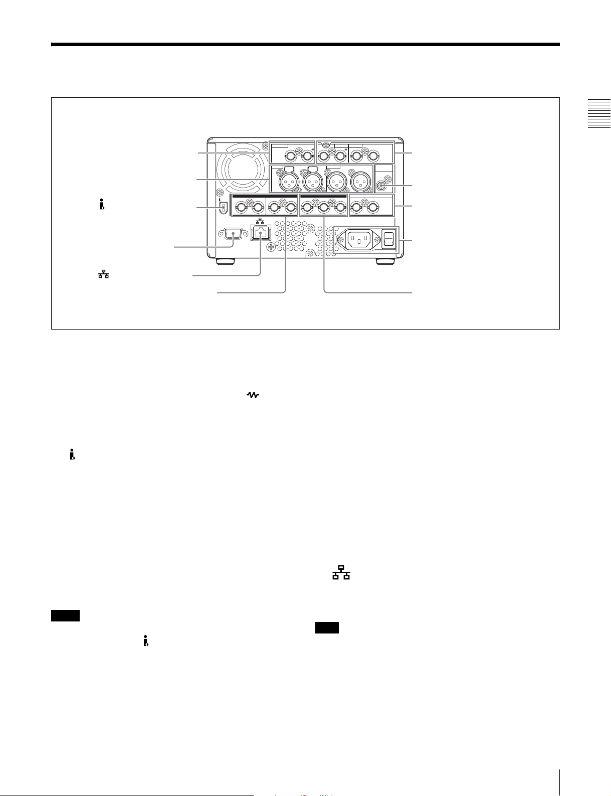
2-2 Rear Panel
1 REF. VIDEO IN connectors
AUDIO IN
1 Analog audio signal inputs/
outputs (see page 28)
2 S400 (i.LINK) connector
3 REMOTE connector
4 (network) connector
2 Digital audio signal inputs/outputs
(see page 28)
DIGITAL AUDIO (AES/EBU)
1/2IN 3/4 IN
S400
REMOTE
1/2OUT 3/4 IN OUT
a REF. VIDEO IN (reference video signal input)
connectors (BNC type)
The two connectors form a loop-through connection; when
a reference video signal is input to the left connector, the
same signal is input from the right connector ( ) to a
connected device. When no connection is made to the right
connector, the left connector is automatically terminated
with an impedance of 75 ohms.
b S400 (i.LINK) connector (6-pin, IEEE1394
compliant)
Connect a DV device, computer, or similar, using an
i.LINK cable.
When the unit is shipped from the factory, the audio output
signal is set to 16 bit/48 kHz/2ch mode. You can change
the audio mode and output channel settings with extended
menu item 831 “DV OUT AUDIO MODE” and extended
menu item 828 “SDI AUDIO OUTPUT SELECT.”
VIDEO INREF.VIDEO IN VIDEO OUT
1/3 2/4
12
AUDIO OUT
1/3 2/4
SDI TIME CODE
OUT 1 2 (SUPER)
(SUPER)
AUDIO
MONITOR OUT
3Analog video signal inputs/
outputs (see page 28)
5 AUDIO MONITOR OUT connector
4Time code inputs/outputs
(see page 29)
5 Power supply section
(see page 29)
6 SDI signal inputs/
outputs (see page 29)
still connected, a current from an excessive voltage (8 to
40 V) output from the i.LINK connector of the device
flows into the PDW-1500. This may cause a failure of
the PDW-1500.
• When connecting the PDW-1500 to a device with a 6-pin
i.LINK connector, connect to the 6-pin i.LINK
connector of the other device first.
• Except in playback mode (jog and shuttle modes, etc.), if
you are monitoring the audio signal output from this
connector on another device, the audio signal may sound
differently from the audio signal played back on the
PDW-1500.
c REMOTE (remote control signal) connector (D-
sub 9-pin)
To control the PDW-1500 from a controller or VTR
supporting the RS-422A Sony 9-pin VTR protocol,
connect the device to this connector.
Chapter 2 Names and Functions of Parts
See 8-3-2 “Extended Menu Operations” (page 102) for
more information about how to make these settings.
Notes
• If video or audio signals from an external device
connected with the S400 (i.LINK) connector are not
output, disconnect the i.LINK cable and connect it again,
pushing it straight in.
• When the PDW-1500 is connected to a device with a 6pin i.LINK connector by an i.LINK cable, before
unplugging the i.LINK cable, first power off the device
and disconnect the power plug from the outlet. If the
i.LINK cable is unplugged with the device power plug
d (network) connector (RJ-45 type)
This is a 10Base-T/100Base-TX/1000Base-T connector
for network (Ethernet) connection.
Note
For safety, when connecting external devices to this
connector, do not connect connectors which may have
excessive voltage. Follow the instructions in this manual
when making connections.
e AUDIO MONITOR OUT connector (RCA-pin)
This outputs an audio signal for monitoring.
2-2 Rear Panel
27
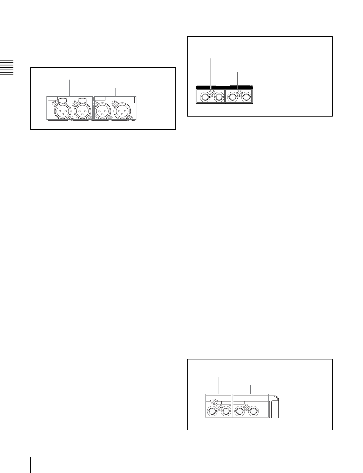
The monitored channel is selected by the combination of
the AUDIO MONITOR SEL button (see page 21) and
MONITOR switch (see page 21).
2 Digital audio signal inputs/outputs
1 Analog audio signal inputs/outputs
Chapter 2 Names and Functions of Parts
1 AUDIO IN 1/3, 2/4 connectors
2 AUDIO OUT 1/3, 2/4 connectors
AUDIO IN AUDIO OUT
1/3 2/4 1/3 2/4
1 DIGITAL AUDIO (AES/EBU) IN 1/2, 3/4 connectors
2 DIGITAL AUDIO (AES/EBU)
OUT 1/2, 3/4 connectors
DIGITAL AUDIO (AES/EBU)
1/2IN 3/4 1/2OUT 3/4
a DIGITAL AUDIO (AES/EBU) IN (digital audio
input) 1/2, 3/4 connectors (BNC type)
a AUDIO IN (analog audio signal input) 1/3, 2/4
connectors (XLR 3-pin, female)
These are analog audio signal input connectors.
With the AUDIO INPUT SEL button (see page 22), you
can select whether the signal input to connector 1/3 is
These input AES/EBU format digital audio signals. When
the unit is shipped from the factory, the 1/2 connector is set
to audio channel 1/2, and the 3/4 connector is set to audio
channel 3/4. You can change these settings with extended
menu item 827 “AES/EBU AUDIO OUTPUT SELECT.”
assigned to audio channel 1or 3, and whether the signal
input to connector 2/4 is assigned to audio channel 2 or 4.
You can set the reference input level with the maintenance
See 8-3-2 “Extended Menu Operations” (page 102) for
more information about how to make these settings.
menu item “AUDIO CONFIG.” (Factory default setting:
+4 dB)
b DIGITAL AUDIO (AES/EBU) OUT (digital audio
output) 1/2, 3/4 connectors (BNC type)
For details of the maintenace menu, see 8-4 “Maintenance
Menu” on page 106.
These output AES/EBU format digital audio signals. The
left connector (1/2) corresponds to audio channels 1 and 2,
and the right connector (3/4) corresponds to audio
b AUDIO OUT (analog audio signal output) 1/3, 2/4
channels 3 and 4.
connectors (XLR 3-pin, male)
These are analog audio signal output connectors.
When the unit is shipped from the factory, the 1/3
connector is set to audio channel 1, and the 2/4 connector
is set to audio channel 2. You can change these settings
with extended menu item 824 “ANALOG LINE OUTPUT
To treat the input and output signals of these connectors as
non-audio signals, set the maintenance menu item
“AUDIO CONFIG”-“NON-AUDIO INPUT” (recording)
and extended menu item 823 “NON-AUDIO FLAG PB”
(playback).
SELECT.”
You can set the output level with the maintenance menu
item “AUDIO CONFIG.” (Factory default setting: +4 dB)
Non-audio signals are muted.
See 8-3-2 “Extended Menu Operations” (page 102) for
more information about how to make extended menu
settings.
See 8-4-2 “Maintenance Menu Operations” (page 108)
See 8-3-2 “Extended Menu Operations” (page 102) for
more information about how to make these settings.
for more information about how to make maintenance
menu settings.
For details of the maintenace menu, see 8-4 “Maintenance
Menu” on page 106.
28
2-2 Rear Panel
3Analog video signal inputs/outputs
1 VIDEO IN connectors
2 VIDEO OUT 1, 2 (SUPER) connectors
VIDEO IN VIDEO OUT
12
(SUPER)
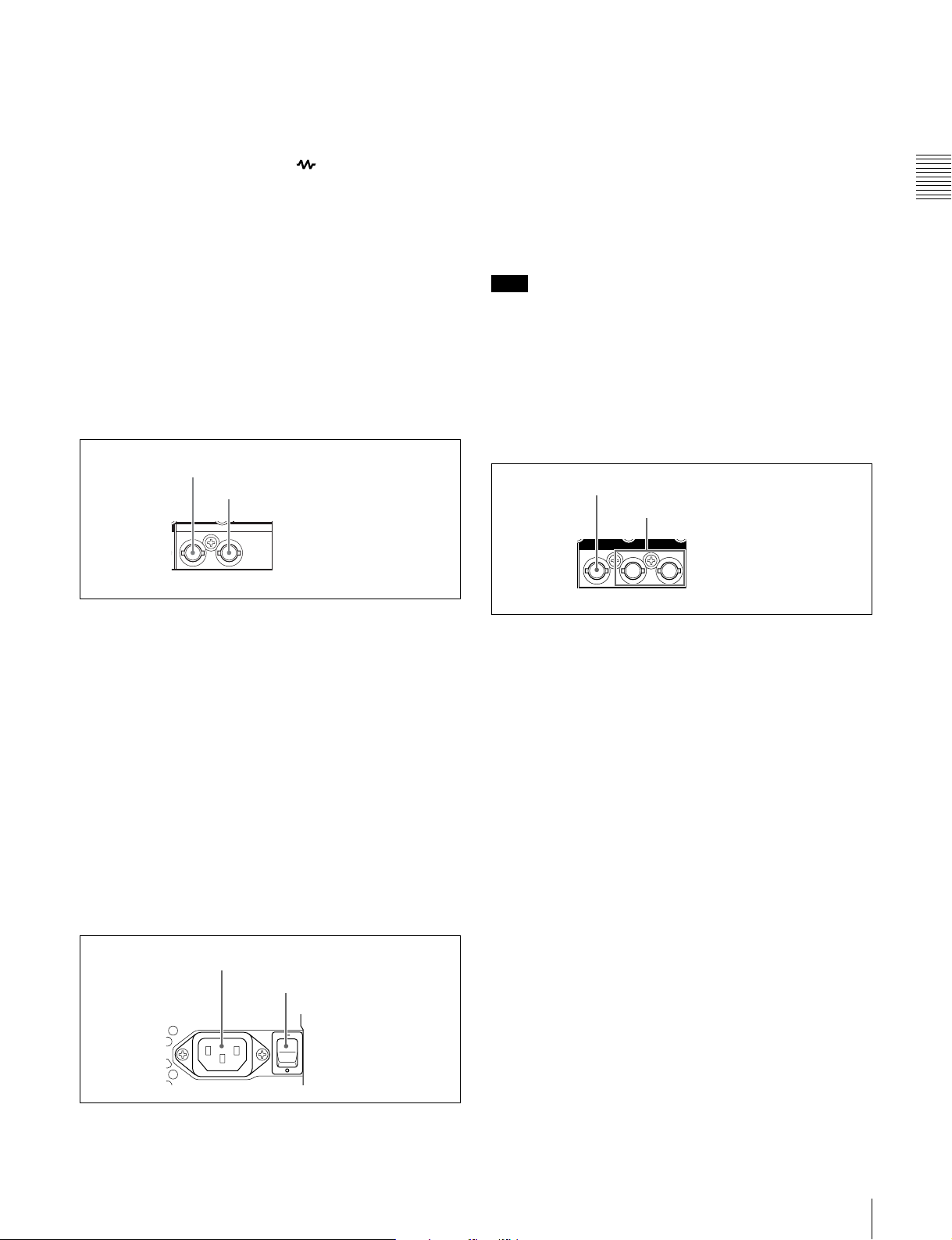
a VIDEO IN (analog video input) connectors (BNC
type)
These are composite video signal input connectors.
The two connectors form a loop-through connection; when
a signal is input to the left connector, the same signal is
output from the right connector ( ) forming a bridge
connection to the connected device.
When no connection is made to the right connector, the left
connector is automatically terminated with an impedance
of 75 ohms.
a -AC IN (AC power input) connector
Connect to an AC power supply, using an optional power
cord (see page 126).
b POWER (main power) switch
Press the ^ side to power on. Press the a side to power off.
When using the PDW-1500, normally leave the POWER
switch in the ^ (on) position, and use the on/standby switch
to switch the PDW-1500 between the operating state and
standby state.
Chapter 2 Names and Functions of Parts
b VIDEO OUT (analog video output) 1, 2 (SUPER)
connectors (BNC type)
These are composite video signal output connectors.
The output from the VIDEO OUT2 (SUPER) connector
can have time code, menu settings, alarm messages, and
other text information superimposed.
4Time code inputs/outputs
1 TIME CODE IN connector
2 TIME CODE OUT connector
TIME CODE
IN OUT
a TIME CODE IN connector (BNC type)
This inputs an SMPTE time code generated by an external
device.
b TIME CODE OUT connector (BNC type)
This outputs the following time code, depending on the
operating state of the PDW-1500.
During playback: playback time code
During recording: the time code from the internal time
code generator or the time code input to the TIME
CODE IN connector.
When extended menu item 611 “TC OUTPUT
PHASE IN EE MODE” is set to “muting,” no time
code is output.
5 Power supply section
1 -AC IN connector
2 POWER switch
POWER- AC IN
Note
When you set the on/standby switch on the front panel to
the 1 position, data is saved before powering off. Before
turning off the main power switch, be sure to check that the
on/standby switch indicator on the front panel is lit red (the
PDW-1500 is in the standby state), then press this switch
on the a side.
6 SDI signal inputs/outputs
1 SDI IN connector
2 SDI OUT1/2 (SUPER) connectors
SDI
IN
OUT 1 2 (SUPER)
a SDI IN (SDI signal input) connector (BNC type)
This inputs an SDI format video/audio signal.
When you select the signal input to this connector with the
VIDEO INPUT SEL button, in the status display section,
the INPUT display SDI indicator lights.
b SDI OUT1/2 (SUPER) (SDI signal outputs 1, 2
(superimpose)) connectors (BNC type)
When the unit is shipped from the factory, audio signal
output is 8 channels with no switching, and RP188 time
code output is set to on. You can change these settings with
extended menu item 828 “SDI AUDIO OUTPUT
SELECT” and extended menu item 920 “SD-SDI H-ANC
CONTROL.”
These output SDI format video/audio signals.
The output from the SDI OUT2 (SUPER) connector can
have time code, menu settings, alarm messages, and other
text information superimposed. To turn superimposition
off, set the maintenance menu item “OTHERS”-“SDI2
SUPER” to “OFF.”
To treat the input and output signals of these connectors as
non-audio signals, set the maintenance menu item
“AUDIO CONFIG”-“NON-AUDIO INPUT” (recording)
and extended menu item 823 “NON-AUDIO FLAG PB”
(playback).
2-2 Rear Panel
29

See 8-3-2 “Extended Menu Operations” (page 102) for
more information about how to make extended menu
settings.
See 8-4-2 “Maintenance Menu Operations” (page 108)
for more information about how to make maintenance
menu settings.
Chapter 2 Names and Functions of Parts
30
2-2 Rear Panel
 Loading...