


PROFESSIONAL DISC RECORDER
PDW-R1
OPERATION MANUAL [English] 1st Edition (Revised 1)
Important Safety Instructions
•Read these instructions.
•Keep these instructions.
•Heed all warnings.
•Follow all instructions.
•Do not use this apparatus near water.
•Clean only with dry cloth.
•Do not block any ventilation openings.
Install in accordance with the manufacturer’s instructions.
•Do not install near any heat sources such as radiators, heat registers, stoves, or other apparatus (including amplifiers) that produce heat.
•Do not defeat the safety purpose of the polarized or grounding-type plug. A polarized plug has two blades with one wider than the other. A grounding-type plug has two blades and a third grounding prong. The wide blade or the third prong are provided for your safety. If the provided plug dose not fit into your outlet, consult an electrician for replacement of the obsolete outlet.
•Protect the power cord from being walked on or pinched particularly at plugs, convenience receptacles, and the point where they exit from the apparatus.
•Only use attachments/accessories specified by the manufacturer.
•Use only with the cart, stand, tripod, bracket, or table specified by the manufacturer, or sold with the apparatus. When a cart is used, use caution when moving the cart/ apparatus combination to avoid injury from tip-over.
•Unplug this apparatus during lightning storms or when unused for long periods of time.
•Refer all servicing to qualified service personnel. Servicing is required when the apparatus has been damaged in any way, such as power-supply cord or plug is damaged, liquid has been spilled or objects have fallen into the apparatus, the apparatus has been exposed to rain or moisture, does not operate normally, or has been dropped.
WARNING
To reduce the risk of fire or electric shock, do not expose this apparatus to rain or moisture.
To avoid electrical shock, do not open the cabinet. Refer servicing to qualified personnel only.
THIS APPARATUS MUST BE EARTHED.
CAUTION
The apparatus shall not be exposed to dripping or splashing and no objects filled with liquid, such as vases, shall be placed on the apparatus.
The unit is not disconnected from the AC power source (mains) as long as it is connected to the wall outlet, even if the unit itself has been turned off.
Do not install the appliance in a confined space, such as a book case or built-in cabinet.
This apparatus is provided with a main switch on the rear panel. Install this apparatus so that user can access the main switch easily.
This symbol is intended to alert the user to the presence of uninsulated “dangerous voltage” within the product’s enclosure that may be of sufficient magnitude to constitute a risk of electric shock to persons.
This symbol is intended to alert the user to the presence of important operating and maintenance (servicing) instructions in the literature accompanying the appliance.
WARNING: THIS WARNING IS APPLICABLE FOR USA ONLY.
If used in USA, use the UL LISTED power cord specified below.
DO NOT USE ANY OTHER POWER CORD.
Plug Cap |
Parallel blade with ground pin |
|
(NEMA 5-15P Configuration) |
Cord |
Type SJT, three 16 or 18 AWG wires |
Length |
Minimum 1.5 m (4 ft. 11 in.), Less than |
|
2.5 m (8 ft. 3 in.) |
Rating |
Minimum 10 A, 125 V |
Using this unit at a voltage other than 120 V may require the use of a different line cord or attachment plug, or both. To reduce the risk of fire or electric shock, refer servicing to qualified service personnel.
WARNING: THIS WARNING IS APPLICABLE FOR OTHER COUNTRIES.
1.Use the approved Power Cord (3-core mains lead)/ Appliance Connector/Plug with earthing-contacts that conforms to the safety regulations of each country if applicable.
2.Use the Power Cord (3-core mains lead)/Appliance Connector/Plug conforming to the proper ratings (Voltage, Ampere).
2
If you have questions on the use of the above Power Cord/ Appliance Connector/Plug, please consult a qualified service personnel.
When installing the installation space must be secured in consideration of the ventilation and service operation.
•Do not block the ventilation slots at the left side and right side panels, and vents of the fans.
•Leave a space around the unit for ventilation.
•Leave more than 40 cm of space in the rear of the unit to secure the operation area.
When the unit is installed on the desk or the like, leave at least 4 cm of space in the left and right sides.
Leaving 40 cm or more of space above the unit is recommended for service operation.
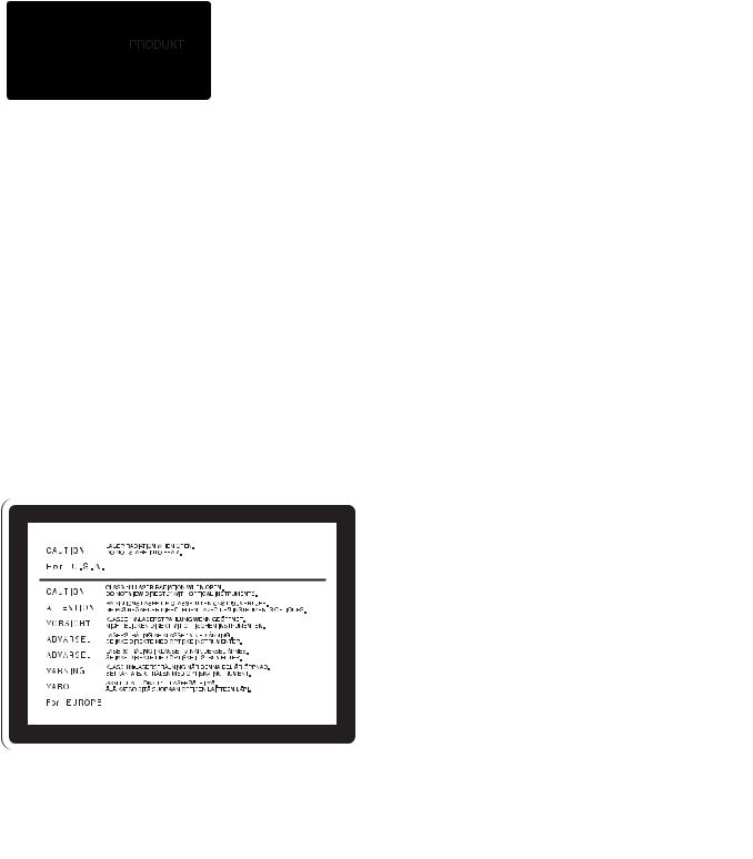
This Professional Disc Recorder is classified as a CLASS 1 LASER PRODUCT.
Laser diode properties
Wavelength: 403 to 410 nm Emission duration: Continuous
Laser output power: 65 mW (max. of pulse peak), 35 mW (max. of CW)
Tekniska data för laserdiod
Våglängd: 403 till 410 nm Emissionslängd: Kontinuerlig
Laseruteffekt: 65 mW (max. för pulstopp), 35 mW (max. för kontinuerlig våg)
Spesifikasjoner laserdiode
Bølgelengde: 403 til 410 nm Strålingens varighet: Kontinuerlig
Laserens effekt: 65 mW (maks stråletoppunkt), 35 mW (maks ved kontinuerlig stråling)
Laserdiodin ominaisuudet
Aallon pituus: 403 - 410 nm Välityksen kesto: Jatkuva
Laserlähdön teho: 65 mW (sykehuipun maks.), 35 mW (jatkuvan aallon maks.)
This label is located on the top panel of the drive unit.
Denna etikett finns på ovansidan av driftenheten.
Denne mærkat sidder på drevenhedens øverste panel.
Tämä kyltti sijaitsee ajurilaitteen yläpinnalla.
Dette merket er plassert på oversiden av driverenheten.
CAUTION
The use of optical instruments with this product will increase eye hazard.
CAUTION
Use of controls or adjustments or performance of procedures other than those specified herein may result in hazardous radiation exposure.
VAROITUS!
LAITTEEN KÄYTTÄMINEN MUULLA KUIN TÄSSÄ KÄYTTÖOHJEESSA MAINITULLA TAVALLA SAATTAA ALTISTAA KÄYTTÄJÄN TURVALLISUUSLUOKAN 1 YLITTÄVÄLLE NÄKYMÄTTÖMÄLLE LASERSÄTEILYLLE.
VARNING
OM APPARATEN ANVÄNDS PÅ ANNAT SÄTT ÄN I DENNA BRUKSANVISNING SPECIFICERATS, KAN ANVÄNDAREN UTSÄTTAS FÖR OSYNLIG LASERSTRÅLNING, SOM ÖVERSKRIDER GRÄNSEN FÖR LASERKLASS 1.
For the customers in the USA
This equipment has been tested and found to comply with the limits for a Class B digital device, pursuant to Part 15 of the FCC Rules. These limits are designed to provide reasonable protection against harmful interference in a residential installation. This equipment generates, uses, and can radiate radio frequency energy and, if not installed and used in accordance with the instructions, may cause harmful interference to radio communications. However, there is no guarantee that interference will not occur in a particular installation. If this equipment does cause harmful interference to radio or television reception, which can be determined by turning the equipment off and on, the user is encouraged to try to correct the interference by one or more of the following measures:
-Reorient or relocate the receiving antenna.
-Increase the separation between the equipment and receiver.
-Connect the equipment into an outlet on a circuit different from that to which the receiver is connected.
-Consult the dealer or an experienced radio/TV technician for help.
You are cautioned that any changes or modifications not expressly approved in this manual could void your authority to operate this equipment.
All interface cables used to connect peripherals must be shielded in order to comply with the limits for a digital device pursuant to Subpart B of Part 15 of FCC Rules.
3

For the customers in the USA and Canada
RECYCLING LITHIUM-ION BATTERIES
Lithium-Ion batteries are recyclable. You can help preserve our environment by returning your used rechargeable batteries to the collection and recycling location nearest you.
For more information regarding recycling of rechargeable batteries, call toll free 1-800-822-8837, or visit http://www.rbrc.org/
Caution: Do not handle damaged or leaking lithium-ion batteries.
For the customers in Europe
This product with the CE marking complies with both the EMC Directive (89/336/EEC) and the Low Voltage Directive (73/23/ EEC) issued by the Commission of the European Community. Compliance with these directives implies conformity to the following European standards:
•EN60065: Product Safety
•EN55103-1: Electromagnetic Interference (Emission)
•EN55103-2: Electromagnetic Susceptibility (Immunity) This product is intended for use in the following
Electromagnetic Environment(s):
E1 (residential), E2 (commercial and light industrial), E3 (urban outdoors) and E4 (controlled EMC environment, ex. TV studio).
WARNING
Excessive sound pressure from earphones and headphones can cause hearing loss.
In order to use this product safely, avoid prolonged listening at excessive sound pressure levels.
Voor de Klanten in Nederland
•Gooi de batterij niet weg maar lever deze in als klein chemisch afval (KCA).
•Dit apparaat bevat een vast ingebouwde batterij die niet vervangen hoeft te worden tijdens de levensduur van het apparaat.
•Raadpleeg uw leverancier indien de batterij toch vervangen moet worden.
De batterij mag alleen vervangen worden door vakbekwaam servicepersoneel.
•Lever het apparaat aan het einde van de levensduur in voor recycling, de batterij zal dan op correcte wijze verwerkt worden.
For the Customers in Taiwan only
4

Table of Contents |
|
Before Using the Unit .............................. |
7 |
Setting the Line Mode ................................ |
7 |
Chapter 1 Overview |
|
1-1 Features ............................................... |
9 |
Chapter 2 Names and Functions of |
|
Parts |
|
2-1 Configuration .................................... |
11 |
2-2 Control Panel..................................... |
12 |
2-3 LCD Panel .......................................... |
17 |
2-4 Connectors ........................................ |
21 |
Chapter 3 Preparations |
|
3-1 Connections and Settings................ |
25 |
3-1-1 Connecting an External Monitor ..... |
25 |
3-1-2 Connections for Using PDZ-1 Proxy |
|
Browsing Software .......................... |
25 |
3-1-3 Connecting to a Nonlinear Editing |
|
System.............................................. |
27 |
3-1-4 Connections for Recording in Parallel |
|
With a Camcorder............................ |
27 |
3-1-5 Connections for Cut Editing ............ |
29 |
3-1-6 Using the RM-280 Editing |
|
Controller ......................................... |
31 |
3-1-7 Editing Control Unit Settings .......... |
32 |
3-2 Power Preparations .......................... |
33 |
3-2-1 Using AC Power.............................. |
33 |
3-2-2 Using DC Power.............................. |
33 |
3-2-3 Using a Battery Pack ....................... |
33 |
3-3 Setup .................................................. |
34 |
3-4 Setting the Date and Time................ |
34 |
3-5 Superimposed Text Information...... |
35 |
3-6 Handling Discs .................................. |
38 |
3-6-1 Discs Used for Recording and |
|
Playback........................................... |
38 |
3-6-2 Notes on Handling ........................... |
38 |
3-6-3 Write-Protecting Discs .................... |
38 |
3-6-4 Loading and Unloading a Disc ........ |
38 |
3-6-5 Formatting a Disc ............................ |
39 |
3-6-6 To Eject Discs With the Unit Powered |
|
Off.................................................... |
39 |
3-6-7 Handling of Discs When Recording |
|
Does Not End Normally (Salvage |
|
Function) .......................................... |
40 |
Chapter 4 Recording/Playback |
|
4-1 Recording .......................................... |
42 |
4-1-1 Preparations for Recording .............. |
42 |
4-1-2 Recording Time Code and User Bit |
|
Values .............................................. |
44 |
4-1-3 Recording Operation........................ |
48 |
4-1-4 Auto Clip List Recording for Automatic |
|
Inclusion of Recorded Clips in Clip |
|
Lists.................................................. |
48 |
4-2 Playback ............................................ |
49 |
4-2-1 Preparations for Playback ................ |
49 |
4-2-2 Playback Operation.......................... |
51 |
4-2-3 Thumbnail Search............................ |
52 |
4-2-4 Clip List Playback............................ |
54 |
4-2-5 Repeat Playback............................... |
54 |
4-2-6 Locking and Deleting Clips ............. |
55 |
Chapter 5 Scene Selection |
|
5-1 Overview............................................ |
58 |
5-2 Creating Clip Lists ............................ |
61 |
5-2-1 Selecting Clips ................................. |
61 |
5-2-2 Reordering Sub Clips....................... |
63 |
5-2-3 Trimming Sub Clips ........................ |
65 |
5-2-4 Deleting Sub Clips........................... |
66 |
5-2-5 Previewing the Current Clip List..... |
66 |
5-2-6 Saving the Current Clip List to Disc66 |
|
5-3 Managing Clip Lists (CLIP Menu) .... |
68 |
5-3-1 Loading a Clip List From Disc Into Unit |
|
Memory............................................ |
68 |
5-3-2 Deleting Clip Lists From a Disc ...... |
69 |
5-3-3 Clearing the Current Clip List From the |
|
Unit Memory.................................... |
69 |
5-3-4 Presetting the Initial Time Code of the |
|
Current Clip List .............................. |
69 |
5-3-5 Sorting Clip Lists............................. |
70 |
5-4 Using PDZ-1 Proxy Browsing |
|
Software ............................................ |
71 |
Chapter 6 File Operations |
|
6-1 Overview............................................ |
72 |
6-1-1 Directory Structure .......................... |
72 |
6-1-2 File Operation Restrictions .............. |
73 |
Table of Contents |
5 |
|
|

6-1-3 Assigning User-Defined Clip Titles 75 |
Index....................................................... |
151 |
||
6-1-4 Assigning User-Defined Clip and Clip |
|
|
||
|
List Names ....................................... |
76 |
|
|
6-2 File Access Mode File Operations... |
78 |
|
|
|
6-2-1 Making FAM Connections .............. |
78 |
|
|
|
6-2-2 |
Operating on Files ........................... |
79 |
|
|
6-2-3 |
Exiting File Operations.................... |
79 |
|
|
6-3 FTP File Operations .......................... |
80 |
|
|
|
6-3-1 |
Making FTP Connections ................ |
80 |
|
|
6-3-2 |
Command List ................................. |
82 |
|
|
6-4 Recording Continuous Time Code With |
|
|
||
FAM and FTP Connections.............. |
88 |
|
|
|
Chapter 7 Menus
7-1 Menu System Configuration ............ |
89 |
|
7-2 Basic Setup Menu ............................. |
90 |
|
7-2-1 Items in the Basic Setup Menu ........ |
90 |
|
7-2-2 Basic Menu Operations ................... |
94 |
|
7-3 Extended Menu ................................. |
97 |
|
7-3-1 Items in the Extended Menu............ |
97 |
|
7-3-2 Extended Menu Operations ........... |
108 |
|
7-3-3 Using UMID Data ......................... |
109 |
|
7-4 Maintenance Menu.......................... |
112 |
|
7-4-1 |
Items in the Maintenance Menu .... |
112 |
7-4-2 |
Maintenance Menu Operations...... |
114 |
7-5 System Menu................................... |
117 |
|
7-5-1 |
Items in the System Menu ............. |
117 |
7-5-2 |
System Menu Operations............... |
117 |
Chapter 8 Maintenance and
Troubleshooting
8-1 |
Periodic Maintenance ..................... |
120 |
|
8-1-1 Digital Hours Meter....................... |
120 |
8-2 |
Condensation .................................. |
121 |
8-3 |
Error Messages ............................... |
121 |
8-4 |
Alarms.............................................. |
122 |
|
8-4-1 Alarm List...................................... |
122 |
Appendixes
Specifications........................................ |
131 |
Using the Shoulder Belt ....................... |
134 |
Notice Concerning the Software License of |
|
This Unit................................................. |
135 |
MPEG-4 Visual Patent Portfolio |
|
License................................................... |
148 |
Glossary................................................. |
149 |
6 Table of Contents
Before Using the Unit
Setting the Line Mode
This unit is shipped with the line mode still unset. Therefore you need to set the line mode before using the unit. (The unit cannot be used unless the line mode is set.) Once it is set, the line mode is retained even when the unit is powered off.
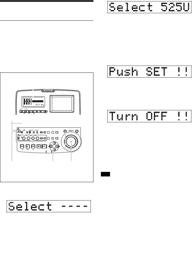
Setting procedure
Use the following procedure to set the line mode.
Time data display
DATA |
DATA |
DATA |
|
|
|
|
|
|
|
DATA |
VITC VIUB COUNTER HOLD |
|
|
||||||
|
|
|
|
|
VITC |
|
|||
|
|
|
|
|
PB NDF EXT-LK |
|
|
|
|
|
|
|
|
|
HOURS |
MINUTES |
SECONDS |
FRAMES |
|
|
|
|
|
|
DISC |
E |
|
B |
|
CH15 |
CH26 |
CH37 |
CH48 BATT |
E |
|
F |
|||
PROCESS
AUDIO |
VIDEO |
CONTROL |
|
|
|
|
|
|
|
|
INPUT CH INPUT SEL INPUT SEL |
STATUS |
CHARACTER |
LIGHT |
MONITOR |
|
|
|
|
||
WARNING |
KEY INHI |
REC INHI |
OFF ON OFF ON |
OFF L H |
|
|
|
|
||
1 |
|
|
|
|
|
|
|
|
|
|
AC power switch (rear panel) a) |
|
|||||||||
|
|
TC |
|
COUNTER |
|
SUB |
THUMB |
SHUTTLE |
JOG |
|
|
KEY INHI |
|
|
|
|
|||||
NETWORK |
ON |
INT |
PRESET |
F-RUN |
SEL |
HOLD |
CLIP |
NAIL SHIFT |
|
|
|
|
|
|
|||||||
LOCAL |
|
EXT |
|
|
|
|
|
|
|
|
ACCESS REMOTE |
OFF |
RP188 |
REGEN |
R-RUN |
|
|
CLIP |
ESSENCE |
|
|
|
|
|
|
|
|
|
MENU |
MARK |
|
|
ALL/CH-1 |
CH-2 |
CH-3 |
CH-4 |
METER |
MONITOR |
|
|
|
VARIABLE |
|
|
|
MENU |
SET |
RESET |
||
REC |
|
|
|
SEL |
SEL |
|||
PRESET |
|
|
|
|
|
|
|
|
PB |
|
|
|
|
L/ST/R |
SYSTEM |
S.SEL |
|
|
|
AUDIO |
|
|
|
|||
|
|
|
|
|
|
MENU |
MARK1 |
|
PREV |
PLAY NEXT STOP REC |
|
|
IN |
OUT |
TOP F REV |
F FWD END |
|
|
MARK2 |
|
5 |
4 |
2,3 |
a)If you are using DC power or a battery pack, connect the DC power or mount the battery pack on the battery pack shoe beforehand.
1Power the unit on.
“Select ----” appears in the time data display.
Setting |
Line mode |
|
|
525U |
525(U): NTSC (areas outside Japan) |
|
|
525J |
525(J): NTSC (Japan) |
|
|
625 |
625: PAL |
|
|
3 When the desired setting appears, release the SHUTTLE button.
“Push SET !!” appears.
To redo the selection
Repeat step 2.
4 Press the SET button.
“Turn OFF !!” appears.
5 Power the unit off, and then power it on again.
The selected line mode becomes available for use.
You can change the setting made with this procedure by using basic menu item 013 “525/625 SYSTEM SELECT.” See 7-2-2 “Basic Menu Operations” (page 94) for more information about how to make basic menu settings.
Note
The line mode is not set, or is cleared, in the following situations. Reset the line mode.
•The unit is powered off before performing step 4 in the previous procedure.
•The “RESET ALL SETUP” command in the maintenance menu (see page 112) is executed.
2 With the SHUTTLE button held down, rotate the jog dial.
When you rotate the jog dial in the forward direction, the “----” part of the display changes in the sequence 525U > 525J > 625. When you rotate it in the reverse direction, the display changes in the sequence 625 > 525J > 525U.
Settings affected by the line mode
The following settings are affected when the line mode is changed.
•Alarm message language 525(J): Japanese 525(U)/625: English
•The following menu item names, setting values, or factory default setting values
Before Using the Unit |
7 |
|
|

Item |
Item name |
Settings a) |
|
No. |
|
|
|
|
525 (U)/525 (J) |
625 |
|
|
|
||
|
|
|
|
Basic menu |
|
|
|
|
|
|
|
002 |
CHARACTER |
00 to 0A to 2A |
00 to 09 to 29 |
|
H-POSITION |
|
|
|
|
|
|
003 |
CHARACTER |
00 to 2E to 38 |
00 to 37 to 43 |
|
V-POSITION |
|
|
|
|
|
|
Extended menu |
|
|
|
|
|
|
|
601 |
VITC |
12H to 16H to |
9H to 19H to 22H |
|
POSITION |
20H |
|
|
SEL-1 |
|
|
|
|
|
|
602 |
VITC |
12H to 18H to |
9H to 21H to 22H |
|
POSITION |
20H |
|
|
SEL-2 |
|
|
|
|
|
|
628 |
DF MODE |
Item |
No item |
|
|
|
|
652 |
UMID SDI |
12 H to 17 H to |
9 H to 17 H to |
|
VANC LINE |
19 H |
18 H |
|
|
|
|
660 |
ESSENCE |
12 H to 17 H to |
9 H to 17 H to |
|
MARK SDI |
19 H |
18 H |
|
VANC LINE |
|
|
|
|
|
|
703 |
BLANK LINE |
Setting range: |
Setting range: |
|
SELECT |
ALL LINE, LINE |
ALL LINE, LINE |
|
|
12 to LINE 20 |
9, 332 to LINE |
|
|
(525(U))/LINE |
22, 335, LINE 23 |
|
|
12 to LINE 21 |
|
|
|
(525(J)) |
|
|
|
|
|
710 |
INTERNAL |
BB, CB75, |
BB, CB75, |
|
VIDEO |
CB100 |
CB100 |
|
SIGNAL |
|
|
|
GENERATOR |
|
|
|
|
|
|
713 |
VIDEO |
Item |
No item |
|
SETUP |
|
|
|
REFERENCE |
|
|
|
|
|
|
723 |
INPUT |
Setting range: |
Setting range: |
|
VIDEO |
ALL LINE, LINE |
ALL LINE, LINE |
|
BLANK |
12 to LINE 20 |
9, 332 to LINE |
|
|
|
22, 335 |
|
|
|
|
a) Underlined values are the factory defaults.
•The following video processing parameters
Parameter name |
525 (U)/525 (J) |
625 |
|
|
|
Setup level |
Item |
No item |
|
|
|
Black level |
No item |
Item |
|
|
|
8 Before Using the Unit

Overview Chapter 1
1-1Features
The PDW-R1 is a convenient, compact, and lightweight optical disc recorder. It allows you to record to optical discs, play back optical discs, and record audio and video data files transferred over the  S400 (i.LINK 1)) connector and
  (network) connector. It is ideal for field applications and for desktop viewing by journalists, producers, and other production staff.
1) i.LINK is a trademark of Sony Corporation.
The features of the PDW-R1 include the following.
MPEG IMX/DVCAM recording
The PDW-R1 offers the capability to record and play back both MPEG IMX 1) and DVCAM 1) streams. Users have the flexibility to select from these formats according to their picture-quality needs, or to match their editingformat requirements.
1) MPEG IMX and DVCAM are trademarks of Sony Corporation.
Proxy AV data
Proxy AV data is a low-resolution, MPEG-4 based version of a full-resolution MPEG IMX/DVCAM stream (a video bandwidth of 1.5 Mbps and an audio bandwidth of 64 kbps per channel). Whenever a recording is made, the unit automatically generates proxy AV data from the fullresolution data and records it on the Professional Disc. Proxy AV data is much smaller in size than the fullresolution IMX or DVCAM data. It can be transferred quickly over computer networks, easily edited in the field with laptop computers, and readily used in a wide variety of applications, such as content management on smallscale servers.
Thumbnail search operation
Simply press the THUMBNAIL button and the PDW-R1 instantly displays thumbnails on the video panel or a connected monitor. You can easily cue up the desired scene by guiding the cursor to the corresponding thumbnail and confirming your selection with the SET button.
Scene selection
You can create and play back clip lists of selected clips from the disc, arranged in any order.
One disc can store up to 99 clip lists.
Clip lists make it simple to perform offline editing in the field for later use with full-scale nonlinear editing systems (XPRI 1), etc.).
1) XPRI is a trademark of Sony Corporation.
Quick picture search by jog and shuttle dials
The PDW-R1 has jog and shuttle dials as a conventional VTR to search picture in a clip. The jog dial is for frame- by-frame search at –1 to +1 times normal speed and the shuttle dial is for high-speed search at ±20 times normal speed.
IT-friendly system
In the PDW-R1, clips are recorded as video and audio data files 1). This file-based recording system also allows material to be viewed directly on a computer linked to the unit via an i.LINK (file access mode, called FAM below) connection—in the same way that a computer reads data files on an external drive. The interfaces include the
 S400 (i.LINK) connector, supporting AV/C (Audio/ Video Control) and i.LINK (FAM) protocols, and
  (network) connector. The
  (network) connector supports MXF (Material eXchange Format) file transfer capability to exchange contents with other equipment supporting MXF.
1-1 Features |
9 |
|
|

Overview 1 Chapter
1)A clip is created every time recording is stopped.
•Video and audio data are always recorded in empty sections of the disc. Recording begins instantly, even after playback, without overwriting existing video on the disc.
•Recording is done in clip units, which makes it simple to delete a clip immediately after shooting if it is judged to be unneeded.
•During playback, thumbnail lists make it easy to identify clips. The random access nature of the media allows the NEXT and PREV buttons to jump instantly to clip start frames, making it easy to check the video and audio in the clips.
•i.LINK (FAM) or network connections make it possible to transfer clip files at high speed between this unit and remote computers.
Flexible metadata recording
XDCAM 1) can record various types of metadata together with video and audio data, such as the date and time of shooting, the cameraman, the recording method, and comments about the material. This metadata can be used in applications such as the following.
•The supplied PDZ-1 Proxy Browsing Software can be used to add titles, comments, and other text data to discs and clips.
•Computer-readable text files can be recorded on the Professional Disc, to allow systematic content management.
•The ability to search metadata for the required audio and video scenes brings greater efficiency to various stages of the video production process (editing, archiving, etc.).
1) XDCAM is a trademark of Sony Corporation.
•The output from external DV devices (VTRs, nonlinear editors, etc.) can be input to this unit and recorded on Professional Discs.
Computer access to files (file access mode)
Use of application software which supports the XDCAM series 1) enables random access to video, audio, and metadata files on Professional Discs, with the ability to display file lists and perform file-based reads and overwrites.
Files can be transferred at high speed, and thumbnail lists of disc contents can be viewed on computer screens.
1)Such software includes the supplied PDZ-1 Proxy Browsing Software and the XPRI series.
Equipped with network connector
This network connector of unit can be connected to computers and networks to enable high-speed file transfers and display of lists of the video, audio, and metadata files stored on Professional Discs. Workflows can be improved by the ability to use FTP commands to transfer files to remote locations.
Color LCD built-in
With the built-in 3.5-inch type color LCD screen, you can display contents on the disc without an external monitor.
Supports a variety of interfaces
The PDW-R1 supports a variety of interfaces and is suitable for use with various nonlinear editing systems.
Analog interfaces
Video: The unit can input and output a composite analog video signal.
Audio: The unit has two audio channels. When in 4- channel mode, you can input two channels of audio either as channels 1 and 2 or as channels 3 and 4. The two audio channels can be output also either as channels 1 and 2 or as channels 3 and 4.
Digital interfaces
SDI (Serial Digital Interface)/AES/EBU: This allows the unit to input and output D1 (component) format digital video and audio signals and also AES/EBUformat digital audio signals.
Equipped with i.LINK connector
The i.LINK connector of this unit supports the following two functions.
Input and output of DV streams (AV/C mode)
•DV streams can be output from this unit and recorded on standard DV equipment.
•During MPEG IMX playback, the playback signals can be converted and output as DV streams, allowing you to connect DV-compatible nonlinear editors.
Compact size, lightweight and batterypowered operation
The PDW-R1 is designed small and light enough to carry out to the field and it is operable with battery to work speedily in the field.
Supporting SNMP for service and maintenance
The PDW-R1 is compatible with Sony remote maintenance and monitoring software—an SNMPcompliant application that can monitor and log the hardware’s status in real time via a TCP/IP network. If a malfunction is detected, this system can immediately identify the problem, allowing you to take corrective action.
10 1-1 Features

Names and Functions of |
Chapter 2 |
Parts |
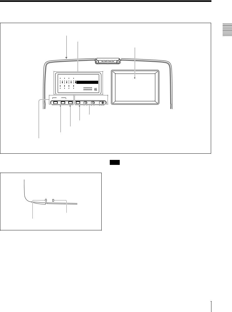
2-1 Configuration
Operation of the PDW-R1 uses the parts shown in the following figure.
Security slot
You can fit a commercially available security cable into this slot. a)
Battery pack shoe (covered)
(see page 33)
a) For information about how to use your security cable, refer to the instructions provided with the security cable.
Shoulder belt posts
(see page 134)
Carrying handle
Use this to carry the unit.
Disc slot and EJECT button
(see page 38)
Control panel (see page 12)


Built-in speaker (monaural)
AC power switch (rear panel)
Press " to power on; press a to power off.
SDI
Press here to raise the cover.
LCD panel (see page 17)
Cable clamp (see page 22)
SD |
I |
Connectors (see page 21)
2-1 Configuration 11
Parts of Functions and Names 2 Chapter
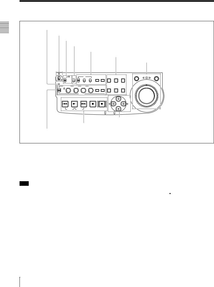
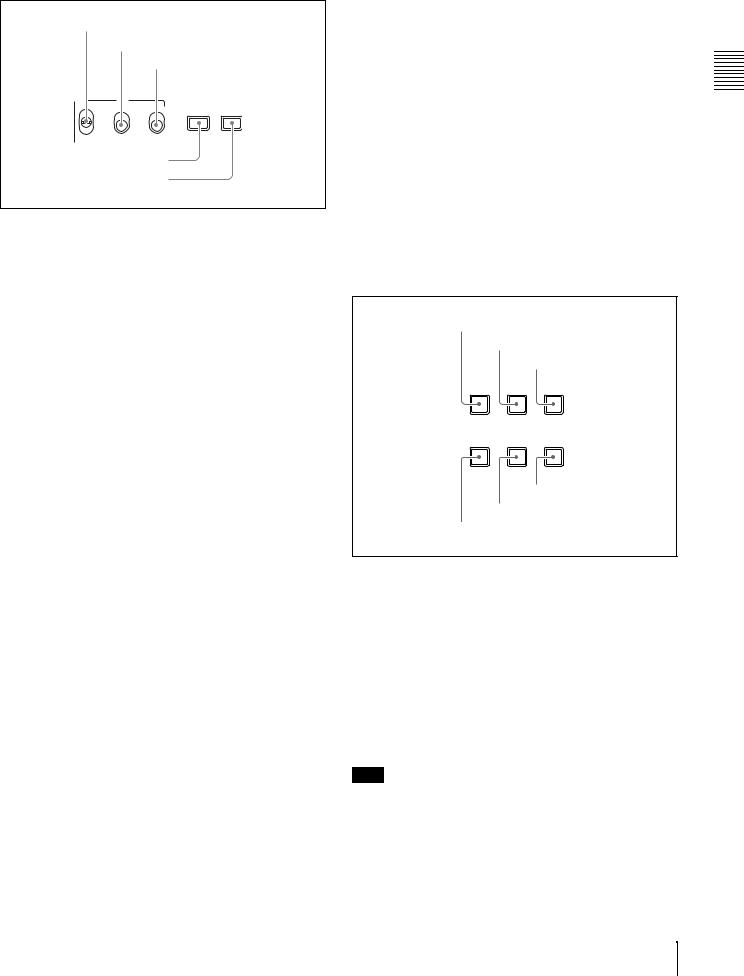
2-2 Control Panel
1 ACCESS indicator
2 On/standby switch and indicator
3 Remote control switch and NETWORK access indicator
4 KEY INHI switch
1 Time data settings section (see page 13)
2 Operating mode selection/menu setting section (see page 13)
3 Jog/shuttle control block (see page 14)
|
|
|
|
TC |
COUNTER |
|
SUB |
THUMB |
|
SHUTTLE |
JOG |
|
|
KEY INHI |
|
|
SHIFT |
|
|
||||||
|
|
|
CLIP |
NAIL |
|
|
||||||
|
NETWORK |
ON |
INT |
PRESET |
F-RUN SEL |
HOLD |
|
|
||||
|
|
|
|
|||||||||
|
LOCAL |
|
EXT |
|
|
|
|
|
|
|
|
|
ACCESS |
REMOTE |
OFF |
RP188 |
REGEN |
R-RUN |
|
|
CLIP |
ESSENCE |
|
|
|
|
|
|
|
|
|
|
|
|
|
|
||
ALL/CH-1 |
CH-2 |
CH-3 |
CH-4 |
|
|
MENU |
MARK |
|
|
|
||
METER |
MONITOR |
MENU |
SET RESET |
|
|
|||||||
VARIABLE |
|
|
|
|
|
|
|
|||||
|
|
|
|
|
SEL |
SEL |
|
|
||||
REC |
|
|
|
|
|
|
|
|||||
|
|
|
|
|
|
|
|
|
|
|
|
|
PRESET |
|
|
|
|
|
|
|
|
|
|
|
|
PB |
|
|
|
|
|
|
L/ST/R |
SYSTEM |
S.SEL |
|
|
|
|
|
|
AUDIO |
|
|
|
|
|
||||
|
|
|
|
|
|
|
|
|
||||
|
|
|
|
|
|
MENU |
MARK1 |
|
|
|||
|
|
|
|
|
|
|
|
|
|
|||
PREV |
PLAY |
NEXT |
STOP |
|
REC |
|
|
|
|
|
||
|
|
|
|
|
|
|
|
IN |
|
|
OUT |
|
TOP |
F REV |
F FWD |
END |
|
|
|
|
|
|
|
|
|
|
|
|
|
|
|
|
|
|
MARK2 |
|
|
|
6 Arrow buttons (see page 16)
5 Recording and playback control section (see page 16)
4 Audio settings section (see page 15)
a ACCESS indicator
This lights when the disc is accessed and when a file is opened by a FAM or FTP connections (see page 72).
If the on/standby switch is set to the 1 position while this indicator is lit, access to the disc is completed before the unit switches to the standby state.
Note
While the ACCESS indicator is lit, do not turn off the AC power switch, disconnect the power cord, or remove the battery. This could lead to a loss of data from the disc.
b On/standby ("/1) switch and indicator
When the AC power switch on the rear panel is in the " position, or a battery is loaded, this switches the PDW-R1 between the operating (") and standby (1) states. When the switch is moved to the " position, the indicator lights. When the switch is moved to the 1 position, the indicator goes off.
When operating the PDW-R1 from an AC power supply, normally leave the AC power switch in the " position, and switch the PDW-R1 between the operating and standby states using the on/standby switch.
cRemote control switch and NETWORK access indicator
Different positions of the switch allow different operations as follows.
NETWORK: Enables access to the network. The indicator lights when an external network device is being accessed. In this state, operation from the control panel is not possible.
LOCAL: Enables operation from the control panel. REMOTE: Enables remote control of the PDW-R1 from
a device connected to the  S400 (i.LINK) connector or REMOTE connector on the side panel.
Use extended menu item 214 “REMOTE INTERFACE” to select which of the connectors is used.
See 7-3-2 “Extended Menu Operations” (page 108) for more information about how to make extended menu settings.
d KEY INHI (key inhibit) switch
Setting this switch to ON lights the KEY INHI indicator and disables the switches and buttons that are set to “dis” with extended menu item 118 “KEY INHIBIT.”
12 2-2 Control Panel
1 Time data settings section
1 INT/EXT/RP188 switch |
|
|||
|
2 PRESET/REGEN switch |
|||
|
|
3 F-RUN/R-RUNswitch |
||
|
TC |
|
COUNTER |
|
INT |
PRESET |
F-RUN |
SEL |
HOLD |
EXT |
|
|
|
|
RP188 |
REGEN |
R-RUN |
|
|
4 COUNTER SEL button |
|
|
||
5 HOLD button |
|
|
||
a INT/EXT/RP188 (internal/external/RP188 selector) switch
Before recording time code, select the type of time code with this switch.
INT: Use time code generated internally by this unit. EXT: Use time code input from an external source. RP188: Use SMPTE RP188 LTC in an SDI signal.
b PRESET/REGEN (regeneration) switch
This switch selects whether to preset a new time code value or follow already recorded time code.
PRESET: Record time code starting with a preset initial value.
REGEN: Record time code continuous with existing time code on the disc. Regardless of the setting of the F- RUN/R-RUN switch, the unit operates in R-RUN mode.
c F-RUN/R-RUN (free run/recording run) switch
This switch selects the operating mode of the internal time code generator.
F-RUN: Time code advances regardless of the operating state of the unit. Use this setting to align the time code with real time or to synchronize the time code with external time code.
R-RUN: Time code advances only during recording. Use this setting to obtain consecutive time code on the disc.
For details, see 4-1-2 “Recording Time Code and User Bit Values” (page 44).
d COUNTER SEL button
This cycles the data displayed in the time data display through the sequence TC, UB, and COUNTER.
TC: The playback time code read by the internal time code reader, or the time code generated by the internal time code generator.
Make the TC or VITC selection in extended menu item 629 “TC SELECT.”
UB: The user bits inserted in the playback time code, or user bits generated by the internal time code generator.
Make the UB or VIUB selection in extended menu item 629 “TC SELECT.”
COUNTER: The elapsed recording/playback time (hours, minutes, seconds, frames). This can be reset by pressing the RESET button (see page 14).
The corresponding indicator above the time data display lights according to the setting.
You can also synchronize timecode with the time of the internal clock. For details, see “To set time code to the time of the internal clock” (page 45).
e HOLD button
Press this button to stop the time code generator. Also, when setting the time code or user bits to be recorded, press this button first, to hold the values.
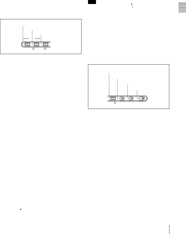
2Operating mode selection/menu setting section
1 SUBCLIP button
2 THUMBNAIL button
|
3 SHIFT button |
|
SUB |
THUMB |
SHIFT |
CLIP |
NAIL |
|
CLIP |
ESSENCE |
|
MENU |
MARK |
|
MENU |
SET |
RESET |
SYSTEM |
S.SEL |
|
MENU
6 RESET button
5 SET button
4 MENU button
a SUBCLIP button
To play back following a clip list, press this button, turning it on (see page 54). This is also effective for jog and shuttle operations.
To play clips in the order they are recorded, press this button again, turning it off.
The CLIP menu (see page 68) appears in the time data display, in the video panel, and on an external monitor when you press this button with the SHIFT button held down. Press the MENU button to escape from the CLIP menu.
Note
If no clip list is registered, this button does not light when pressed. The operation is invalid.
b THUMBNAIL button
To carry out a thumbnail search or create a clip list, press this button turning it on. Thumbnail images representing
Parts of Functions and Names 2 Chapter
2-2 Control Panel 13
Parts of Functions and Names 2 Chapter
each clip or sub-clip appear. Press once more to turn the button off, and return to a whole-screen display.
To display the thumbnails of essence mark frames (frames with an essence mark attached), hold down the SHIFT button, and press this button. The essence mark selection menu appears. Select the desired type of essence mark, and the corresponding essence mark frames appear in thumbnails. Press once more, turning the button off, to return to a whole-screen display.
c SHIFT button
Use to switch the functions of various buttons.
d MENU button
Use for setup menu and system menu operations. Pressing this button displays the setting of a setup menu item in the time data display. The same information is also superimposed on the displays of the video panel and a monitor connected to this unit (see page 94). Press once more to return to the original display. The system menu (see page 117) appears in the time data display, in the video panel, and on an external monitor, when you press this button with the SHIFT button held down. Press this button again to escape from the system menu.
e SET button
Use for setup menu settings (see page 94), scene selection (thumbnail search) settings, and so on.
The scene selection window or a menu for sub clip operations appears when you press this button with the SHIFT button held down with either of the following displayed. The window or menu appears in the video panel, and on an external monitor.
When a thumbnail screen is displayed: The scene selection window (see page 62) appears.
When a sub clip thumbnail is displayed: A sub clip operation menu (see page 64) appears.
f RESET button
Press to reset the counter. This is also used to cancel or abandon setup menu settings and scene selection (thumbnail search).
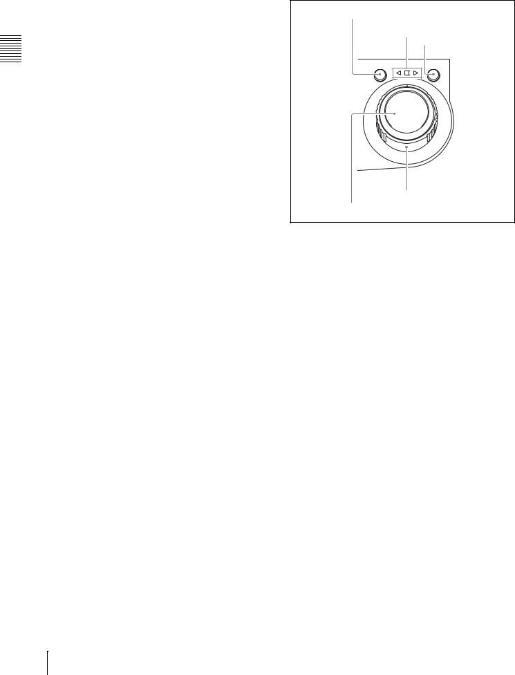
3 Jog/shuttle control block
1 SHUTTLE button
2 Jog/shuttle transport indicators
3 JOG button
SHUTTLE |
JOG |
5 Shuttle dial
4 Jog dial
For details of playback operations with these buttons and dials, see 4-2-2 “Playback Operation” on page 51.
a SHUTTLE button
To play back in shuttle mode using the shuttle dial, press this button, turning it on.
This button switches to shuttle mode whenever it is pressed, even during recording. If you do not want recording to stop with this button, set extended menu item 145 “MODE KEY ENABLE DURING RECORDING” to “stop.”
Pressing the JOG button or turning the jog dial switches to jog mode.
b Jog/shuttle transport indicators
These show the playback direction in jog or shuttle speed mode.
b (green): Lights during playback in the reverse direction. B (green): Lights during playback in the forward direction. x (red): Lights during still image display.
c JOG button
To play back in jog mode using the jog dial, press this button, turning it on.
This button switches to jog mode whenever it is pressed, even during recording. If you do not want recording to stop wih this button, set extended menu item 145 “MODE KEY ENABLE DURING RECORDING” to “stop.”
Pressing the SHUTTLE button or turning the shuttle dial switches to shuttle mode.
d Jog dial
Turn this for playback in jog mode. Turn clockwise for forward direction playback, and counterclockwise for reverse direction playback. In jog mode, the playback
14 2-2 Control Panel
speed varies in the range ±1 times normal speed, according to the rotation rate of the jog dial. There are no detents. Normally, you press the JOG button before turning the jog dial, but it is also possible to make a setting to enable jog mode directly by turning the dial (set extended menu item 101 “SELECTION FOR SEARCH DIAL ENABLE” to “dial”).
e Shuttle dial
Turn this for playback in shuttle mode. Turn clockwise for forward direction playback, and counterclockwise for reverse direction playback. In shuttle mode, the playback speed varies in the range ±20 times normal speed (using MPEG IMX/DVCAM), according to the angular position of the shuttle dial. The shuttle dial has a detent at the center position, for still image playback.
Normally, you press the SHUTTLE button before turning the shuttle dial, but it is also possible to make a setting to enable shuttle mode directly by turning the dial (set extended menu item 101 “SELECTION FOR SEARCH DIAL ENABLE” to “dial”).
Note
When extended menu item 101 “SELECTION FOR SEARCH DIAL ENABLE” is set to “dial,” after using the shuttle dial, return it to the center position. If the shuttle dial is not in the center position, it is possible occasionally for vibration from other operations to activate the dial, and start playback in shuttle mode.
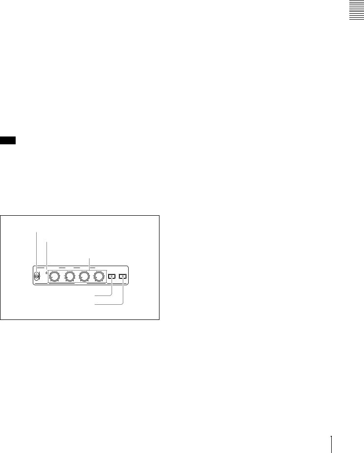
4 Audio settings section
1VARIABLE switch ALL indicator
2 ALL/CH1, CH-2 to CH4 adjustment knobs
ALL/CH-1 |
CH-2 |
CH-3 |
CH-4 |
METER |
MONITOR |
VARIABLE |
|
|
|
||
|
|
|
SEL |
SEL |
REC |
|
PRESET |
|
PB |
L/ST/R |
|
AUDIO
3 AUDIO METER SEL button
4 AUDIO MONITOR SEL button
aVARIABLE (audio level adjustment selector) switch
This selects which of the input audio and playback audio has the level adjusted by the ALL/CH-1, and CH-2 to CH- 4 adjustment knobs.
REC: Adjust the input audio levels. The playback audio levels are fixed at their preset values.
PRESET: Do not adjust the audio levels.
PB: Adjust the playback audio levels. The input audio levels are fixed at their preset values.
bALL/CH-1, CH-2 to CH-4 (audio level) adjustment knobs
Depending on the setting of the VARIABLE switch, these adjust the input audio or playback audio levels of channels 1 to 4.
By the setting of extended menu item 131 “AUDIO VOLUME,” you can enable the ALL/CH-1 knob to simultaneously adjust all eight channels. When this simultaneous adjustment is enabled the ALL indicator lights.
c AUDIO METER SEL (selection) button
When using MPEG IMX format in eight-channel mode, select whether the audio level meters should display channels 1 to 4 or channels 5 to 8.
Pressing this button toggles the selection, and the audio level meter channel display also changes.
The factory default is for channels 1 to 4 to be selected.
d AUDIO MONITOR SEL (selection) button
This button selects two channels from among the up to eight audio signal channels. You can monitor the audio of the selected channels (the left and right channels in the case of stereo output) with the PHONES jack on the front panel and the built-in speaker.
Pressing this button cycles through the following five channel combinations.
•tr1/2: Channels 1 (left) and 2 (right)
•tr3/4: Channels 3 (left) and 4 (right)
•tr5/6: Channels 5 (left) and 6 (right)
•tr7/8: Channels 7 (left) and 8 (right)
•MENU: Audio channels selected with extended menu item 837 and 838 “AUDIO MONITOR CHANNEL
ARRANGE”
The factory default is for channels 1 (left) and 2 (right) to be selected.
You can select whether to monitor both of the selected channels or only one, by pressing this button with the SHIFT button held down. Each press selects stereo, right, or left.
ST: Stereo audio is output from the PHONES jack. Monaural audio, the left and right channels mixed, is output from the built-in speaker.
R:The right channel audio is output from the PHONES jack and the built-in speaker.
L:The left channel audio is output from the PHONES jack and the built-in speaker.
Parts of Functions and Names 2 Chapter
2-2 Control Panel 15
Parts of Functions and Names 2 Chapter
5Recording and playback control section
1 PREV button
2 PLAY button
|
3 NEXT button |
PREV |
PLAY NEXT STOP REC |
TOP F REV |
F FWD END |
4 STOP button
5 REC button
a PREV (previous) button
Press this button, turning it on, to show the first frame of the current clip. While the first frame of a clip is shown, pressing this button jumps to the beginning of the previous clip.
This button is also used together with other buttons for the following operations.
Reverse direction high-speed search: Hold down the PLAY button, and press this button. A high-speed search in the reverse direction is carried out.
Displaying the first frame of the first clip: Hold down the SHIFT button, and press this button.
b PLAY (playback) button
To start playback, press this button, turning it on.
This button stops recording whenever it is pressed, even during recording. If you do not want recording to stop with this button, set extended menu item 145 “MODE KEY ENABLE DURING RECORDING” to “stop.”
c NEXT button
Press this button, turning it on, to jump to the next clip, and show the first frame.
This button is also used together with other buttons for the following operations.
Forward direction high-speed search: Hold down the PLAY button, and press this button. A high-speed search in the forward direction is carried out.
Displaying the last frame of the last clip: Hold down the SHIFT button, and press this button.
d STOP button
To stop recording or playback, press this button, turning it on. The frame at the stop point appears.
The unit enters standby off mode when you press this button with the SHIFT button held down. It returns from standby off mode to the original state when you press this button again with the SHIFT button held down. (The lit or unlit status of the STOP button does not change.)
This unit can automatically enter standby off mode whenever a specified time elapses in disc stop mode. For details, see the description of extended menu item 501 “STILL TIMER” (page 101).
e REC (record) button
To start recording, hold down this button, and press the PLAY button. The recording takes place on an unrecorded part of the disc.
To stop recording, press the STOP button. This creates a clip of the recorded portion.
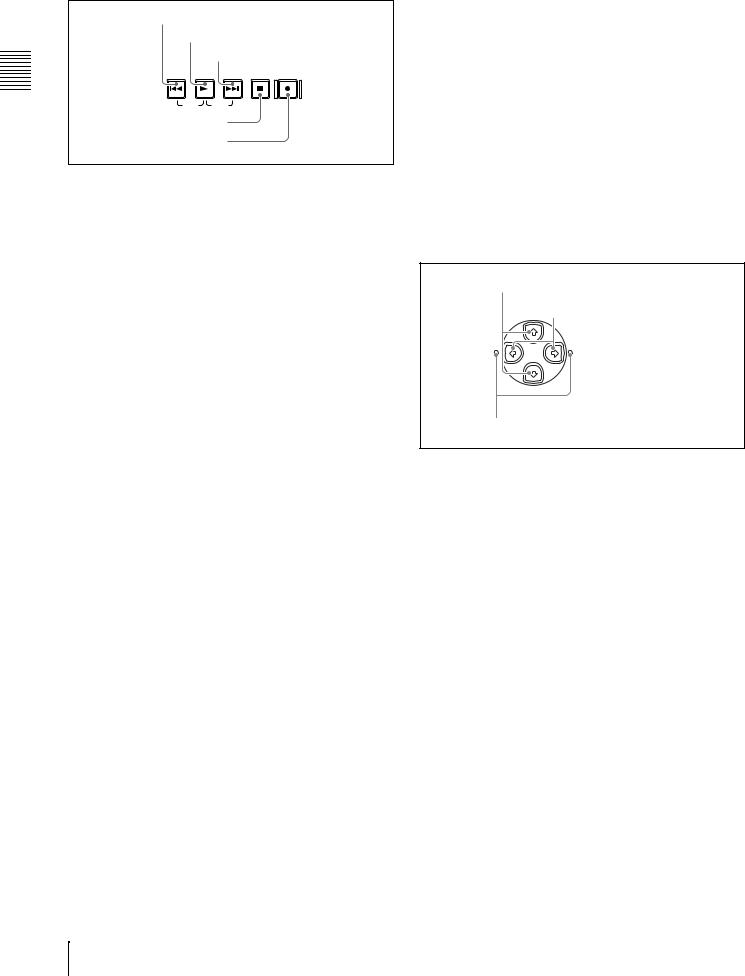
6 Arrow buttons
The four arrow buttons are also used as the MARK1 button, MARK2 button, IN button, and OUT button. The correspondence with the buttons is as follows.
F button: MARK1 button f button: MARK2 button G button: IN button
g button: OUT button
You can use these buttons for thumbnail selection, menu setting operations, setting IN/OUT points, and so on.
1 F/MARK1 button and f/MARK2 button
2 G/IN button and g/OUT MARK1 button
IN |
OUT |
MARK2
3 IN indicator and OUT indicator
a F/MARK1 button and f/MARK2 button
When the THUMBNAIL button (see page 13) is lit, you can use these for thumbnail selection.
During recording and playback, the F/MARK1 and f/ MARK2 buttons can be pressed with the SET button held down to record a shot mark 1 or shot mark 2 as an essence mark.
To delete or change essence marks, use the supplied PDZ- 1 Proxy Browsing Software.
b G/IN button and g/OUT button
When the THUMBNAIL button (see page 13) is lit, you can use these for thumbnail selection.
An In or Out point is set when you press the SET button with the G/IN or g/OUT button held down. The In or Out point setting is deleted when you press the RESET button with the G/IN or g/OUT button held down.
c IN indicator and OUT indicator
IN indicator: When an IN point is set, this lights. If an attempt is made to set the IN point after a recorded OUT point, this flashes.
OUT indicator: When an OUT point is set, this lights. If an attempt is made to set the OUT point before a recorded IN point, this flashes.
16 2-2 Control Panel
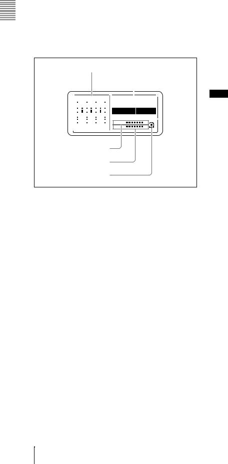
2-3 LCD Panel
1 Indicators on the back of the LCD panel
1 Status display (see page 18)
2 Video panel (color)
DATA |
DATA |
DATA |
DATA |
VITC VIUB COUNTER HOLD |
|
|
||||||||||||||||||
0 |
|
|
|
|
0 |
|
|
|
|
0 |
|
|
|
|
0 |
|
|
|
|
VITC |
|
|||
dB |
OVER |
|
dB |
OVER |
|
dB |
OVER |
|
dB |
OVER |
|
|
|
|
|
|
||||||||
-12 |
|
|
|
|
-12 |
|
|
|
|
-12 |
|
|
|
|
-12 |
|
|
|
|
PB NDF EXT-LK |
|
|
|
|
|
|
|
|
|
|
|
|
|
|
|
|
|
|
|
|
|
|
|
||||||
|
|
|
|
|
|
|
|
|
|
|
|
|
|
|
|
|
|
|
||||||
|
|
|
|
|
|
|
|
|
|
|
|
|
|
|
|
|
|
|
|
|
||||
|
|
|
|
|
|
|
|
|
|
|
|
|
|
|
|
|
|
|
|
|
||||
|
|
|
|
|
|
|
|
|
|
|
|
|
|
|
|
|
|
|
|
|
||||
|
|
|
|
|
|
|
|
|
|
|
|
|||||||||||||
-20 |
|
|
|
|
-20 |
|
|
|
|
-20 |
|
|
|
|
-20 |
|
|
|
|
HOURS |
MINUTES |
SECONDS |
FRAMES |
|
|
|
|
|
|
|
|
|
|
|
|
|
|
|
|
|
|||||||||
|
|
|
|
|
|
|
|
|
|
|
|
|
|
|
|
|||||||||
|
|
|
|
|
|
|
||||||||||||||||||
-30 |
|
|
|
|
-30 |
|
|
|
|
-30 |
|
|
|
|
-30 |
|
|
|
|
|||||
|
|
|
|
|
|
|
|
|
|
|
|
|
|
|
|
|||||||||
|
|
|
|
|
|
|
|
|
|
|
|
|
|
|
|
|||||||||
|
|
|
|
|
|
|
|
|
|
|
|
|
|
|
|
|||||||||
|
|
|
|
|
|
|
||||||||||||||||||
-40 |
|
|
|
|
-40 |
|
|
|
|
-40 |
|
|
|
|
-40 |
|
|
|
|
DISC |
E |
|
B |
|
|
|
|
|
|
|
|
|
|||||||||||||||||
-60 |
|
|
|
|
-60 |
|
|
|
|
-60 |
|
|
|
|
-60 |
|
|
|
|
|
||||
|
|
|
|
|
|
|
|
|
|
|
|
|
|
|
|
|
||||||||
|
|
|
|
|
|
|
|
|
|
|
|
|
|
|
|
|
||||||||
|
|
|
|
|
|
|
|
|||||||||||||||||
|
|
|
|
|
|
|
|
|
|
|
|
|
|
|
|
|
|
BATT |
E |
|
F |
|||
CH15 |
CH26 |
CH37 |
CH48 |
|
||||||||||||||||||||
AUDIO |
|
PROCESS |
|
|
VIDEO |
CONTROL |
LIGHT |
MONITOR |
|
INPUT CH INPUT SEL |
INPUT SEL |
STATUS CHARACTER |
WARNING |
KEY INHI |
REC INHI |
OFF |
ON |
OFF |
ON |
OFF |
L |
H |
3 Display settings section (see page 19)
5 REC INHI indicator
4 KEY INHI indicator
3 WARNING indicator
2 Audio and video settings section (see page 19)
a Indicators on the back of the LCD panel
There are two indicators, as follows.
OPERATION ACCESS
ACCESS indicator
OPERATION indicator
OPERATION indicator: Lights when the on/standby switch on the control panel is in the on (") position.
ACCESS indicator: Lights when the disc is being accessed. If the on/standby switch is set to the 1 position while this indicator is lit, access to the disc is completed before the unit switches to the standby state.
Note
While the ACCESS indicator is lit, do not turn off the AC power switch, disconnect the power cord, or remove the battery. This could lead to a loss of data from the disc.
b Video panel (color)
In recording, playback and editing operations, this shows recording and playback video, thumbnails, and other images. A status screen appears here when you press the STATUS button (see page 19).
c WARNING indicator
This lights when condensation within the PDW-R1, a laser diode fault, or another hardware error is detected. It goes off when the error state is cleared. When this indicator is lit, the time data display and video panel show an error message.
For details, see 8-3 “Error Messages” (page 121) and 8- 4 “Alarms” (page 122).
d KEY INHI (key inhibit) indicator
This lights when the KEY INHI switch is set to on, with either “MON./INPUT SEL” or “CONTROL PANEL” set to “dis” in extended menu item 118 “KEY INHIBIT.”
Parts of Functions and Names 2 Chapter
2-3 LCD Panel 17
Parts of Functions and Names 2 Chapter
e REC INHI (recording inhibit) indicator
This lights in the following cases.
•When a disc with recording inhibited is loaded.
•When extended menu item 310 “REC INHIBIT” is set to “on.”
•The format of the recorded part of the disc does not match the settings of the PDW-R1 (number of recorded channels, TV system (525/625 selection), and recording format (DVCAM/IMX50/IMX40/IMX30 selection)).
1 Status display
1 Audio level meters
2 Time data display
|
|
|
|
|
|
|
|
|
|
|
|
|
|
|
|
|
|
|
|
|
|
|
|
|
|
DATA |
DATA |
DATA |
DATA |
|
|
VITC VIUB COUNTER HOLD |
|
|
|||||||||||||||||
dB |
|
|
|
|
dB |
|
|
|
|
dB |
|
|
|
|
dB |
|
|
|
|
|
VITC |
|
|||
OVER |
OVER |
OVER |
OVER |
||||||||||||||||||||||
0 |
|
|
|
|
0 |
|
|
|
|
0 |
|
|
|
|
0 |
|
|
|
|
|
PB NDF EXT-LK |
|
|
|
|
-12 |
|
|
|
|
-12 |
|
|
|
|
-12 |
|
|
|
|
-12 |
|
|
|
|
|
|
|
|
||
|
|
|
|
|
|
|
|
|
|
|
|
|
|
|
|
|
|
|
|
||||||
|
|
|
|
|
|
|
|
|
|
|
|
|
|
|
|
|
|
|
|
|
|
||||
|
|
|
|
|
|
|
|
|
|
|
|
|
|
|
|
|
|
|
|
|
|
||||
|
|
|
|
|
|
|
|
|
|
|
|
|
|
|
|
|
|
|
|
|
|
||||
|
|
|
|
|
|
|
|
|
|
|
|
||||||||||||||
-20 |
|
|
|
|
-20 |
|
|
|
|
-20 |
|
|
|
|
-20 |
|
|
|
|
|
HOURS |
MINUTES |
SECONDS |
FRAMES |
|
|
|
|
|
|
|
|
|
|
|
|
|
|
|
|
|
|
|||||||||
|
|
|
|
|
|
|
|
|
|
|
|
|
|
|
|
|
|||||||||
|
|
|
|
|
|
|
|||||||||||||||||||
-30 |
|
|
|
|
-30 |
|
|
|
|
-30 |
|
|
|
|
-30 |
|
|
|
|
|
|||||
|
|
|
|
|
|
|
|
|
|
|
|
|
|
|
|
|
|||||||||
|
|
|
|
|
|
|
|
|
|
|
|
|
|
|
|
|
|||||||||
|
|
|
|
|
|
|
|
|
|
|
|
|
|
|
|
|
|||||||||
|
|
|
|
|
|
|
|||||||||||||||||||
-40 |
|
|
|
|
-40 |
|
|
|
|
-40 |
|
|
|
|
-40 |
|
|
|
|
|
|
|
|
|
|
-60 |
|
|
|
|
-60 |
|
|
|
|
-60 |
|
|
|
|
-60 |
|
|
|
|
|
DISC |
E |
|
B |
|
|
|
|
|
|
|
|
|
|
|
|
|
|
|
|
|
|
|
||||||||
|
|
|
|
|
|
|
|
|
|
|
|
|
|
|
|
|
|
||||||||
|
|
|
|
|
|
|
|
||||||||||||||||||
|
|
|
|
|
|
|
|
|
|
|
|
|
|
|
|
|
|
|
BATT |
E |
|
F |
|||
CH15 |
CH26 |
CH37 |
CH48 |
|
|
||||||||||||||||||||
|
|
|
|
|
|
|
|
|
|
|
|
|
|
|
|
|
|
|
|
|
|
|
|
|
|
3DISC remaining capacity indicator
4 BATT display
5 Disc loaded mark
a Audio level meters
Depending on the setting of the AUDIO METER SEL button (see page 15), these show the audio recording levels (during recording) or audio playback levels (during playback) of channels 1 to 4 or channels 5 to 8. If an audio level exceeds 0 dB, the OVER indicator lights.
The DATA indicator lights when non-audio signals are played back.
By means of a maintenance menu setting, you can display a reference level indicator (“-”) to the right of each meter when recording.
For details of the maintenace menu, see 7-4 “Maintenance Menu” on page 112.
b Time data display
Normally, this shows the disc playback time, time code, or user bit information, as selected by the COUNTER SEL button (see page 13) and extended menu item 629 “TC SELECT.”
It is also used for error messages, setup menus, and other displays.
The following indicators are located above the time data display.
COUNTER indicator: This lights when a counter value (hours, minutes, seconds, and frames, resettable) is displayed in the time data display.
HOLD indicator: This lights when the internal time code generator (TCG) is stopped. Does not light when the output of the time code reader (TCR) is being displayed during playback and stop.
TC/VITC (time code type) indicator: This lights when the COUNTER SEL button (see page 13) is set to TC. The time data display shows the time code.
When extended menu item 629 “TC SELECT” is set to “tc,” this shows “TC,” and when “vitc” is selected, it shows “VITC.”
UB/VIUB (user bit type) indicator: This lights when the COUNTER SEL button is set to UB. The time data display shows the user bits.
When extended menu item 629 “TC SELECT” is set to “tc,” this shows “UB,” and when “vitc” is selected it shows “VIUB.”
VITC indicator: This lights in the following cases.
•In playback mode, when VITC is being read. (Regardless of what the time data display is showing.)
•When VITC is being recorded, or in E-E mode 1) when VITC is recorded due to one of the following conditions.
-Extended menu item 619 “VITC” is set to “on.”
-There is VITC in the selected video input signal, and that line has been set to “thru” with extended menu item 723 “INPUT VIDEO BLANK.”
PB (playback) indicator: This lights when the output of the time code reader (TCR) is being displayed.
NDF (non-drop-frame) indicator: This lights in E-E mode when extended menu item 628 is set to “ndf,” and during playback when the clip on the disc has non- drop-frame time code.
EXT-LK (external synchronization) indicator: This lights when the internal time code generator is locked to an external signal input to the TC IN connector.
1)E-E mode: Abbreviation of Electric to Electric mode. The mode in which input video and audio signals are output after passing only through the electrical circuits.
c DISC remaining capacity indicator
This shows the amount of free capacity on the current disc, as follows.
xxxxxxx (7 segments lit): All capacity is available. As clips are recorded, the number of lit LED segments decreases.
“DISC” flashing: The disc is almost full.
“DISC” and “E” flashing: The disc is full (it must be replaced).
d BATT (battery) status display
This shows the amount of charge left in the battery, as follows.
xxxxxxx (7 segments lit): Adequately charged. As the battery discharges, the number of lit LED segments decreases.
“BATT” flashing: Almost exhausted. Operation of the PDW-R1 continues.
18 2-3 LCD Panel
“BATT” and “E” flashing: Exhausted (charging required). Operation of the PDW-R1 stops.
e Disc loaded mark 
This lights while a disc is loaded in the PDW-R1. It flashes as the disc is inserted, and while it is being ejected.
2 Audio and video settings section
1 AUDIO INPUT CH button
2 AUDIO INPUT SEL button
3 VIDEO INPUT SEL button
AUDIO |
VIDEO |
|
INPUT CH INPUT SEL INPUT SEL |
|
|
WARNING |
KEY INHI |
R |
a AUDIO INPUT CH (channel) button
This selects the channel to which the audio input signal selection applies.
Each press of this button selects the next audio input channel, in the following order.
CH1 t CH2 t CH3 t CH4
The selected channel appears in the time data display and video panel.
You can use the AUDIO INPUT SEL button to select the audio input signal for the selected channel.
When audio is in eight-channel mode
On channels 5 to 8, you can input only the audio signals embedded in an SDI signal.
b AUDIO INPUT SEL (selection) button
This selects the input signal to the channel selected with the AUDIO INPUT CH button described above.
Each press of this button selects the next audio input signal, and the audio input indications in the time data display and video panel change to reflect this. ANALOG: Analog audio signal input to the AUDIO IN
connector
SDI: SDI audio signal input to the SDI IN connector AES/EBU: AES/EBU format digital audio signal input to
the DIGITAL AUDIO (AES/EBU) IN connector SG: Audio test signal generated by the internal signal
generator
c VIDEO INPUT SEL (selection) button
Pressing this button cycles through the following selections of the video input signal.
•SDI video signal input to the SDI IN connector
•Composite video signal input to the VIDEO IN connector
•Test video signal from the internal signal generator
•i.LINK-compliant DVCAM format digital signal (i.LINK input comprising both video and audio signals) input to the  S400 (i.LINK) connector
Signals are selected in the following order. The video input indication in the video panel changes to reflect this.
SDI t COMPOSITE t SG t i.LINK
Note
Input signals (AV/C) from the  S400 (i.LINK) connector cannot be recorded when the basic menu item 031 “RECORDING FORMAT” is set to “IMX 50,” “IMX40,” or “IMX 30.” E-E video display and audio output are also not possible.
Select a signal other than “i.LINK” to record IMX format video signals. When i.LINK input signals are selected, set basic menu item 031“RECORDING FORMAT” to “DVCAM.”
See 7-2-2 “Basic Menu Operations” (page 94) for more information about how to make basic menu settings.
3 Display settings section
1 STATUS button
2 CHARACTER switch
3 LIGHT switch
|
|
|
4 MONITOR switch |
PROCESS |
|
|
|
CONTROL |
|
|
|
STATUS CHARACTER |
LIGHT |
MONITOR |
|
REC INHI |
OFF ON |
OFF ON |
OFF L H |
|
|||
a STATUS button
Displays information about the current settings of this unit in the video panel.
The displayed information changes in the following order with each press of the button.
Page 1 t Page 2 t Display off
Items displayed on page 1
Item |
Description |
|
|
525, 625 |
Line mode selected with basic menu |
|
item 013 |
|
|
IMX50, IMX40, |
Video recording format selected with |
IMX30, DVCAM |
basic menu item 031 |
|
|
8ch, 4ch |
Number of audio recording channels |
|
(When the format is IMX50/40/30, this |
|
is the number of channels specified by |
|
maintenance menu item “AUDIO |
|
CONFIG” - “DATA LENGTH.” When the |
|
format is DVCAM, this is always 4ch.) |
|
|
VIN |
The video input signal selected with the |
|
VIDEO INPUT SEL button (setting |
|
values: SDI, COMPST, SG, i.LINK) |
|
|
AINn (n: channel |
The audio input signal selected with the |
number 1 to 4) |
AUDIO INPUT SEL button (setting |
|
values: SDI, AES/EBU, SG, ANALOG) |
|
|
Parts of Functions and Names 2 Chapter
2-3 LCD Panel 19

Parts of Functions and Names 2 Chapter
Item |
Description |
|
|
PROC |
This appears when at least 1 video |
|
processing parameter has been set to |
|
“VAR (VARIABLE).” |
|
|
DISC a) |
The line mode of the current clip on the |
|
disc (setting values: 525, 625), the |
|
video recording format (setting values: |
|
IMX50, IMX40, IMX30, DVCAM), and |
|
the number of audio recording |
|
channels (setting values: 8ch, 4ch) |
|
|
RMT |
When the remote control switch is set |
|
to REMOTE, the control interface |
|
selected with extended menu item 214 |
|
(setting values: 9PIN, i.LINK, |
|
— — —) b) |
PARA |
This appears when the parallel |
|
recording with camcorder function is |
|
enabled. |
|
|
AC IN |
The type of power supplied to this unit |
DC IN ??.?V |
(AC IN: AC power, DC IN: DC power, |
BATT ??% (??.?V) |
BATT: battery pack). The voltage (units: |
|
V) appears when DC power is used, |
|
and the remaining battery charge (unit: |
|
% or V) appears when the battery pack |
|
is used. |
|
|
??MIN |
Free capacity remaining on disc (unit: |
|
minutes) |
|
|
??? |
Playback order number of clip being |
|
played back |
|
|
??h??m??s?? |
Duration of clip being played back |
|
|
a)This appears when a disc is loaded, and the format of a clip recorded on the disc is different from the format specified by basic menu item 031 or the setting of the “AUDIO CONFIG” - “DATA LENGTH” item in the maintenance menu.
b)9PIN: When extended menu item 214 is set to “9PIN”
i.LINK: When extended menu item 214 is set to “i.LINK” and menu item 215 is set to “AV/C”
—— —: When extended menu item 214 is set to “i.LINK” and menu item 215 is set to “FAM” (remote control from a device connected to the
S400 (i.LINK) connector is not possible when this combination of settings is in force)
Items displayed on page 2
Item |
Description |
|
|
VIDEO INPUT |
Same as VIN on page 1 |
|
|
AUDIO INPUT n |
Same as AINn on page 1 |
(n: channel |
|
number 1 to 4) |
|
|
|
AUDIO OUTPUT |
|
|
|
MONITOR L/R |
Audio channels selected with AUDIO |
|
MONITOR SEL button (setting values: |
|
tr1/2, tr3/4, tr5/6, tr7/8, MENU) |
|
|
(MONITOR) |
Monitor channel selected with SHIFT + |
L/ST/R |
AUDIO MONITOR SEL button (setting |
|
values: STEREO, R, L) |
|
|
ANALOG 1/2 |
Audio channels (setting values: tr1/2, |
|
tr3/4, tr5/6, tr7/8) assigned to the |
|
AUDIO OUT 1/3, 2/4 connectors with |
|
extended menu item 824 |
|
|
Item |
Description |
AES/EBU 1/2 Audio channels (setting values: tr1/2, tr3/4, tr5/6, tr7/8) assigned to the DIGITAL AUDIO (AES/EBU) OUT 1/2 connectors with sub item 1 of extended menu item 827
(AES/EBU) 3/4 Audio channels (setting values: tr1/2, tr3/4, tr5/6, tr7/8) assigned to the DIGITAL AUDIO (AES/EBU) OUT 3/4 connectors with sub item 2 of extended menu item 827
SDI/DV 1/2 |
Audio channels (setting values: tr1/2, |
|
tr3/4, tr5/6, tr7/8) assigned to channels |
|
1 and 2 of the SDI OUT (SUPER) and |
|
S400 (i.LINK) connectors with sub |
|
item 1 of extended menu item 828 |
(SDI/DV) 3/4 Audio channels (setting values: tr1/2, tr3/4, tr5/6, tr7/8) assigned to channels 3 and 4 of the SDI OUT (SUPER) and
 S400 (i.LINK) connectors with sub item 2 of extended menu item 828
When you press this button with the SHIFT button held down, the process control screen appears in the video panel. You can use this screen to adjust the following parameters.
•Video output level
•Chroma output level
•Setup/black level
•Chroma phase
•Output signal sync phase
•Output signal subcarrier phase
See “Adjusting video processing parameters” (page 49) for more information about how to make the adjustments.
b CHARACTER switch
Selects whether or not to superimpose the time code, menu settings, alarm messages, or other text information on the video signals output from the side panel SDI OUT (SUPER) and VIDEO OUT 2 (SUPER) connectors and also on the unit’s video panel.
ON: Superimpose character information.
OFF: Do not superimpose character information. The factory default setting is ON.
c LIGHT switch
Selects whether the status display backlight is on or off.
ON: On.
OFF: Off.
The factory default setting is ON.
d MONITOR switch
Selects whether to display video in the video panel. H: Display with high brightness.
L: Display with low brightness. OFF: Do not display.
The factory default setting is H.
20 2-3 LCD Panel
2-4 Connectors
Front
 1 PHONES jack and LEVEL knob
PHONES
Right side
|
2 DC OUT 12V connector |
|
|
|
|
|
|
|||
|
|
|
3 REMOTE connector |
|
|
2Analog audio signal inputs/ |
||||
|
|
|
|
|
|
|
|
|
||
|
|
|
|
4 REF VIDEO IN connector |
outputs (see page 23) |
|||||
|
|
|
|
|
|
|
1Digital audio signal |
|
||
|
|
|
|
|
|
|
inputs/outputs (see page |
DC IN |
||
|
|
|
|
|
|
|
|
|
|
12V |
|
|
|
|
|
|
|
|
|
AUDIO IN |
|
|
|
|
REMOTE |
REF VIDEO IN |
|
|
|
|
1/3 |
2/4 |
|
|
|
|
DIGITAL AUDIO (AES/EBU) |
|
|||||
|
DC OUT 12V |
|
|
IN |
1/2 |
3/4 OUT |
1/2 |
3/4 |
|
|
|
|
|
|
|
|
|
|
|
|
AC IN |
|
|
|
VIDEO |
|
|
SDI |
|
|
AUDIO OUT |
|
|
|
|
|
|
|
|
TC |
2/4 |
||
|
S400 |
IN |
OUT1 |
OUT2(SUPER) |
IN |
OUT(SUPER) |
|
IN |
1/3 |
|
|
|
OUT |
|
|||||||
|
|
|
|
|
|
|
|
|
5Time code inputs/outputs |
|
|
|
|
|
|
|
|
|
|
(see page 24) |
|
|
|
|
|
|
|
4 SDI signal inputs/outputs (see page 23) |
6Power supply |
|||
|
|
|
|
|
|
|
|
|
|
section (see |
|
|
|
3 Analog video signal inputs/outputs (see page 23) |
page 24) |
||||||
|
6 |
S400 (i.LINK) connector |
|
|
|
|
|
|
||
5 |
(network) connector |
|
|
|
|
|
|
|
||
a PHONES jack and LEVEL knob
The jack is a standard stereo jack. Connect stereo headphones with an impedance of 8 ohms, to monitor the audio during playback. (Non-audio signals are muted.) The channels monitored are selected by the AUDIO MONITOR SEL button.
Adjust the volume with the LEVEL knob. When extended menu item 820 “AUDIO OUTPUT CH1/CH2 SELECT” is set to “moni,” you can also cause this to simultaneously adjust the output volume from the AUDIO OUT 1/3 and 2/ 4 connectors on the side panel. To do this, in the setup menu, set extended menu item 114 “AUDIO MONITOR OUTPUT LEVEL” to “var.”
When no headphones are connected, you can listen to audio through the built-in speaker (monaural).
bDC OUT (DC power output) 12V connector (4-pin, female)
Supplies power to the BVR-3 Remote Control Unit (not supplied) and the RM-280 Editing Controller (not supplied). (Max. 5 W)
Note
Do not connect to any external device except those listed above.
Parts of Functions and Names 2 Chapter
2-4 Connectors 21
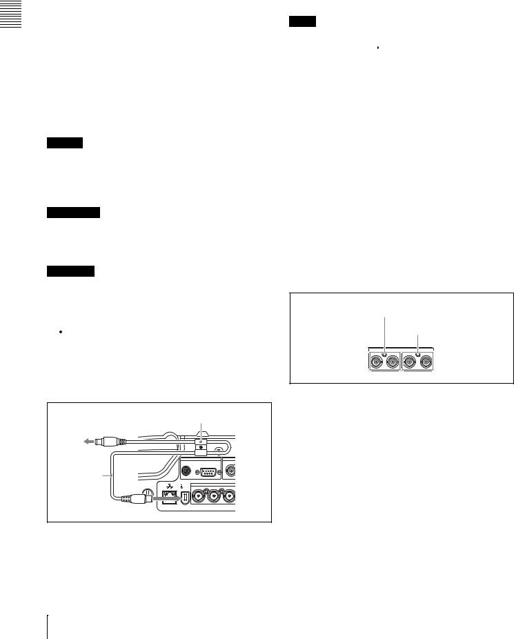
Parts of Functions and Names 2 Chapter
c REMOTE (remote control signal) connector (D- sub 9-pin)
To control the PDW-R1 from a controller or VTR supporting the RS-422A Sony 9-pin VTR protocol, connect the device to this connector.
dREF VIDEO IN (reference video signal input) connector (BNC type)
Input a reference video signal.
e 

 (network) connector (RJ-45 type)
This is a 10Base-T/100Base-TX connector for network connection.
To transfer files between an external device and the PDWR1, connect a network cable to this connector and the external device.
Caution
For safety, do not connect the connector for peripheral device wiring that might have excessive voltage to this port. Follow the instructions in this manual when making connections.
ATTENTION
Par mesure de sécurité, ne raccordez pas le connecteur pour le câblage de périphériques pouvant avoir une tension excessive à ce port. Suivez les instructions pour ce port.
ACHTUNG
Aus Sicherheitsgründen nicht mit einem PeripheriegerätAnschluss verbinden, der zu starke Spannung für diese Buchse haben könnte. Folgen Sie den Anweisungen für diese Buchse.
f S400 (i.LINK) connector (6-pin, IEEE1394 compliant)
Connect a DV device, computer, or similar, using an i.LINK cable. To prevent the connector from coming loose, we recommend that you secure the cable in the cable clamp as shown in the following figure.
To i.LINK (IEEE 1394) |
Cable clamp |
|
||
|
|
|
|
|
connector of DV device or PC |
|
|
|
|
|
DC OUT 12V |
|
|
|
i.LINK cable |
|
|
|
|
(not supplied) |
S400 |
|
VIDEO |
|
|
IN |
OUT1 |
OUT2(SUPER |
|
When the unit is shipped from the factory, the audio output signal is set to 16 bit/48 kHz/2ch mode. You can change the audio mode and output channel settings with extended
menu item 831 “DV OUT AUDIO MODE” and extended menu item 828 “SDI/DV AUDIO OUTPUT SELECT.”
See 7-3-2 “Extended Menu Operations” (page 108) for more information about how to make these settings.
Notes
•If video or audio signals from an external device
connected with the  S400 (i.LINK) connector are not output, disconnect the i.LINK cable and connect it again, pushing it straight in.
•When the PDW-R1 is connected to a device with a 6-pin i.LINK connector by an i.LINK cable, before unplugging the i.LINK cable, first power off the device and disconnect the power plug from the outlet. If the i.LINK cable is unplugged with the device power plug still connected, a current from an excessive voltage (8 to 40 V) output from the i.LINK connector of the device flows into the PDW-R1. This may cause a failure of the PDW-R1.
•When connecting the PDW-R1 to a device with a 6-pin i.LINK connector, connect to the 6-pin i.LINK connector of the other device first.
•Except in playback mode (jog and shuttle modes, etc.), if you are monitoring the audio signal output from this connector on another device, the audio signal may sound differently from the audio signal played back on the PDW-R1.
1 Digital audio signal inputs/outputs
1 DIGITAL AUDIO (AES/EBU) IN 1/2, 3/4 connectors
2 DIGITAL AUDIO (AES/EBU) OUT 1/2, 3/4 connectors
DIGITAL AUDIO (AES/EBU)
IN |
1/2 |
3/4 OUT |
1/2 |
3/4 |
aDIGITAL AUDIO (AES/EBU) IN (digital audio input) 1/2, 3/4 connectors (BNC type)
These input AES/EBU format digital audio signals. The left connector (1/2) corresponds to audio channels 1 and 2, and the right connector (3/4) corresponds to audio channels 3 and 4.
bDIGITAL AUDIO (AES/EBU) OUT (digital audio output) 1/2, 3/4 connectors (BNC type)
These output AES/EBU format digital audio signals. When the unit is shipped from the factory, the 1/2 connector is set to audio channel 1/2, and the 3/4 connector is set to audio channel 3/4. You can change these settings with extended menu item 827 “AES/EBU AUDIO OUTPUT SELECT.”
22 2-4 Connectors
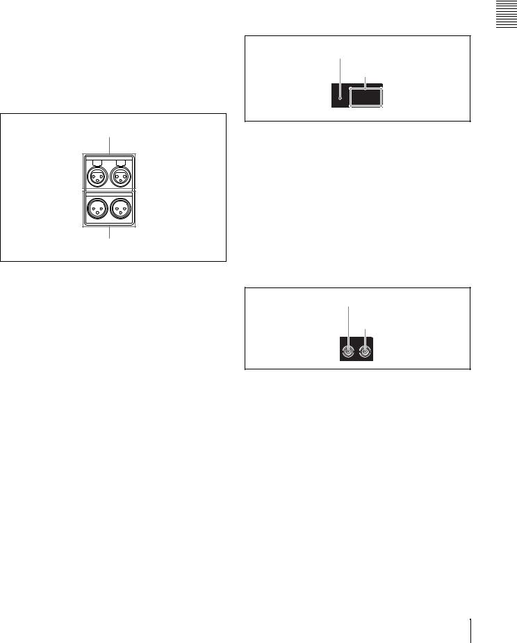
To treat the input and output signals of these connectors as non-audio signals, set the maintenance menu item “AUDIO CONFIG”-“NON-AUDIO INPUT” (recording) and extended menu item 823 “NON-AUDIO FLAG PB” (playback).
See 7-3-2 “Extended Menu Operations” (page 108) for more information about how to make extended menu settings.
See 7-4-2 “Maintenance Menu Operations” (page 114) for more information about how to make maintenance menu settings.
2 Analog audio signal inputs/outputs
1 AUDIO IN 1/3, 2/4 connectors
AUDIO IN
1/3 2/4
AUDIO OUT
1/3 2/4
2 AUDIO OUT 1/3, 2/4 connectors
aAUDIO IN (analog audio signal input) 1/3, 2/4 connectors (XLR 3-pin, female)
These input analog audio signals.
With the AUDIO INPUT SEL button (see page 19), you can select whether the signal input to connector 1/3 is assigned to audio channel 1or 3, and whether the signal input to connector 2/4 is assigned to audio channel 2 or 4. You can set the reference input level with the maintenance menu item “AUDIO CONFIG.” (Factory default setting: +4 dB)
For details of the maintenace menu, see 7-4 “Maintenance Menu” on page 112.
bAUDIO OUT (analog audio signal output) 1/3, 2/4 connectors (XLR 3-pin, male)
These output analog audio signals.
When the unit is shipped from the factory, the 1/3 connector is set to audio channel 1, and the 2/4 connector is set to audio channel 2. You can change these settings with extended menu item 824 “ANALOG LINE OUTPUT SELECT.”
You can set the output level with the maintenance menu item “AUDIO CONFIG.” (Factory default setting: +4 dB) Non-audio signals are muted.
You can also output audio monitor signals by setting extended menu item 820 “AUDIO OUTPUT CH1/CH2 SELECT” to “moni.”
See 7-3-2 “Extended Menu Operations” (page 108) for more information about how to make these settings.
For details of the maintenace menu, see 7-4 “Maintenance Menu” on page 112.
3 Analog video signal inputs/outputs
1 VIDEO IN connector
2 VIDEO OUT 1, OUT 2 (SUPER) connectors
VIDEO
IN |
OUT1 |
OUT2(SUPER) |
aVIDEO IN (analog video input) connector (BNC type)
This inputs a composite video signal.
bVIDEO OUT 1, OUT 2 (SUPER) (analog video output 1, output 2 (superimpose)) connector (BNC
type)
These output composite video signals.
The output from the VIDEO OUT 2 (SUPER) connector can have time code, menu settings, alarm messages, and other text information superimposed.
4 SDI signal inputs/outputs
1 SDI IN connector
2 SDI OUT (SUPER) connector
|
SDI |
IN |
OUT(SUPER) |
a SDI IN (SDI signal input) connector (BNC type)
This inputs an SDI format video/audio signal.
bSDI OUT (SUPER) (SDI signal output (superimpose)) connector (BNC type)
This outputs an SDI format video/audio signal.
When the unit is shipped from the factory, audio signal output is 8 channels with no switching, and RP188 time code output is set to on. You can change these settings with extended menu item 828 “SDI/DV AUDIO OUTPUT SELECT” and extended menu item 920 “SD-SDI H-ANC CONTROL.”
The output can have time code, menu settings, alarm messages, and other text information superimposed. To turn superimposition off, set the maintenance menu item “OTHERS”-“SDI SUPER” to “OFF.”
To treat the input and output signals of these connectors as non-audio signals, set the maintenance menu item
Parts of Functions and Names 2 Chapter
2-4 Connectors 23
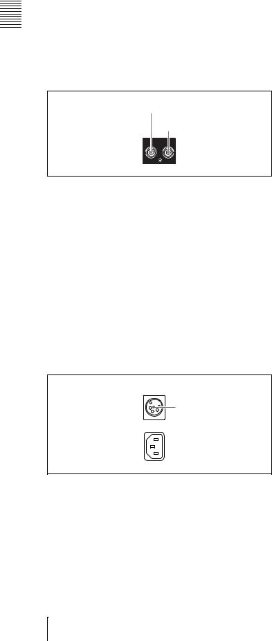
Parts of Functions and Names 2 Chapter
“AUDIO CONFIG”-“NON-AUDIO INPUT” (recording) and extended menu item 823 “NON-AUDIO FLAG PB” (playback).
See 7-3-2 “Extended Menu Operations” (page 108) for more information about how to make extended menu settings.
See 7-4-2 “Maintenance Menu Operations” (page 114) for more information about how to make maintenance menu settings.
5 Time code inputs/outputs
1 TC IN connector
2 TC OUT connector
|
TC |
IN |
OUT |
a TC IN connector (BNC type)
This inputs an SMPTE time code generated by an external device.
b TC OUT connector (BNC type)
This outputs the following time code, depending on the operating state of the PDW-R1.
During playback: playback time code
During recording: the time code from the internal time code generator or the time code input to the TC IN connector.
When extended menu item 611 “TC OUTPUT PHASE IN EE MODE” is set to “muting,” no time code is output.
6 Power supply section
DC IN 12V
1 DC IN 12V connector
 AC IN
AC IN
 2 -AC IN connector
a DC IN (DC power input) 12V connector (XLR type, 4-pin, male)
Connect DC power to this connector.
b -AC IN (AC power input) connector
Connect to an AC power supply, using an optional power cord (see page 133).
24 2-4 Connectors
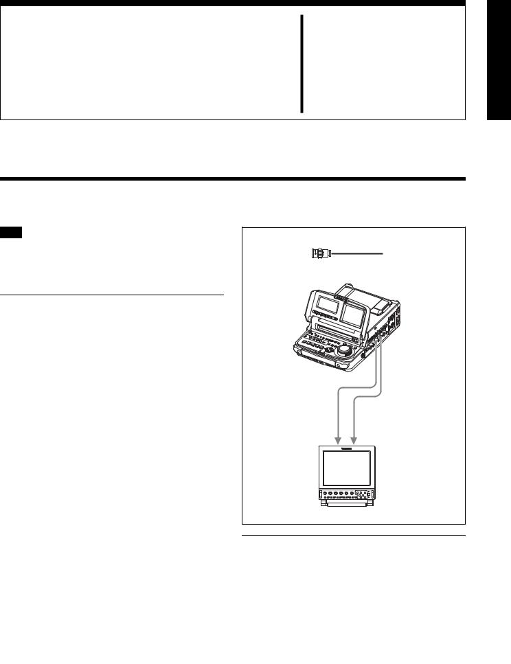
Preparations Chapter 3
3-1 Connections and Settings
Note
Production of some of the peripherals and related devices described in this chapter has been discontinued. For advice about choosing devices, please contact your Sony dealer or a Sony sales representative.
3-1-1 Connecting an External
Monitor
Connecting a Sony LCD monitor to the VIDEO OUT 1, VIDEO OUT 2 (SUPER), or SDI OUT (SUPER) connector of this unit enables you to see the output video on the monitor screen.
To superimpose text information, for example, time code and alarm messages, use the VIDEO OUT 2 (SUPER) or SDI OUT (SUPER) connector. You can select the kind of text information to display using basic menu item 005 “DISPLAY INFORMATION SELECT.”
For detailed information about basic menu items and how to make menu settings, see 7-2 “Basic Setup Menu” on page 90.
Connect a video monitor as example 1or 2shown in the following figure.
1, 2: 75 Ω coaxial cable (not supplied)
PDW-R1
SDI OUT (SUPER)
VIDEO OUT 2 (SUPER)
12
To LINE A/B connector |
To SDI IN-1/IN-2 connector |
LMD-9030 LCD monitor
3-1-2 Connections for Using PDZ-1 Proxy Browsing Software
Using the supplied PDZ-1 Proxy Browsing Software, you can carry out simple editing with proxy AV data.
For an overview of PDZ-1 and how to install the software, see 5-4 “Using PDZ-1 Proxy Browsing Software” on page
3-1 Connections and Settings |
25 |
|
|
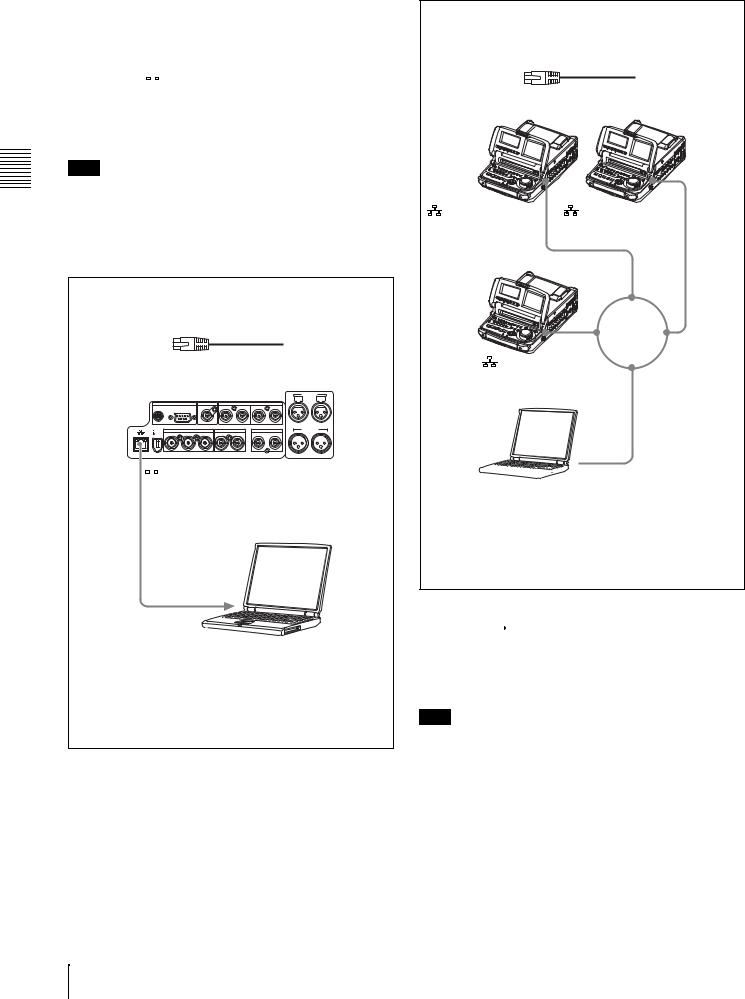
Preparations 3 Chapter
71.
For information about how to use the software, refer to the Help provided in the software.
Using the  (network) connector (FTP connection)
The following shows an example of an FTP (File Transfer Protocol) connection.
Note
To use PDZ-1 requires the PDW-R1 IP address and other network-related settings to be made beforehand.
For details of the network-related settings, see “To change network settings” (page 115).
Connecting this unit directly to a laptop computer
1: Network cable (not supplied) a)
|
|
|
PDW-R1 |
|
AUDIO IN |
|
||
|
|
REMOTE |
REF VIDEO IN |
|
DIGITAL AUDIO (AES/EBU) |
1/3 |
2/4 |
|
|
|
|
|
|
||||
DC OUT 12V |
|
|
|
IN 1/2 |
3/4 OUT |
1/2 |
3/4 |
|
|
|
VIDEO |
|
SDI |
|
TC |
AUDIO OUT |
|
|
|
|
|
1/3 |
2/4 |
|||
S400 |
IN |
OUT1 |
OUT2(SUPER) |
IN |
OUT(SUPER) |
IN |
OUT |
|
 (network) connector
1
To network connector
Laptop computer
Make sure the remote control switch (see page 12) is set to “NETWORK” and extended menu item 257 “NETWORK ENABLE” is set to “net.”
a) Use a cross cable.
Connecting three PDW-R1 units to a laptop computer via a LAN.
1: Network cable (not supplied) a)
PDW-R1 PDW-R1
(network) connector |
(network) connector |
1 |
|
PDW-R1 |
|
|
1 |
1 |
LAN |
|
|
(network) connector |
|
1

 To network connector
Laptop computer
Make sure the remote control switch (see page 12) is set to “NETWORK” on each of the three PDW-R1 units and extended menu item 257 “NETWORK ENABLE” is set to “net.”
a) Use a straight cable.
Using the  S400 (i.LINK) connector (FAM connection)
The following shows an example of a FAM (file access mode) connection.
Note
The PDZ-1 Proxy Browsing Software must be installed in advance.
The required FAM driver is also installed when you install the PDZ-1 software.
See 5-4 “Using PDZ-1 Proxy Browsing Software” (page 71) for more information about installing the PDZ-1 software.
Some limitations apply to FAM connections. For details, see 6-2 “File Access Mode File Operations” (page 78).
26 3-1 Connections and Settings
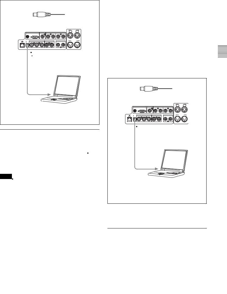
1: i.LINK cable (not supplied)
|
|
|
PDW-R1 |
|
AUDIO IN |
|
||
|
|
REMOTE |
REF VIDEO IN |
|
DIGITAL AUDIO (AES/EBU) |
1/3 |
2/4 |
|
|
|
|
|
|
||||
DC OUT 12V |
|
|
|
IN 1/2 |
3/4 OUT |
1/2 |
3/4 |
|
|
|
VIDEO |
|
SDI |
|
TC |
AUDIO OUT |
|
|
|
|
|
1/3 |
2/4 |
|||
S400 |
IN |
OUT1 |
OUT2(SUPER) |
IN |
OUT(SUPER) |
IN |
OUT |
|
 S400 (i.LINK)
1
To i.LINK (IEEE1394) 


 connector
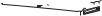
Laptop computer
Make sure extended menu item 215 “i.LINK MODE” is set to “FAM (PC REMOTE).”
3-1-3 Connecting to a Nonlinear Editing System
You can send video/audio signals (AV/C data) from this unit to a nonlinear editing system connected to the  S400 (i.LINK) connector.
The following figure shows an example connection.
Notes
•The  S400 (i.LINK) connector of this unit outputs video/audio signals in DVCAM format. Data recorded in MPEG IMX format is output after being converted into DVCAM format.
•The nonlinear editing system to be used being connected to this unit requires editing software (not supplied) supporting DVCAM format.
•Make the following settings before transferring video/ audio signals (AV/C data) from this unit to a nonlinear editing system.
Audio mode selection
Use extended menu item 831 “DV OUT AUDIO MODE” to select either of the following.
4ch: 12 bit/32 kHz/4ch
2ch: 16 bit/48 kHz/2ch (Factory default setting)
Audio output channel selection
Select the audio output channels with extended menu item 828 “SDI/DV AUDIO OUTPUT SELECT.”
For information about how to make extended menu item settings, see 7-3-2 “Extended Menu Operations” on page 108.
1: i.LINK cable (not supplied)
|
|
|
PDW-R1 |
|
AUDIO IN |
|
||
|
|
REMOTE |
REF VIDEO IN |
|
DIGITAL AUDIO (AES/EBU) |
1/3 |
2/4 |
|
|
|
|
|
|
||||
DC OUT 12V |
|
|
|
IN 1/2 |
3/4 OUT |
1/2 |
3/4 |
|
|
|
VIDEO |
|
SDI |
|
TC |
AUDIO OUT |
|
|
|
|
|
1/3 |
2/4 |
|||
S400 |
IN |
OUT1 |
OUT2(SUPER) |
IN |
OUT(SUPER) |
IN |
OUT |
|
 S400 (i.LINK)
1
To i.LINK(IEEE1394) 


 connector
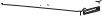
Laptop computer
(With editing software supporting DVCAM format installed)
Make sure extended menu item 215 “i.LINK MODE” is set to “AV/C.”
For the method of transferring video/audio signals (AV/C data) to a nonlinear editing system, refer to the manual provided with the editing software to be used.
3-1-4 Connections for Recording in Parallel With a Camcorder
You can start and stop recording on this unit at the same time that recording starts and stops on a camcorder. This allows you to make a backup recording of the video and audio shot by the camcorder. The following figure shows an example of the connections to make.
Preparations 3 Chapter
3-1 Connections and Settings |
27 |
|
|
Preparations 3 Chapter
1: i.LINK cable (not supplied)
DSR-400/400P/450WS/450WSP
 (i.LINK) DV OUT
PDW-R1
1
 S400 (i.LINK)
DSR-400/400P/450WS/450WSP settings
REC TRIGGER switch: INT ONLY
“REC FORMAT” on the VTR MODE page of the MAINTENANCE menu: DVCAM
PDW-R1 settings
Remote control switch (see page 12): REMOTE VIDEO INPUT SEL button (see page 19): select i.LINK
Basic menu item 031 “RECORDING FORMAT”: DVCAM Extended menu item 214 “REMOTE INTERFACE”: i.LINK Extended menu item 215 “i.LINK MODE”: AV/C
Extended menu item 216 “PARALLEL RECORDING MODE”: on
28 3-1 Connections and Settings

3-1-5 Connections for Cut Editing
By connecting this unit to a VTR (for example, MSWM2000/M2000P or DSR-2000/2000P) and an editing control unit, you can make up a cut editing system. Some example connections are shown in the following.
When using an editing control unit
When making the connections, also refer to the manuals provided with the equipment to be connected.
See page 32 for more information about editing control unit settings.
Cut editing system comprising this unit as a player, an MSW-M2000/M2000P unit as a recorder, and a BVE-700 editing control unit.
|
|
|
|
|
|
|
|
1: 75 Ω coaxial cable (not supplied) |
|
|
|
|
|
|
|
|
|
2: 9-pin remote control cable (not supplied) |
|
|
|
|
|
|
|
|
|
3: Cable with XLR connectors (not supplied) a) |
|
Video monitor |
|
|
|
|
|
|
|
Video monitor |
|
|
|
|
To analog audio input connector |
|
|
||||
|
|
|
|
|
|
|
|
To composite video input connector |
|
|
|
To composite video |
3 |
1 |
|
||||
|
1 |
input connector |
|
|
1 |
|
|||
|
|
|
|
|
|
|
|
|
|
|
|
|
|
|
|
|
|
1 |
|
|
|
|
|
|
|
|
|
REF. VIDEO |
|
|
|
|
|
|
|
|
|
INPUT |
SDI INPUT |
REF VIDEO |
VIDEO OUT 2 |
|
|
|
|
||||
IN |
|
(SUPER) |
AUDIO IN |
|
|
|
|
||
REMOTE |
REF VIDEO IN |
DIGITAL AUDIO (AES/EBU) |
|
1/3 |
2/4 |
|
|
|
|
|
|
|
|
|
|
||||
DC OUT 12V |
IN 1/2 |
3/4 |
OUT 1/2 |
3/4 |
|
|
|
|
|
VIDEO |
SDI |
|
TC |
|
AUDIO OUT |
|
AUDIO |
|
|
|
|
1/3 |
2/4 |
OUT |
|
|
|||
S400 IN OUT1 |
OUT2(SUPER) IN |
OUT(SUPER) |
IN |
OUT |
|
|
|
||
|
|
|
|
|
|||||
REMOTE |
SDI OUT (SUPER) |
PDW-R1 (player)
2
RECORDER
PLAYER-1
BVE-700
Reference video signal
PDW-R1 (player) settings
Remote control switch (see page 12): REMOTE Extended menu item 214 “REMOTE INTERFACE”: 9PIN
Extended menu item 820 “AUDIO OUTPUT CH1/CH2 SELECT”: moni
a) Use an XLR/pin converter plug (not supplied) as required.
COMPOSITE VIDEO |
REMOTE 1 IN (9P) |
MSW-M2000/M2000P |
|
OUTPUT 3 (SUPER) |
(recorder) |
2 |
|
1
 AC IN
AC IN
REF VIDEO IN
MSW-M2000/M2000P (recorder) settings
REMOTE 1(9P) button: Lit
For details about the settings of the MSW-M2000/M2000P, refer to the operation manual for the unit.
Preparations 3 Chapter
3-1 Connections and Settings |
29 |
|
|
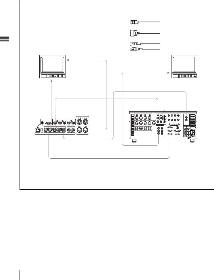
Preparations 3 Chapter
When using the editing functions of the recorder
Connections using the REMOTE connector (D-sub 9-pin):
Cut editing system comprising this unit as a player and an MSWM2000/M2000P unit as a recorder. For cut editing, the system uses the editing functions of the recorder.
Video monitor
To analog audio input connector
3 1
To composite video 1 input connector
1: 75 Ω coaxial cable (not supplied)
2: 9-pin remote control cable (not supplied)
3: Cable with XLR connectors (not supplied) a)
Video monitor
To composite video input connector
1
1Reference video signal
VIDEO |
REF VIDEO |
|
|
|
||
OUT 2 |
|
|
|
|||
(SUPER) |
IN |
|
|
AUDIO IN |
|
|
REMOTE |
REF VIDEO IN |
DIGITAL AUDIO (AES/EBU) |
1/3 |
2/4 |
|
|
|
|
|
||||
DC OUT 12V |
IN 1/2 |
3/4 |
OUT 1/2 |
3/4 |
|
|
VIDEO |
SDI |
|
TC |
AUDIO OUT |
|
AUDIO |
S400 IN OUT1 |
OUT2(SUPER) IN |
OUT(SUPER) |
IN |
1/3 |
2/4 |
OUT |
OUT |
|
|
||||
REMOTE |
|
SDI OUT (SUPER) |
|
|||
PDW-R1 (player)
2
PDW-R1 (player) settings
Remote control switch (see page 12): REMOTE Extended menu item 214 “REMOTE INTERFACE”: 9PIN
Extended menu item 820 “AUDIO OUTPUT CH1/CH2 SELECT”: moni
a) Use an XLR/pin converter plug (not supplied) as required.
REF. VIDEO |
|
INPUT |
SDI INPUT |
REMOTE 1 OUT (9P)
COMPOSITE VIDEO |
MSW-M2000/M2000P |
|
OUTPUT 3 (SUPER) |
||
(recorder) |
||
|
MSW-M2000/M2000P (recorder) settings
REMOTE 1(9P) button: Unlit
For details about the settings of the MSW-M2000/M2000P, refer to the operation manual for the unit.
30 3-1 Connections and Settings
 Loading...