


PMW-F5
Table of contents
 Loading...
4-459-611-11(1)
Solid-State Memory
Camcorder
PMW-F55
PMW-F5
Operating Instructions
Before operating the unit, please read this manual thoroughly
and retain it for future reference.
© 2013 Sony Corporation

Table of Contents
Overview
Preparations
Features ...................................................................................... 6
System Configuration ............................................................... 8
Location and Function of Parts ............................................... 9
On-Screen Indications ............................................................ 15
Sub Display Screen ...................................................... 15
LCD Monitor/Viewfinder Screen ................................ 17
Power Supply ........................................................................... 19
Using a Battery Pack .................................................... 19
Using AC Power (DC IN Power) ................................. 20
Setting the Clock ..................................................................... 20
Attaching Optional Devices .................................................... 21
Attaching a Lens .......................................................... 21
Attaching a Viewfinder ................................................ 22
Setting the Basic Action .......................................................... 23
Shooting Mode ............................................................. 23
Main Recorded Signal .................................................. 23
Color Space .................................................................. 24
Using SxS Memory Cards ...................................................... 24
About SxS Memory Cards ........................................... 24
Inserting an SxS Memory Card .................................... 24
Removing an SxS memory card ................................... 25
Switching Between SxS Memory Cards ...................... 25
Formatting an SxS Memory Card ................................ 25
Checking the Remaining Time Available for
Recording ............................................................... 25
Restoring an SxS Memory Card .................................. 26
Using an SD card ..................................................................... 27
Usable SD Cards .......................................................... 27
Inserting an SD Card .................................................... 27
Removing an SD memory card .................................... 27
Formatting an SD Memory Card .................................. 27
Checking the Remaining Time ..................................... 27
Table of Contents
2

Recording
Using an AXS-R5 .................................................................... 28
Attaching the AXS-R5 ................................................. 28
Removing the AXS-R5 ................................................ 28
Inserting an AXS Memory Card .................................. 28
Removing an AXS Memory Card ................................ 28
Recording to an AXS Memory Card ............................ 29
Formatting an AXS Memory Card ............................... 29
Checking the Remaining Time Available for
Recording ............................................................... 29
Restoring the AXS Memory Card ................................ 29
Basic Operation Procedure .................................................... 30
Changing Basic Settings ......................................................... 31
System Frequency ........................................................ 31
Recording Format ......................................................... 31
Electronic Shutter ......................................................... 31
Sensitivity/Gain/Color Temperature/
White Balance ........................................................ 32
Audio ............................................................................ 32
Time Data ..................................................................... 32
Useful Functions ...................................................................... 33
Assignable Buttons ....................................................... 33
Slow & Quick Motion .................................................. 33
Simultaneously Recording ........................................... 33
Thumbnail Screens
Thumbnail Screens ................................................................. 34
Configuration of the Screen ......................................... 34
Playing Clips ............................................................................ 35
Playing the Selected and Subsequent Clips in
Sequence ................................................................ 35
Clip Operations ....................................................................... 35
Operations of the Thumbnail Menu ............................. 35
Displaying the Detailed Information of a Clip ............. 36
Copying MPEG2 Proxy Data (PMW-F55 only) .......... 36
Deleting Clips ............................................................... 36
Changing Information on the Thumbnail Screen ......... 37
Table of Contents
3

Settings
Sub Display Operation ........................................................... 38
Sub Display Setting Items ...................................................... 39
Setup Menu Operations .......................................................... 40
Setup Menu List ...................................................................... 41
External Devices Connection
Connecting External Monitors and Recording Devices ...... 60
Operating Clips With a Computer ........................................ 61
External Synchronization ....................................................... 62
CAMERA Screen ......................................................... 39
Camera Menu ............................................................... 41
Paint Menu ................................................................... 45
Audio Menu ................................................................. 49
Video Menu .................................................................. 50
VF Menu ...................................................................... 51
TC/UB Menu ................................................................ 54
Recording Menu ........................................................... 54
Media Menu ................................................................. 55
File Menu ..................................................................... 55
Maintenance Menu ....................................................... 56
System Menu ................................................................ 57
Table of Contents
4

Appendices
Important Notes on Operation .............................................. 63
Formats and Limitations of Outputs .................................... 65
Video Formats and Output Signals .............................. 65
Error/Warning Indications .................................................... 68
Error Indications ........................................................... 68
Warning Indications ..................................................... 68
Licenses .................................................................................... 71
MPEG-2 Video Patent Portfolio License ..................... 71
On accessing software to which the GPL/LGPL
applies .................................................................... 71
Open software licenses ................................................. 71
Specifications ........................................................................... 72
General ......................................................................... 72
Camera Section ............................................................ 73
Input/Output ................................................................. 73
Media ............................................................................ 74
Package Configuration ................................................. 74
Optional Accessories .................................................... 75
Index ......................................................................................... 78
Table of Contents
5

Overview
Overview
Features
The PMW-F55/F5 is a highly compact,
lightweight and high-performance CineAlta 4K
camera with a 4K Super 35mm equivalent Singlechip CMOS image sensor.
The PMW-F55’s CMOS image sensor with
global shutter function allows you to shoot clear
4K images without rolling shutter distortion or
flash band phenomenon for perfect HD recording
performance.
The PMW-F5’s 4K image sensor allows you to
record high quality HD pictures.
You can record in MPEG2 HD video format, in
addition to the new 4K-compatible format,
XAVC, by using an SxS memory card.
4K RAW data can be recorded by using the
portable recorder, AXS-R5, which adopts the
newly developed access memory card (AXSM).
The camcorder adopts the same native FZ mount
used by the PMW-F3. You can use a variety of
cine lenses (PL mount) so that the PL/FZ
conversion adaptor comes standard.
Compatible with multi format
The camcorder is compatible with the new
format, XAVC (official name: MPEG4 AVC/
H.264 Hi422 Profiles/Level 5.2), and can record
4K: 4096 × 2160, HD: 1920 × 1080.
The camcorder is also compatible with frame
rates from 23.98P to 59.94P. For high-speed
shooting, you can record 1 fps to 60 fps for
XAVC HD recording in the S & Q mode. The
recommended media for XAVC recording is the
newly developed SxS PRO+ memory card.
The camcorder is also compatible with MPEG2
HD 422, adopted for XDCAM, and your existing
workflow can be used.
Modular structure
The camcorder is a modular design that allows
you to configure the camcorder according to
shooting circumstances, whether for cinema
production, drama, commercials, 3D shooting,
documentary filming, int erviews, etc. The handle,
viewfinder, audio connector panel, and portable
recorder can be removed according to shooting
requirements. The body and handle of the
camcorder have multiple 1/4” and 3/8” mount
points, you can attach the standard accessories
easily.
High camera technology
4K Super 35mm equivalent CMOS image sensor
The camcorder has a 4K Super 35mm equivalent
Single-chip CMOS image sensor of 11,600,000
pixels, with effective pixels count of 8,900,000,
for 4K/HD recording.
The CMOS image sensor of the PMW-F55
includes a global shutter function that allows you
to shoot clear images without rolling shutter
distortion or flash band phenomenon that occurs
with a traditional film camera. The camcorder
adopts a color filter that emphasizes color
reproduction compatible with wide color area
(exceeding that of color film), allowing for near
human vision image representation capability.
Wide latitude, low noise
The camcorder has a 14-stop latitude that can
reproduce images captured by the CMOS sensor
with smooth gradation of black to white.
Exmor Super35 CMOS technology provides low
noise levels, even with 4K resolution and 14-stop
latitude maintained.
Video signal processing
4K/HD simultaneous recording and high-speed
recording with unlimited recording time is
possible with single LSI chip processing of both
camera signals and baseband video signals.
Single-chip design provides stable, high-speed
4K 59.94P baseband video processing, low power
consumption, and compact design.
6
Features

Intuitive user interface
This camcorder has the color LCD panel on the
inside panel, and direct access menu that assigns
the commonly-used settings to 6 buttons.
Displaying the setting information large, makes
visibility better.
By switching two screens (CAMERA, VIEW),
you can perform setting speedy.
A LOCK switch allows you to prevent changing
settings by accident.
Assignable buttons
The inside panel has three assignable buttons,
while the outside panel has one assignable button.
You can operate the camcorder easily by
assigning commonly-used functions to these
buttons.
Various input/output connectors
Four types of SDI output
The camcorder has four types of SDI output that
allows you to output 4K 59.94P signal as four 3GSDI.
The four SDI outputs are assignable as SDI-1/2
OUT to Main, and SDI-3/4 OUT to Sub.
The camcorder also includes connections for
Genlock IN, Timecode IN/OUT, HDMI OUT,
Remote.
Overview
Built-in ND filter
A rotary ND filter is built into the camcorder, and
supports three types of filter: Clear, 0.9 (1/8), and
1.8 (1/64). This allows light adjustment without
the need for external matte box.
Features
7
Overview
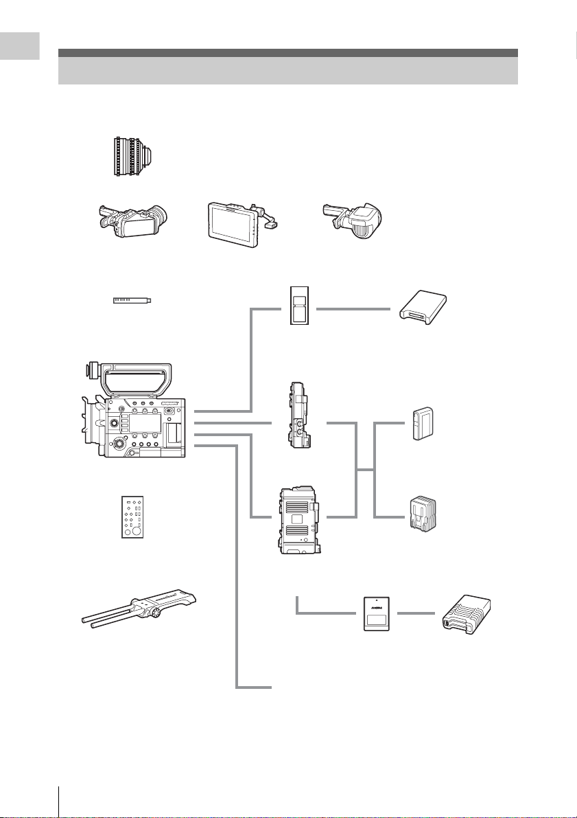
System Configuration
This section shows examples of the camera system configuration.
Lenses
SCL-P35T20, SCL-P50T20, SCL-P85T20
SCL-PK6 (set of 6 lenses)
SCL-P20T20/P25T20/P35T20A/P50T20A/P85T20A/P135T20
SCL-P11X15
Viewfinder
DVF-L350
Microphone
ECM-680S (EC-0.5X5F3M),
ECM-678, ECM-674
PMW-F55, PMW-F5
Remote control unit
RM-B170, RM-B750
Shoulder adaptor
VCT-FSA5
Viewfinder
DVF-L700
Viewfinder
DVF-EL100
SxS memory card
SBP-128B, SBP-64A/B,
SBP-32, SBS-64G1A,
SBS-32G1A
Battery adaptor
Portable memory
recorder
AXS-R5
AXS memory card
AXS-512S24
USB card reader
SBAC-US20
Battery pack
BP-FL75, BP-L80S
AC adaptor
AC-DN2B, AC-DN10
AXS memory card
reader
AXS-CR1
System Configuration
8
Monitor: BVM series, PVM series, LMD series
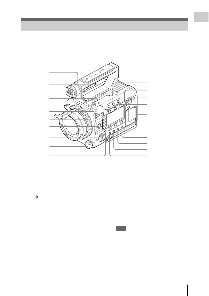
Location and Function of Parts
For functions and usage, see the pages in parentheses.
The following illustrations are with the battery adaptor (page 14) removed.
For removing the battery adaptor, see “Removing a battery pack” (page 19).
Overview
1
2
3
4
5
6
7
8
9
10
1. Handle
2. LOCK switch
Disables operations on the side operating panel.
3. Viewfinder shoe
4. Tape measure hook/Image sensor position
index
The mark and tape measure hook are on a
plane with the image sensor. To measure the
precise distance between the camcorder and the
subject, use this mark or tape measure hook as a
reference.
You can attach the end of a tape measure to the
hook, and measure the distance from the subject.
5. Flange focal length adjustment screw
(page 22)
6. Lens mount (page 21)
7. REC (recording start/stop) button/lamp
(page 30)
8. SEL/SET (select/set) dial (MENU dial)
(pages 38, 40)
Selects the item in the menu or changes the
setting value.
11
12
13
14
Sub display/Control
buttons block (page 12)
SxS memory card slot
block (page 12)
Right side connector
panel (page 12)
15
16
17
18
9. ND FILTER select switch
ND filters are available for keeping the
aperture in a proper range.
Clear: ND filter not used
1
/8ND
0.9:
1
1.8:
/64ND
10. CANCEL/BACK button (pages 38, 40)
11. Accessory mounting screw holes
Type of screw: 1/4-20UNC (× 4)
Type of screw: 3/8-16UNC (× 5)
Length of engagement: 9 mm
3
(
/8 inch) or less
Note
Do not apply excessive force to the mounted
accessory. It may damage the screw thread.
12. ASSIGN (assignable) 1/2/3 buttons (page
33)
13. Built-in speaker (page 30)
Location and Function of Parts
9

14. Power switch
Overview
Set to the ON position (=) to turn the power on.
Set to the OFF position (1) to turn the power
off.
Notes
• This camcorder uses a small amount of standby
power even when the power switch is set to OFF.
Remove the battery pack if the camcorder will not
be used for a prolonged period.
• When removing the battery pack or the DC IN
power, be sure to first set the power switch to the
OFF position. Removing the battery pack or the
DC IN power while the camcorder is ON may
cause damage to the camcorder or the memory
card.
15. BRIGHTNESS button
Adjusts brightness of the sub display in 4 steps.
16. STATUS (status display on/off) button
Displays status screens on the LCD monitor/
viewfinder/external video monitor.
Turn the MENU dial (page 9) to switch the
screens in sequence.
Camera status screen
Displays the electronic shutter settings or the
status of the lens.
Gain Amount of gain up (dB) or
Shutter Electronic shutter settings
Gamma Gamma category and curve
Zebra1 On/off and setting level of
Zebra2 On/off and setting level of
White White balance mode and
Iris T value of iris
Focal Length Focal length (mm/inch)
Focus Distance Focus distance (m/feet)
Depth Of Field Depth of field (m/feet)
Audio status screen
Displays the input settings for each channel,
audio level meter, and wind filter setting.
Level Level meter
Source Input source
Reference Reference level setting
System status screen
Displays the video signal settings.
System
Frequency
Picture Size Picture size that is recorded on
sensitivity (ISO)
Zebra1
Zebra2
setting
System frequency
an SxS memory card
Rec Format
(Main)
Gamma Gamma category that is
Rec Function Special recording that is set to
MPEG2 Proxy On/off setting of MPEG2
Recording format that is
recorded on the SxS memory
card
recorded on the SxS memory
card
on, and its setting
proxy (PMW-F55 only)
Video output status screen
Displays the video output settings of SDI 1 to
SDI 4, HDMI, and test video output.
Picture size Output picture size
C.Space Output form
Freq Output rate
Gamma Gamma
Assignable button status screen
Displays the function that is assigned to each
ASSIGN button.
1 to 4 Functions that are assigned to
the Assign 1 to 4 buttons
Battery status screen
Displays information of the battery or DC IN
power.
Detected Battery Battery type
Remaining Remaining charge level (%)
Charge Count Number of times that the
Capacity Remaining capacity (Ah)
Voltage Voltage (V)
Manufacture
Date
Power Source Power source
Supplied Voltage Supplied voltage
battery is charged
Manufacture date of the
battery
Media status screen
Displays the remaining space, available
recording time, and estimated service life of the
recording media (SxS memory card A/SxS
memory card B/SD card/AXS memory).
Protect
information
Remaining
Remaining space and
available recording time
Life
Estimated service life
17. OPTION button (page 35)
18. MENU (menu display on/off) button (page
40)
Location and Function of Parts
10
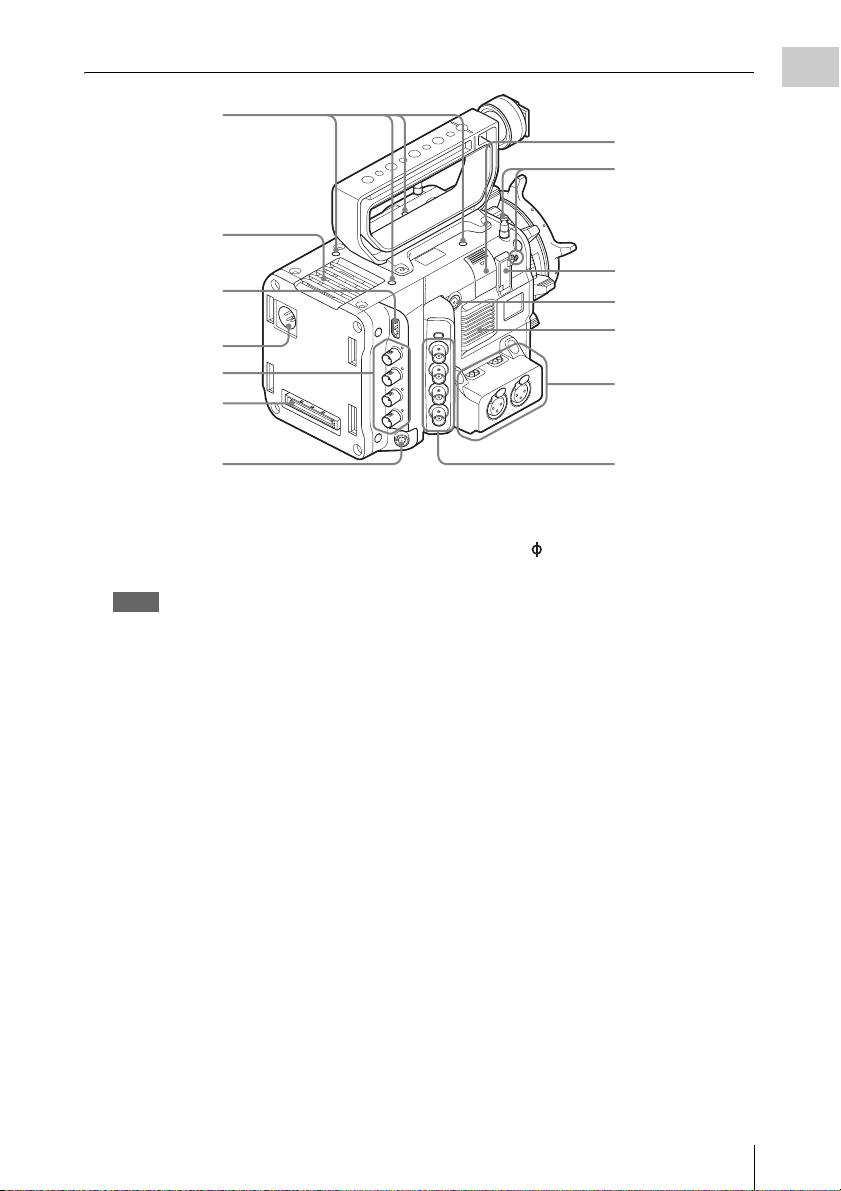
Air outlet
Overview
1
7
8
9
2
10
Air inlet
3
4
5
Audio connector
panel (page 12)
6
1. Accessory mounting screw holes
Type of screw: 1/4-20UNC (× 4)
Length of engagement: 9 mm
3
/8 inch) or less
(
Notes
• Do not apply excessive force to the mounted
accessory. It may damage the screw thread.
• When attaching an accessory, do not cover the air
inlet or air outlet.
2. HDMI OUT connector (page 60)
3. DC IN connector (page 20)
4. SDI OUT 1 to 4 (serial digital output)
connectors (BNC type) (page 60)
5. Mounting terminal for an expansion unit
(pages 19, 28)
6. REMOTE (remote control) connector (8-
pin)
Connect an external device such as a remote
control unit.
7. USB wireless LAN module retracting part
(To be supported by future upgrade.)
Left side connector
panel (page 13)
8. Tape measure hook/Image sensor position
index
The mark and tape measure hook are on a
plane with the image sensor. To measure the
precise distance between the camcorder and the
subject, use this mark or tape measure hook as a
reference.
You can attach the end of a tape measure to the
hook, and measure the distance from the subject.
9. VF (viewfinder output) connector (page
22)
10. ASSIGN 4 (assignable 4) button (page 33)
Location and Function of Parts
11
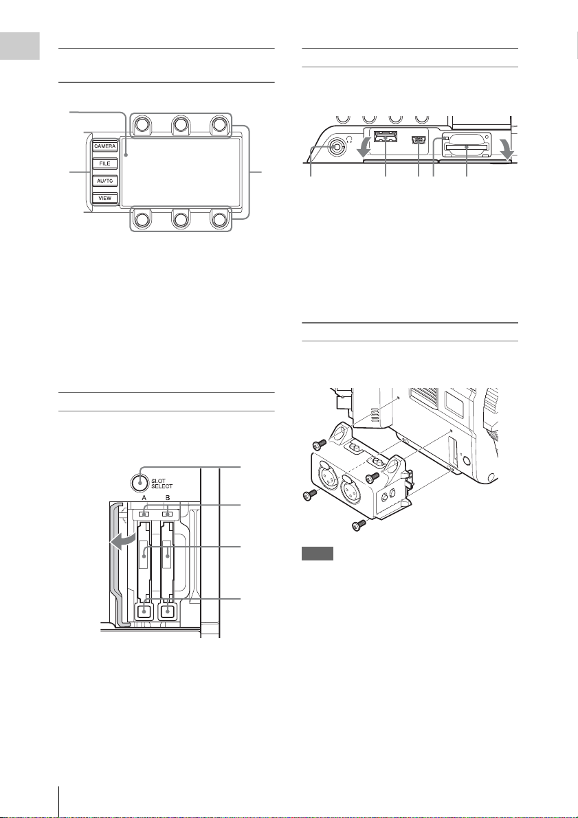
Sub display/Control buttons block (page
Overview
38)
1
Right side connector panel
The USB connector and SD card slot are located
behind the cover.
23
Open the
cover.
2
4 531
1. Headphones connector (stereo mini jack)
(page 30)
1. Sub display
2. Function buttons
• CAMERA button
• FILE button (To be supported by future
upgrade.)
• AU/TC (audio/time code) button (To be
supported by future upgrade.)
• VIEW button
3. Item button
2. USB connector (A)
3. USB connector (Mini B)
4. ACCESS (SD card access) lamp (page 27)
5. SD card slot (page 27)
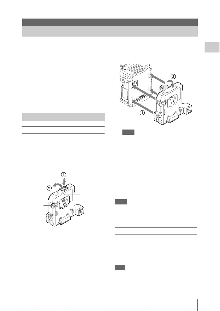
Audio connector panel
Attach the supplied audio connector panel as
follows.
SxS memory card slot block (page 24)
The SxS memory card slots are located behind the
cover.
1
2
Open the
cover.
1. SLOT SELECT (SxS memory card select)
button
2. ACCESS (SxS memory card access) lamps
3. SxS memory card slots
4. EJECT (SxS memory card eject) buttons
3
4
Notes
• Attach/remove the audio connector panel while the
camcorder is turned off.
• When attaching the audio connector panel, make sure
not to catch the cap.
• When removing the audio connector panel, pull it
away slowly from the body of the camcorder, as shown
in the diagram above.
• Applying excessive force to remove the audio
connector panel may damage it.
Open the
cover.
Location and Function of Parts
12
1
2
1. AUDIO IN CH1/AUDIO IN CH2
(external audio input selection) switches
Switch input signal (external microphone,
external audio device, etc.).
supported by future upgrade
(AES/EBU is
.)
2. AUDIO IN (CH-1, CH-1/2) /AUDIO IN
(CH-2, CH-3/4) connectors
Input external microphone or audio
equipment signals.
3. CH1 MIC +48V/OFF, CH2 MIC +48V/
OFF (external microphone input
selection) switches
Supply phantom power (48 V) to the external
microphone when you set this switch to
“MIC +48V.”
Left side connector panel
1
2
Bottom
Overview
3
1
1. Accessory mounting screw holes
Type of screw: 1/4-20UNC (× 3)
Type of screw: 3/8-16UNC (× 3)
Length of engagement: 9 mm
3
/8 inch) or less
(
Note
Do not apply excessive force to the mounted
accessory. It may damage the screw thread.
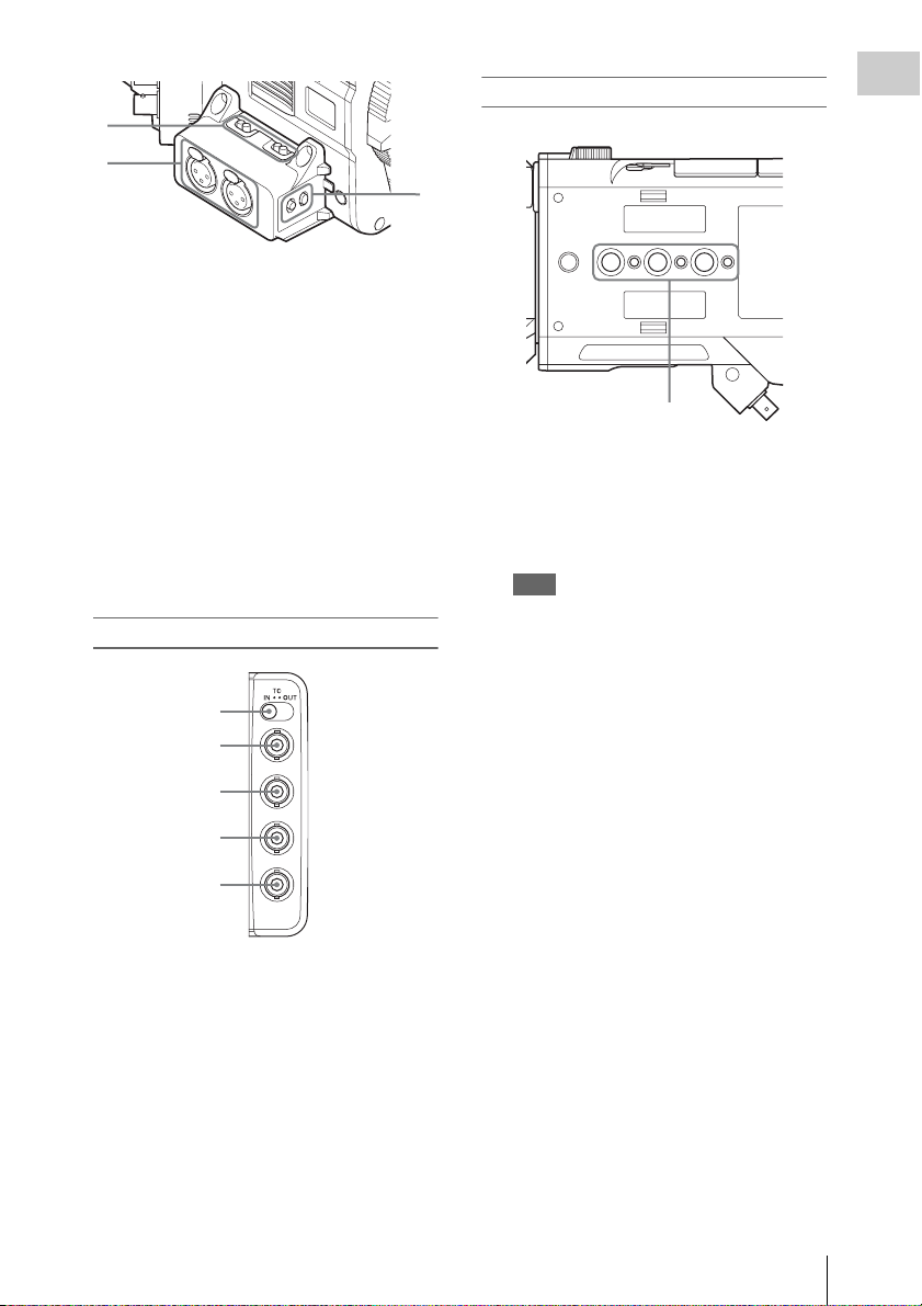
3
4
5
1. TC IN/OUT (timecode input/output
selection) switch (page 62)
2. TC (timecode input/output) connector
(BNC type) (page 62)
3. GENLOCK IN connector (BNC type)
(page 62)
4. TEST OUT (analog video output)
connector (BNC type) (page 60)
5. SHUTTER connector (BNC type)
To be supported by future upgrade
.
Location and Function of Parts
13
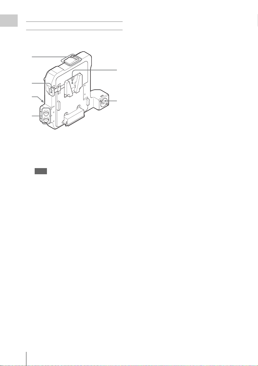
Battery adaptor
Overview
For attaching/removing the battery adaptor, see
“Using a Battery Pack” (page 19).
1
2
5
3
4
1. Release button/ejection lever
2. Battery release lever
3. Expansion IF connector
4. DC OUT 1/2 connector
Note
When connecting a device, use one with current
consumption of 1.8 A or less.
5. Battery pack attaching part
6. DC IN connector (page 20)
6
Location and Function of Parts
14
On-Screen Indications
Sub Display Screen
When turning on the camcorder, the sub display appears and you can check the status of the camcorder
and set the basic items.
The screen is switched by pressing the function button on the left of the sub display (page 12).
Item name/
Setting value/
Function display
screen
Status screen
Overview
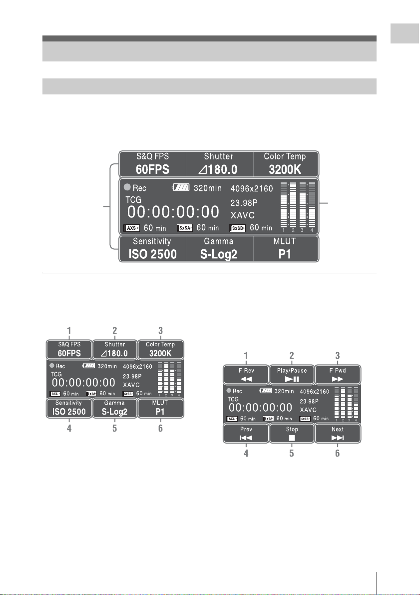
Item name/Setting value/Function display
screen
CAMERA setting (page 39)
1. S&Q FPS
Displays and sets Slow & Quick Motion/
Frame Rate.
2. Shutter
Displays and sets shutter speed/angle.
3. Color Temp
Displays and sets color temperature.
4. Sensitivity/Gain/Exposure Index
Displays and sets sensitivity/gain (ISO/dB/
EI).
5. Gamma
Displays and sets gamma category.
6. MLUT
Displays and sets monitor LUT.
VIEW-1
1. F Rev m
Fast reverse
2. Play/Pause BX
Play/pause
3. F Fwd M
Fast forward
4. Prev .
Previous clip jump
On-Screen Indications
15
Overview
5. Stop x
Stop
6. Next >
Clip directional jump
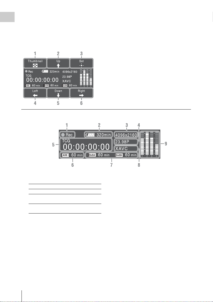
VIEW-2
Status screen
1. Thumbnail
Displays or cancels the display of the
thumbnail screen.
2. Up
Moves the cursor up.
3. Set
Confirms the selected item.
4. Left
Moves the cursor to the left.
5. Down
Moves the cursor down.
6. Right
Moves the cursor to the right.
1. Special recording/operation status
indication
zRec Recording in progress
Stby Standby for recording
zS&Q Rec Slow & Quick Motion
S&Q Stby Standby for Slow & Quick
recording in progress
Motion recording
2. Battery remaining charge/DC IN voltage
indication (page 20)
3. Recording format (picture size) indication
(page 31)
Displays the picture size that is recorded on
an SxS memory card.
4. System frequency and scan method
indication (page 31)
5. Time data indication (page 32)
6. AXS memory status/remaining space
indication (page 29)
On-Screen Indications
16
7. A/B slot media status/remaining space
indication (page 25)
8. Recording format (codec) indication (page
31)
Displays the format that is recorded on an
SxS memory card.
9. Audio level meter (4CH)
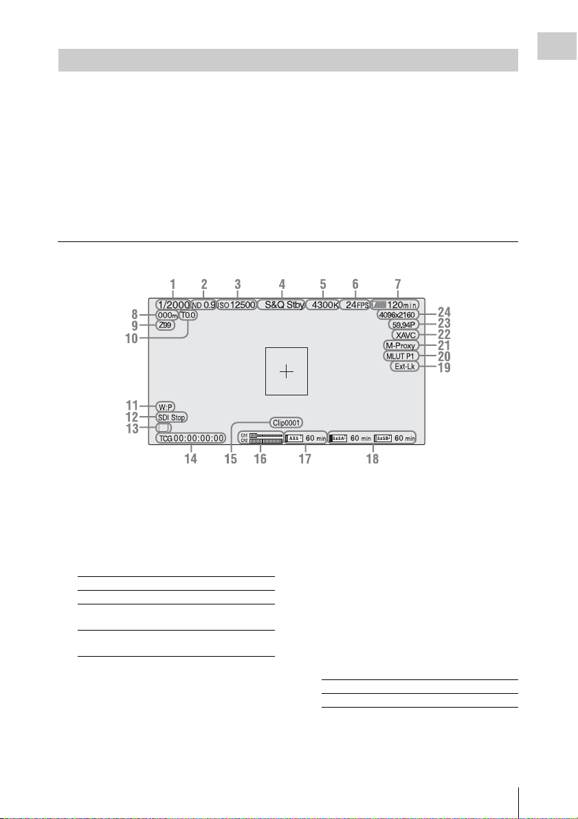
LCD Monitor/Viewfinder Screen
While recording, standing by to record, or playback, the statuses and settings of this unit are superimposed
on the LCD monitor/viewfinder screen.
The statuses and settings of this unit can be turned on/off using the setup menu or by the assignable button.
The statuses and settings of this unit can be independently turned on/off (page 53).
To turn on/off on the setup menu
Turn on/off the statuses and settings of this unit on “Setting” in “Display On/Off” (page 53) of the VF
menu.
To turn on/off by the assignable button
Assign “Display” to one of the assignable buttons (page 33). You can turn on/off the statuses and settings
of this unit by pressing the assignable button.
Information displayed on the screen while recording
SD
Overview
1. Shutter mode/shutter speed indication
(page 44)
2. ND filter indication (page 9)
3. Gain indication (page 43)
4. Special recording/operation status
indication
zRec Recording in progress
Stby Standby for recording
zS&Q Rec Slow & Quick Motion
S&Q Stby Standby for Slow & Quick
recording in progress
Motion recording
5. Color temperature indications (page 41)
6.
S&Q motion frame rate indication
(page 44)
7. Battery remaining charge/DC IN voltage
indication (page 20)
8. Focus position indication
Displays focus position (only when a lens that is
compatible with the focus setting display
function is attached).
9. Zoom position indication
Displays zoom position in the range of 0 (wide
position) to 99 (tele position) (only when a lens
that is compatible with the zoom setting display
function is attached).
10. Iris position indication
Displays iris position (only when a lens that is
compatible with the iris setting display function
is attached).
11. White balance mode indication (page 41)
W:P Preset mode
W:M Memory mode
12. Control status of SDI output indication
(page 50)
13. SD card indication
On-Screen Indications
17

14. Time data indication (page 32)
Overview
15. Clip name indication (page 31)
16. Audio level meter
17. AXS memory status/remaining space
indication (page 29)
When the left side of the icon is orange,
recording is possible.
When the green lamp on the upper right of the
icon lights, playback is possible.
18. A/B slot media status/remaining space
indication (page 25)
When the left side of the icon is orange,
recording is possible.
When the green lamp on the upper right of the
icon lights, playback is possible.
19. Timecode external lock indication
When the unit is locked to the timecode of an
external device, “Ext-Lk” appears.
20. Gamma/Monitor LUT indication (pages
45, 50)
Displays the gamma setting value. When
“Shooting Mode” (page 57) is set to “Cine EI,”
the Monitor LUT setting appears instead of the
gamma setting.
21. Simultaneous recording status indication
(page 33)
M-Proxy: Displayed when the function of
simultaneous recording on one memory card is
effective.
22. Recording format (codec) indication (page
31)
Displays the format that is recorded on an
SxS memory card.
23. System frequency and scan method
indication (page 31)
24. Recording format (picture size) indication
(page 31)
Displays the picture size that is recorded on
an SxS memory card.
Information displayed on the playback screen
The following information is superimposed on
the playback picture.
1. Clip no./total number of clips
2. Playback mode
3. Playback format (picture size)
4. Battery charge remaining/DC IN voltage
5. Playback format (frame rate)
6. Time data
You can switch between timecode and duration
by using “TC Display” (page 54) in the TC/UB
menu.
7. Audio levels
The audio levels for the recording are displayed.
8. Clip name
9. Media
A mark appears to the left if the memory
card is write-protected.
10. Playback format (codec)
On-Screen Indications
18
Preparations
Power Supply
You can use a battery pack or AC power via an
AC adaptor.
For safety, use only the Sony battery packs and
AC adaptors listed below:
Lithium-ion Battery Pack
BP-FL75
BP-L80S
AC Adaptor
AC-DN2B
AC-DN10
Using a Battery Pack
Attaching a battery pack
1 Attach the battery adaptor (supplied) to
the camcorder.
Press the release button (1) of the battery
adaptor to pop up the ejection lever, then raise
the ejection lever (2).
Battery pack
Battery
release
lever
attaching part
Insert the projection of the battery adaptor into
the slot on the rear of the camcorder (1), then
lower the ejection lever (2).
Notes
• Before attaching the battery adaptor, make sure
that the ejection lever is raised.
• Before lowering the ejection lever, make sure that
the four hooks are attached securely. If the four
hooks are not attached securely, it may cause the
connection to be poor or damage the camcorder
and battery adaptor.
2 Attach a battery pack to the battery
adaptor.
Insert the battery pack into the battery pack
attaching part of the battery adaptor, then slide
the battery pack down to lock it in place.
Notes
• Before use, charge the battery pack with the battery
charger.
• A warm battery pack immediately after use may not be
able to be fully recharged.
Preparations
Removing a battery pack
Unlock the battery pack by sliding it up while
pressing the battery release lever, then remove it.
Press the release button and raise the ejection
lever, then remove the battery adaptor by pulling
it out while sliding upward.
Note
Remove the battery adaptor while supporting the
camcorder by hand.
Power Supply
19
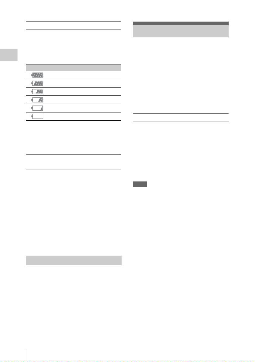
Checking remaining battery charge
When recording or playback is in progress on the
battery pack, an icon to show the current battery
remaining time and battery voltage are displayed
on the sub display screen (page 15) and LCD
monitor/viewfinder screen (page 17).
Preparations
Icon Remaining charge
100% to 91%
90% to 71%
70% to 51%
50% to 31%
30% to 11%
10% to 0%
The camcorder indicates the remaining usage
time in minutes by calculating the available time
with the battery pack if operation is continued at
the current rate of power consumption.
If the remaining battery charge becomes
low
If the remaining battery charge decreases to a
certain level during operation, a low-battery
message, flashing of the REC lamp, and a beep
sound will warn you.
If the remaining charge further decreases to a
level at which operation cannot be continued, a
battery-empty message appears.
Replace the battery pack with one that is fully
charged.
To change the message levels
These settings can be changed with “Battery
Alarm” (page 58) in the System menu.
Setting the Clock
When you turn the camcorder on for the first time
after purchasing or replacing the backup battery,
the Initial Setting display appears on the
viewfinder screen.
Set the date and time of the built-in clock, using
this display.
Time Zone
The value shows the time difference from UTC
(Coordinated Universal Time).
Change the setting if needed.
Setting the time and date
Turn the MENU dial (page 9) to move the cursor,
then press the MENU dial to set each menu item.
When you press the MENU dial when the cursor
is on “Finish,” the setting display disappears, the
clock setting is completed.
After the setting display disappears, “Clock Set”
(page 58) in the System menu can be used to set
“Time Zone” and date/time.
Notes
• If the clock setting is cleared because the backup
battery fully discharged when no power was supplied
(no battery pack and no DC IN connection), the Initial
Setting display will be displayed when you next turn
the camcorder on.
• While the Initial Setting display is shown, no other
operation, except turning the power off, is permitted
until you finish the setting for this display.
Using AC Power (DC IN Power)
The camcorder works with AC power by using
the AC adaptor AC-DN2B/AC-DN10 (optional)
and DC cable CCDD-X2 (optional).
Setting the Clock
20

Attaching Optional Devices
Attaching a PL mount lens
1 Remove the mount cover from the lens
mount by turning the lens mount frame
counterclockwise.
Attaching a Lens
Recommended lenses
SCL-P35T20 (Focal length: 35 mm)
SCL-P50T20 (Focal length: 50 mm)
SCL-P85T20 (Focal length: 85 mm)
SCL-PK6 (set of 6 lenses)
• SCL-P20T20 (Focal length: 20 mm)
• SCL-P25T20 (Focal length: 25 mm)
• SCL-P35T20A (Focal length: 35 mm)
• SCL-P50T20A (Focal length: 50 mm)
• SCL-P85T20A (Focal length: 85 mm)
• SCL-P135T20 (Focal length: 135 mm)
SCL-P11X15
For details about available lenses for the camcorder,
contact a Sony service representative.
Caution
Do not leave the lens facing the sun. Direct
sunlight can enter through the lens, be focused in
the camcorder, and cause fire.
Notes
• Attach/remove a lens while the camcorder is turned
off.
• A lens is a precision part. Do not place the lens directly
with the mount part down. Attach the cover supplied
with the lens.
• The lens interface of the camcorder is set to “Type C,”
to correspond with the lenses SCL-P35T20/P50T20/
P85T20, SCL-P11X15 and lenses with a Cooke-type
connector. When using a lens with an ARRI-type
connector, set “Lens interface” (page 45) in the
Camera menu to “Type A.” Set to “Off” for SCL-PK6
or other lenses. If this setting is not correct, an alert
message appears when the camcorder is turned on after
attaching the lens.
2 Insert the lens into the lens mount by
matching the concave part of the lens to
the locating pin o n the upper right of the
lens mount.
3 Fix the lens by turning the lens mount
frame clockwise while holding the lens.
2
3
Preparations
Attaching Optional Devices
21

To attach an ARRI* LDS lens or Cooke/i lens
Match the contact of the lens to the hot shoe of the
camcorder.
Hot shoe for the Cooke/i lens
Preparations
Removing a lens
Remove a lens with the following steps.
1 Turn the lens mount frame
counterclockwise while holding the lens
from underneath.
2 Pull the lens forward.
Note
If another lens will not be attached soon, attach the
mount cover and fix the lens mount frame by turning it
clockwise.
Hot shoe for the ARRI LDS lens
* ARRI Group
Adjusting a flange focal length
You need to adjust the flange focal length
(distance from the mounting flange to the film
plane) for the following cases.
• When a lens is attached for the first time.
• When a lens is changed.
• When focus is not achieved for either tele or
wide angle while using a zoom lens.
You can adjust the flange focal length by turning
the screw for the flange focal length (page 9).
Use a hex key (7/64) for adjusting.
When turning the screw to the left, the flange
focal length becomes long. When turning the
screw to the right, the flange focal length
becomes short. Turn the screw slowly.
Notes
• The camcorder will not work if the screw for the flange
focal length is turned too much. Stop tur ning the screw
when the amount of the flange focal length no longer
changes.
• Use a hex key of the specified size. Otherwise, the
screw head may be damaged and you may be unable to
turn the screw.
Selecting the lens file
By storing the adjustment value of the attached
lens as a file, you can easily perform adjustment
for the lens by loading the file.
Load the file in “Lens File” (page 55) of the File
menu.
Attaching a Viewfinder
Available viewfinders for the camcorder
• DVF-L350: LCD color viewfinder
• DVF-L700: LCD color viewfinder
• DVF-EL100: OELD color viewfinder
Caution
Do not leave the camcorder with the eyepiece of
the viewfinder facing the sun. Direct sunlight can
enter through the eyepiece, be focused in the
viewfinder, and cause fire.
Note
Attach/remove the viewfinder while the camcorder is
turned off.
For details about attaching the viewfinder, refer to
the operating instructions of the viewfinder.
Attaching Optional Devices
22
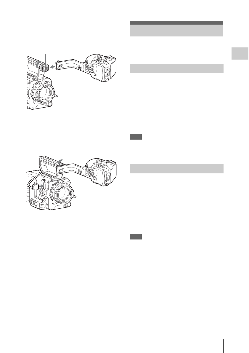
1 Loosen the fixing ring of the viewfinder
shoe, align the slot of the viewfinder,
then attach the viewfinder by sliding it
horizontally.
Viewfinder shoe
2 Tighten the fixing ring after
determining the left and right position
of the viewfinder, then connect the
viewfinder cable to the VF connector of
the camcorder.
To remove the viewfinder
Loosen the fixing ring for the viewfinder, raise
the stopper, then remove the viewfinder by
sliding it in the reverse direction for when
attaching.
Setting the Basic Action
Before recording, make the basic settings, as
required.
Preparations
Shooting Mode
You can switch between the “Cine EI” mode
(allows you to use the camcorder as a film
camera, where the movie is edited postproduction, rather than at the time of shooting),
and the “Custom” mode (allows you to edit
pictures as you make the movie, by accessing all
the setting items).
Switch the mode by using “Shooting Mode” in
“Base Setting” (page 57) of the System menu.
Note
The shooting mode can be selected if the AXS-R5 is
attached. If the AXS-R5 is not attached, “Shooting
Mode” is locked to “Custom.”
Main Recorded Signal
Set the predominant signal format to be used.
Set the format by using “Main Operation” in
“Base Setting” (page 57) of the System menu.
The RAW signal is recorded on the AXR-R5
attached to the camcorder, the YPbPr signal is
recorded on the SxS memory card in the
camcorder. Since the RGB signal is output from
the SDI 1/2 connector of the camcorder, record it
on an external device such as SR-R1.
Note
The RAW signal can be selected only when attaching the
AXS-R5. If the AXS-R5 is not attached, “Main
Operation” is locked to “YPbPr” or “RGB.”
Setting the Basic Action
23

Color Space
Select the color reproducibility.
Select it by u sing “Color Space” in “Ba se Setting”
(page 57) of the System menu.
S-Gamut: Allows you to record in a wider gamut
Preparations
that is comparable with a film camera. You
can expand the color expression in the postproduction process.
Note
“White Switch” (page 41) of the Camera menu can
be selected from among Preset 3200K/Preset
4300K/Preset 5500K. “Gamma” (page 45) of the
Paint menu is locked to “S-Log2.”
Normal: Reproduces color as would be
reproduced using a traditional camera, by the
Matrix setting.
Using SxS Memory Cards
This camcorder records audio and video on SxS
memory cards (optional) inserted in the card slots.
About SxS Memory Cards
Use the following Sony SxS memory cards.
Available memory cards differ depending on the
recording format.
SxS PRO+
SBP-128B, SBP-64B: Available for all recording
formats.
SxS PRO
SBP-64A, SBP-32: XAVC 1920 × 1080P, MPEG
1920 × 1080P/i
SxS-1
SBS-64G1A, SBS-32G1A: MPEG 1920 ×
1080P/i
Operations are not guaranteed with other memory
cards.
These memory cards comply with the
ExpressCard standard.
For details on using SxS memory cards and usagerelated precautions, refer to the instruction manual
for the SxS memory card.
Using SxS Memory Cards
24
SxS, SxS PRO, and SxS-1 are tra demarks of Sony
Corporation.
The ExpressCard word mark and logo are owned
by Personal Computer Memory Card
International Association (PCMCIA) and are
licensed to Sony Corporation. All other
trademarks are the property of their respective
owners.
Inserting an SxS Memory Card
1 Open the cover of the card slot block
(page 12).
Loading...