


REVISION HISTORY |
AZ1-A CHASSIS |
|
MODEL |
PART NO.: 9-888-122- |
|
KLV-22BX300
KLV-26BX300
KLV-32BX300
KLV-40BX400
NO. |
SUFFIX |
DATE |
SUPP / CORR |
DESCRIPTION |
|
|
|
|
|
1 |
-01 |
2009/12 |
_ _ |
1st Issue |
|
|
|
|
|
|
|
|
|
|
|
|
|
|
|
|
|
|
|
|
|
|
|
|
|
|
|
|
|
|
|
|
|
|
|
|
|
|
|
|
|
|
|
|
|
|
|
|
|
|
|
|
|
|
|
|
|
|
|
|
|
|
|
|
|
|
|
|
|
|
|
|
|
|
|
|
|
|
|
|
SERVICE MANUAL
AZ1-A CHASSIS
|
MODEL |
COMMANDER |
DEST. |
MODEL |
COMMANDER DEST. |
|||||||||||||||||||||||||||||||||||
|
|
|
|
|
|
|
|
|
|
|
|
|
|
|
|
|
|
|
|
|
|
|
|
|
|
|
|
|
|
|
|
|
|
|
|
|
|
|
|
|
|
KLV-22BX300 |
RM-GA019 |
ARM, Iran, India, |
KLV-32BX300 |
RM-GA019 |
ARM, Iran, India, |
||||||||||||||||||||||||||||||||||
|
|
|
|
|
|
|
|
|
|
|
|
|
|
|
|
Indonesia, Malaysia, |
|
|
|
|
|
|
|
|
|
|
|
|
|
|
|
|
Indonesia, Malaysia, |
|||||||
|
|
|
|
|
|
|
|
|
|
|
|
|
|
|
|
New Zealand, |
|
|
|
|
|
|
|
|
|
|
|
|
|
|
|
|
Nigeria, Saudi Arabia, |
|||||||
|
|
|
|
|
|
|
|
|
|
|
|
|
|
|
|
Nigeria, Saudi Arabia, |
|
|
|
|
|
|
|
|
|
|
|
|
|
|
|
|
Singapore, SOGUL, |
|||||||
|
|
|
|
|
|
|
|
|
|
|
|
|
|
|
|
Ukraine, Singapore, |
|
|
|
|
|
|
|
|
|
|
|
|
|
|
|
|
Ukraine, South Africa, |
|||||||
|
|
|
|
|
|
|
|
|
|
|
|
|
|
|
|
SOGUL, South Africa, |
|
|
|
|
|
|
|
|
|
|
|
|
|
|
|
|
Thailand, Tunisia, |
|||||||
|
|
|
|
|
|
|
|
|
|
|
|
|
|
|
|
Thailand, Tunisia, |
KLV-40BX400 |
|
|
|
|
|
|
|
|
|
|
|
Phillipines |
|||||||||||
|
KLV-26BX300 |
|
|
|
|
|
|
|
|
|
|
|
Phillipines |
RM-GA019 |
ARM, Iran, Indonesia, |
|||||||||||||||||||||||||
|
RM-GA019 |
ARM, Iran, India, |
||||||||||||||||||||||||||||||||||||||
|
|
|
|
|
|
|
|
|
|
|
|
|
|
|
|
|
Malaysia, Nigeria, |
|||||||||||||||||||||||
|
|
|
|
|
|
|
|
|
|
|
|
|
|
|
|
Indonesia, Malaysia, |
|
|
|
|
|
|
|
|
|
|
|
|
|
|
|
|
Saudi Arabia, |
|||||||
|
|
|
|
|
|
|
|
|
|
|
|
|
|
|
|
New Zealand, |
|
|
|
|
|
|
|
|
|
|
|
|
|
|
|
|
Singapore, Ukraine, |
|||||||
|
|
|
|
|
|
|
|
|
|
|
|
|
|
|
|
Nigeria, Saudi Arabia, |
|
|
|
|
|
|
|
|
|
|
|
|
|
|
|
|
Vietnam, Phillipines |
|||||||
|
|
|
|
|
|
|
|
|
|
|
|
|
|
|
|
Singapore, SOGUL, |
|
|
|
|
|
|
|
|
|
|
|
|
|
|
|
|
Tunisia, South Africa |
|||||||
|
|
|
|
|
|
|
|
|
|
|
|
|
|
|
|
South Africa, Ukraine, |
|
|
|
|
|
|
|
|
|
|
|
|
|
|
|
|
India,Thailand |
|||||||
|
|
|
|
|
|
|
|
|
|
|
|
|
|
|
|
Thailand, Tunisia, |
|
|
|
|
|
|
|
|
|
|
|
|
|
|
|
|
|
|
|
|
||||
|
|
|
|
|
|
|
|
|
|
|
|
|
|
|
|
Phillipines |
|
|
|
|
|
|
|
|
|
|
|
|
|
|
|
|
|
|
|
|
||||
|
|
|
|
|
|
|
|
|
|
|
|
|
|
|
|
|
|
|
|
|
|
|
|
|
|
|
|
|
|
|
|
|
|
|
|
|
|
|
|
|
|
|
|
|
|
|
|
|
|
|
|
|
|
|
|
|
|
|
|
|
|
|
|
|
|
|
|
|
|
|
|
|
|
|
|
|
|
|
|
|
|
KLV-22BX300 |
KLV-26BX300 |
RM-GA019
KLV-32BX300
KLV-40BX400
LCD COLOR TV
KLV-22, 26, 32 BX300, 40 BX400
RM-GA019
TABLE OF CONTENTS
Section Title |
Page |
Section Title |
Page |
||||||
|
|
|
|
|
|
|
|
|
|
1. |
SAFETY NOTES |
|
|
5. |
DIAGRAMS |
|
|
||
|
1-1. Caution Handling of LCD Panel ..................................... |
3 |
|
5-1. Block Diagram ............................................................... |
11 |
||||
|
1-2. Safety Check Out ............................................................. |
3 |
|
5-1-1. KLV-22, 26, 32 BX300 ..................................... |
11 |
||||
|
1-3. Leakage Test .................................................................... |
3 |
|
5-1-2. KLV-40BX400 ..................................... ............ |
12 |
||||
|
1-4. WARNING ! .................................................................... |
3 |
|
5-2. Wire Dressing and Connector Diagram ....................... |
13 |
||||
|
1-5. Lead Free Information ..................................................... |
4 |
|
5-2-1. KLV-22BX300 ................................................... |
13 |
||||
|
1-6. Attachment & Detachment of MDF61 Connector ......... |
4 |
|
5-2-2. KLV-26BX300 ................................................... |
14 |
||||
|
1-7. Attachment, Detachment & Confirmation of Lock |
|
|
|
5-2-3. KLV-32BX300 ................................................... |
15 |
|||
|
Condition of JST IBH Connector.................................... |
4 |
|
5-2-4. KLV-40BX400 ................................................... |
16 |
||||
|
|
|
|
|
|
5-3. Circuit Board Location .................................................. |
17 |
||
|
|
|
|
|
|
5-3-1. KLV-22BX300 ................................................... |
17 |
||
2. |
SELF DIAGNOSTIC FUNCTION |
|
|
|
5-3-2. KLV-26BX300 ................................................... |
17 |
|||
|
2-1. Overview of Control Buttons .......................................... |
5 |
|
5-3-3. KLV-32BX300 ................................................... |
17 |
||||
|
2-2. LED Display Specification.............................................. |
5 |
|
5-3-4. KLV-40BX400 ................................................... |
17 |
||||
|
2-3. LED Display Control ....................................................... |
5 |
|
|
|
|
|
||
|
2-4. LED Pattern ..................................................................... |
5 |
|
|
|
|
|
||
|
2-5. Standby LED Error Display and Board |
|
|
6. |
DISASSEMBLY, EXPLODED VIEWS AND |
|
|
||
|
Replacement Order .......................................................... |
6 |
|
OTHER PARTS |
|
|
|||
|
2-6. Triage Chart ..................................................................... |
7 |
|
6-1. Disassembly & Exploded Views ................................... |
18 |
||||
|
|
|
|
|
|
6-1-1. KLV-22BX300 .................................................... |
18 |
||
|
|
|
|
|
|
6-1-2. KLV-26BX300 .................................................... |
19 |
||
3. |
TROUBLE SHOOTING |
|
|
|
6-1-3. KLV-32BX300 .................................................... |
20 |
|||
|
3-1. Flowchart ......................................................................... |
8 |
|
6-1-4. KLV-40BX400 .................................................... |
21 |
||||
|
3-1-1. No Power ....................................................................... |
8 |
|
6-2. Other Parts ..................................................................... |
22 |
||||
|
3-1-2. Video Problem ............................................................... |
9 |
|
6-2-1. KLV-22BX300 .................................................... |
22 |
||||
|
3-1-3. Audio Problem .............................................................. |
9 |
|
6-2-2. KLV-26BX300 .................................................... |
22 |
||||
|
|
|
|
|
|
6-2-3. KLV-32BX300 .................................................... |
23 |
||
|
|
|
|
|
|
6-2-4. KLV-40BX400 .................................................... |
24 |
||
4. |
SERVICE ADJUSTMENTS |
|
|
|
|
|
|
|
|
|
4-1. Accessing Self Diagnostic Menu .................................. |
10 |
|
|
|
|
|
||
|
4-2. Accessing Service Mode ............................................... |
10 |
|
OPERATING INSTRUCTIONS |
|
|
|||
|
4-3. GAISOU Adjustment .................................................... |
10 |
|
|
|
|
|
||
– 2 –
KLV-22, 26, 32 BX300, 40 BX400
RM-GA019
SECTION 1
SAFETY NOTES
1-1. Caution Handling of LCD Panel
When installing the LCD Panel, make sure you are grounded with a wrist band.
When installing the LCD Panel on the wall, the panel must be secured using the 4 mounting holes on the rear cover.
1)Do not press the panel or frame edge to avoid the risk of electric shock.
2)Do not scratch or press on the panel with any sharp objects.
3)Do not leave the module in high temperature or in areas of high humidity for an extended period of time.
4)Do not expose the LCD panel to direct sunlight.
5)Avoid contact with water. It may cause short circuit within the module.
6)Disconnect the AC adapter when replacing the backlight (CCFL) or inverter circuit. (High voltage occurs at the inverter circuit at 650Vrms)
7)Always clean the LCD panel with a soft cloth material.
8)Use care when handling the wires or connectors of the inverter circuit. Damaging the wires may cause a short circuit.
9)Protect the panel from ESD to avoid damaging the electronic circuit (C-MOS).
1-2. Safety Check-Out
After correcting the original service problem, perform the following safety checks before releasing the set to the customer:-
1)Check the area of your repair for unsoldered or poorly soldered connections. Check the entire board surface for solder splashes and bridges.
2)Check the interboard wiring to ensure that no wires are "pinched" or contact high-wattage resistors.
3)Check all control knobs, shields, covers, ground straps and mounting hardware have been replaced. Be absolutely certain you have replaced all the insulators.
4)Look for unauthorized replacement parts, particularly transistors that were installed during a previous repair. Point them out to the customer and recommend their replacement.
5)Look for parts which, though functioning show obvious signs of deterioration. Point them out to the customer and recommend their replacement.
6)Check the line cords for cracks and abrasion. Recommend the replacement of any such line cord to the customer.
7)Check the antenna terminals, metal trim, "metallized" knobs, screws and all other exposed metal parts for AC leakage. Check leakage test as described next.
8)Live chassis can cause electric shock as its connected to the AC power line. Therefore, use isolation transformer and gloves when changing parts or removing plug. Please remember high voltage is there during servicing.
9)To follow safety after servicing, please make sure the removed screws, parts and wires are as original condition.
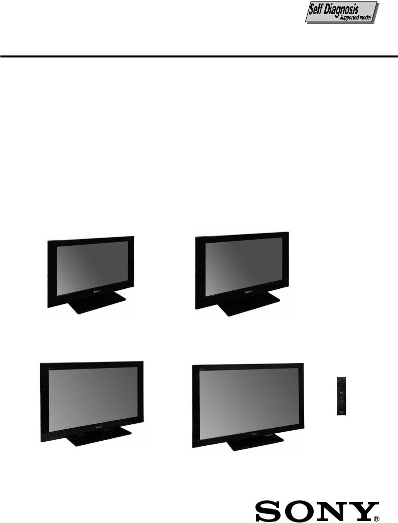
1-3. Leakage Test
The AC leakage from any exposed metal part to earth ground and from all exposed metal parts to any exposed metal part having a return to chassis must not exceed 0.5mA (500 microamperes). Leakage current can be measured by any one of the three methods:-
1.A commercial leakage tester such as the SIMPSON 229 or RCA WT-540A. Follow the manufacturers instructions to use those instructions.
2.A battery-operated AC milliampmeter. The DATA PRECISION 245 digital multimeter is suitable for this job.
3.Measuring the voltage drop across a resistor by means of a VOM or battery operated AC voltmeter. The 'limit' indication is 0.75V so analog meters must have an accurate low voltage scale. The SIMPSON'S 250 and SANWA SH-63TRD are examples of passive VOMs that are suitable. Nearly all battery operated digital multimeters that have a 2 VAC range are suitable. (see Figure 1.)
To Exposed Metal
Parts on Set
AC
0.15 F 1.5 kΩ Voltmeter
(0.75 V)
Earth Ground
Figure 1. AC voltmeter to check AC leakage
1-4. WARNING !
SAFETY-RELATED COMPONENT WARNING! COMPONENTS IDENTIFIED BY SHADING AND MARK ! ON THE EXPLODED VIEWS ARE CRITICAL FOR SAFE OPERATION. REPLACE THESE COMPONENTS WITH SONY PARTS WHOSE PART NUMBERS APPEAR AS SHOWN IN THIS MANUAL OR IN SUPPLEMENTS PUBLISHED BY SONY. CIRCUIT ADJUSTMENTS THAT ARE CRITICAL FOR SAFE OPERATION ARE IDENTIFIED IN THIS MANUAL. FOLLOW THESE PROCEDURES WHENEVER CRITICAL COMPONENTS ARE REPLACED OR IMPROPER OPERATION IS SUSPECTED.
– 3 –
KLV-22, 26, 32 BX300, 40 BX400
RM-GA019
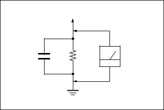
1-5. Lead Free Information
The circuit boards used in these models have been processed using Lead Free Solder. The boards are identified by the LF logo located close to the board designation.
Figure 2: LF logo
Figure 3: LF logo on circuit board
The servicing of these boards requires special precautions. It is strongly recommended to use Lead Free Solder material in order to guarantee optimal quality of new solder joints. Lead Free Solder is available under the following part numbers:-
Part number |
Diameter |
Remarks |
7-640-005-19 |
0.3mm |
0.25Kg |
7-640-005-20 |
0.4mm |
0.50Kg |
7-640-005-21 |
0.5mm |
0.50Kg |
7-640-005-22 |
0.6mm |
0.25Kg |
7-640-005-23 |
0.8mm |
1.00Kg |
7-640-005-24 |
1.0mm |
1.00Kg |
7-640-005-25 |
1.2mm |
1.00Kg |
7-640-005-26 |
1.6mm |
1.00Kg |
Due to high melting point of Lead Free Solder, the soldering iron tip temperature needs to be set to 370 degrees centigrade. This requires soldering equipment capable of accurate temperature control coupled with a good heat recovery characteristics.
For more information on the use of Lead Free Solder, please refer to http://www.sony-training.com
1-6. Attachment & Detachment of MDF61 Connector (If applicable for these models)
a) Insertion
(1) Hold the center of a |
(2) Press the center of the |
(3) Slide the slider to lock the |
connector. |
connector to insert it. |
connector. |
Lock
b) Detachment
(1) Slide the slider to release |
(2) Press the center lock tab |
the slider lock. |
to release the lock and pull |
|
the connector up. |
Unlock
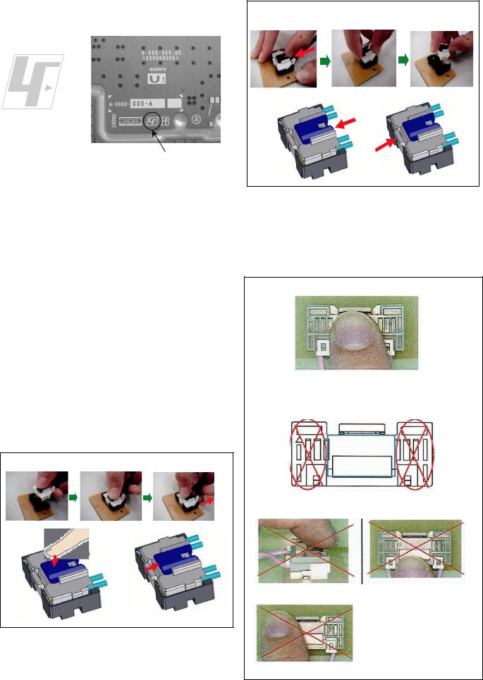
1-7. Attachment, Detachment & Confirmation of Lock Condition of JST IBH Connector
(If applicable for these models)
Attention: This is a SAFETY CRITICAL PROCESS.
a) Attachment
(1) Press the center of the connector to insert it.
(2)Press position
(NG for red marking portion)
(3) Prohibited matter (Refer Figure A~C explanation)
Figure A |
Figure B |
|
Figure A: Do not press lock |
|
portion. |
|
Figure B: Do not press the |
|
front side of the |
|
connector. |
|
Figure C: Do not press the side |
Figure C |
of the connector. |
– 4 –
KLV-22, 26, 32 BX300, 40 BX400
RM-GA019
SECTION 2
SELF DIAGNOSTIC FUNCTION
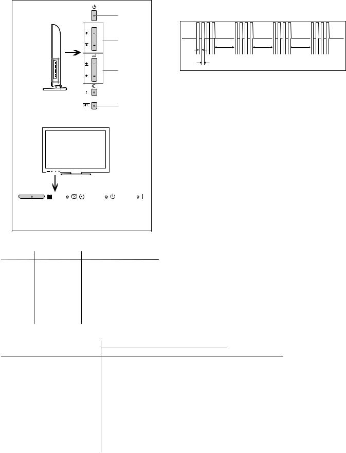
2-1. Overview of Control Buttons |
|
2-4. LED Pattern |
|
|
|
|
When safety shutdown occurs, Standby LED display reports the |
||
|
|
cause by using the lightning patterns as indicated below. |
||
|
Power |
|
|
|
PROG |
|
|
|
|
|
Program |
|
|
|
|
|
3.0 sec |
3.0 sec |
3.0 sec |
|
|
0.5 sec |
|
|
|
Volume |
0.5 sec |
|
|
|
|
|
|
|
|
|
|
Input Select/ |
Example: |
|
|
|||
|
|
|
||
|
|
|
Enter |
|
|
|
|
|
|
|
|
The figure above shows LED display when
Menu SHUTDOWN is caused by Balancer Error. It repeats flashing for a specified number of times in 0.5sec/ cycle and has a 3 seconds interval of lighting off. Please note that a 3 seconds interval of lighting off is fixed regardless of abnormal state types.
|
|
|
|
|
|
|
|
|
|
|
|
|
|
|
|
|
|
|
|
|
|
|
|
|
|
|
|
|
|
|
|
|
|
|
|
|
|
|
|
|
|
|
|
|
|
|
|
|
|
|
|
|
|
|
|
|
|
|
|
|
|
|
|
|
|
|
|
|
|
|
|
|
|
|
|
|
|
|
|
|
|
|
|
|
|
|
|
|
|
|
|
|
|
|
|
|
|
|
|
|
|
|
|
|
|
|
|
|
|
|
|
|
|
|
|
|
|
|
|
|
|
|
|
|
|
|
|
|
|
|
|
|
|
|
|
|
|
|
|
Remote |
|
Picture |
Off/Standby |
Power |
|||||||||||||||
Sensor |
|
Timer |
Indicator |
Indicator |
|||||||||||||||
2-2. LED Display Specification
LED Type |
Description |
Remark |
|
|
|
POWER |
Green: LED |
Green lights at power ON. |
|
|
|
|
|
|
|
|
|
STANDBY |
Red: One LED |
Red lights during standby. |
|
|
|
|
|
|
|
|
|
Timer/ |
Orange/Green : |
Green Lights during Picture |
|
|
|
Two LEDs |
Off and Orange Lights during |
|
|
||
Pic off |
|
|
|||
|
Timer activation. |
|
|
|
|
|
|
|
|
|
|
|
|
|
|
|
|
2-3. LED Display Control |
|
|
|
|
|
|
|
|
|
|
|
Status |
|
|
LED Display |
Remark |
|
|
Power |
Stand By |
Pic Off/Connecting/Timer |
||
|
|
|
|||
Power On |
|
Green |
Off |
Off |
|
|
|
|
|||
Standby |
|
Off |
Red |
Off |
|
Self Diagnosis |
|
Off |
Red |
Off |
Refer to Blinking |
|
|
|
|
|
pattern selfdiagnosis |
|
|
|
|
|
mode |
|
|
|
|
|
|
Error of panel ID |
Green |
Off |
Orange |
0.5sec On / 0.5sec Off |
|
|
|
|
|
|
|
Others (Example) |
|
|
|
|
|
|
|
|
|
|
|
[REC][Sleep Timer][Power ON] |
Red |
Off |
Orange |
|
|
|
|
|
|
||
[Picture Off][On Timer][REC][Power On] Red |
Off |
Green |
|
||
|
|
|
|
|
|
– 5 –
KLV-22, 26, 32 BX300, 40 BX400
RM-GA019
2-5. Standby LED Error Display and Board Replacement Order
Perform below countermeasure according Standby LED blinking times
Blinking times |
Error |
|
Countermeasure |
|
|
|
(Replace either/all according to sequence) |
|
|
|
|
2 |
Main Power Error |
1. GD1 (22”), POWER UNIT(G1LS) (26"), G2LE (32”), |
|
|
|
|
G2HE (40”) |
|
|
2. |
BAA board |
|
|
|
|
3 |
DC_ALERT1/ |
1. BAA board |
|
|
Audio Error/ |
2. GD1 (22”), POWER UNIT(G1LS) (26"),G2LE (32”), |
|
|
Motionflow Error |
|
G2HE (40”) |
|
|
3. TCON |
|
|
|
4. |
Speaker |
|
|
|
|
4 |
Balancer Error |
1. Inverter board |
|
|
|
2. |
Panel |
|
|
3. |
GD1 (22”) , POWER UNIT(G1LS) (26"), G2LE (32”), |
|
|
|
G2HE (40”) |
|
|
4. |
BAA board |
|
|
|
|
5 |
T-CON Error/ |
1. T-CON |
|
|
Panel ID NVM Error |
2. BAA |
|
|
|
3. |
LVDS Cable |
|
|
4. |
GD1 (22”) , POWER UNIT(G1LS) (26"),G2LE (32”), |
|
|
|
G2HE (40”) |
|
|
|
|
6 |
Backlight Error |
1. Inverter board |
|
|
|
2. |
GD1 (22”) , POWER UNIT(G1LS) (26"),G2LE (32”), |
|
|
|
G2HE (40”) |
|
|
3. |
BAA |
7 |
Temp Error |
1. BAA |
|
|
|
2. |
GD1 (22”) , POWER UNIT(G1LS) (26"), G2LE (32”), |
|
|
|
G2HE (40”) |
|
|
|
|
Note1: Each of the above blinking repeats 3 seconds.
Note2: Countermeasure is list out by priority.
– 6 –
KLV-22, 26, 32 BX300, 40 BX400
RM-GA019
|
NoAudio |
|
|
NoHDMI |
|
|
OK 1-3 |
|
missing |
Tuner |
Video |
distoredor |
NoTuner |
VideoOK |
Video |
NoVideo |
BLOK |
|
NoVideo |
NoBL |
|
NoVideo |
BLOK |
|
|
NoPower |
|
|
7Blinks |
Symptom(deadset) |
|
6Blinks |
|
4Blinks 5Blinks |
|
|
|
3Blinks |
|
|
2Blinks |
6.TriageChart |
Reference |
|
2- |
|
|
Bad |
BAAboard BAAboard BAAboard |
|
NoOSD |
BAAboard BAAboard |
|
OSDOK |
BAAboard BAAboard |
|
|
Inverter TemperatureNoPower |
|
|
BAAboard BalancerTCON,PanelID |
Doubtfulpart fewpossibility |
|
NoPower |
|
BAAboard |
GD1(22") G1LS(26") G2LE(32") G2HE(40") GD2(46") T-conboard Speakerunit RFmodule Panelmodule FFCcable Jointconnector Problem |
|
– 7 –
KLV-22, 26, 32 BX300, 40 BX400
RM-GA019
SECTION 3
TROUBLESHOOTING
3.1 FLOWCHART
3-1-1. NO POWER
– 8 –
KLV-22, 26, 32 BX300, 40 BX400
RM-GA019
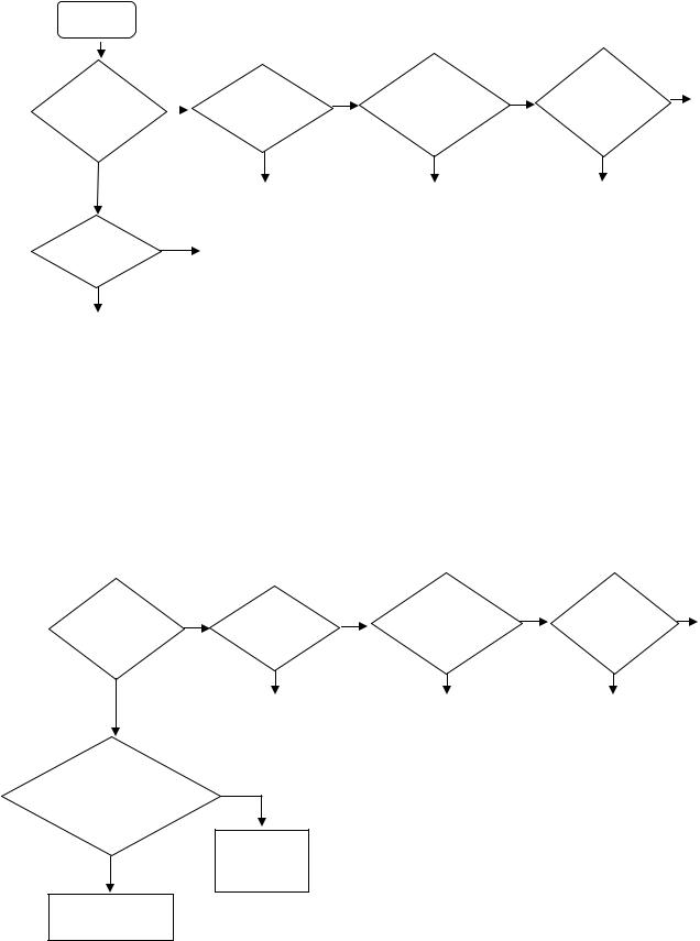
3-1-2. VIDEO PROBLEM
Video
Problem
All inputs |
No |
|
HDMI |
No |
RF/Analog |
No |
Digital |
No |
BAA |
|||
|
Input |
|||||||||||
have |
|
|
Problem? |
|
|
Input |
|
|
Board |
|||
|
|
|
|
|
Problem? |
|
||||||
problem? |
|
|
|
|
|
|
Problem? |
|
|
|
||
|
|
|
|
|
|
|
|
|
|
|
|
|
Yes |
|
|
|
|
Yes |
|
|
Yes |
|
Yes |
|
|
|
|
|
|
|
|
|
|
|
|
|
|
|
|
|
|
|
BAA |
|
|
BAA |
|
BAA |
|
|
|
|
|
|
|
Board |
|
|
Board |
|
Board |
|
|
|
Backlight |
Yes |
|
|
|
|
|
|
|
|
|
||
BAA |
|
|
|
|
|
|
|
|
||||
Turn on? |
|
|
Board |
|
|
|
|
|
|
|
|
|
|
|
|
|
|
|
|
|
|
|
|
||
No |
|
|
|
|
|
|
|
|
|
|
|
|
|
|
|
|
|
|
|
|
|
|
|
|
|
Check LVDS harness |
|
|
|
|
|
|
|
|
|
|
|
|
connection |
|
|
|
|
|
|
|
|
|
|
|
|
between BAA board or |
|
|
|
|
|
|
|
|
|
|
|
|
Panel or Power board |
|
|
|
|
|
|
|
|
|
|
|
|
3-1-3. AUDIO PROBLEM |
|
|
|
|
|
|
|
|
|
|
|
|
|
RF/ Analog |
|
Digital |
|
||
Only |
No |
HDMI |
No |
No |
No |
BAA |
|||
Speaker |
|
Problem? |
|
|
Input |
|
Input |
|
Board |
|
|
|
Problem? |
|
Problem? |
|
|||
out? |
|
|
|
|
|
|
|
||
|
|
|
|
|
|
|
|
|
|
Yes |
|
|
|
|
|
|
|
|
|
|
BAA |
|
|
BAA |
|
BAA |
|
|
|
|
|
|
|
|
|
|
|||
|
|
Board |
|
|
Board |
|
Board |
|
|
|
|
|
|
|
|
|
|
|
|
UI of
Audio Setting Yes correct? Volume,
TV Speaker
Check
No Speaker
BAA board
Set correctly or reset by menu
– 9 –
KLV-22, 26, 32 BX300, 40 BX400
RM-GA019
SECTION 4
SERVICE ADJUSTMENT
4-1. Accessing Self Diagnostic Menu
1.While TV on standby mode, press the following sequence on the Remote commander. (RM-GA019)
< Display--> <5>--> <Vol Down>--> <Power>
|
Self Check |
|
|
|
|
|
|
1 indicates an error was detected |
|||||
|
002 |
|
|
|
Main Power |
001 |
|
||||||
|
|
|
|
|
|
||||||||
|
|
|
|
|
0 indicates no error was detected |
||||||||
|
003 |
|
|
|
Dc_Alert |
|
000 |
|
|||||
|
|
|
|
|
|
|
|||||||
|
003 |
|
|
|
Aud_Prot |
|
000 |
|
|
||||
|
003 |
|
|
|
MotionFlow |
|
000 |
|
|
||||
|
004 |
|
|
|
Balancer_Error |
|
000 |
|
|
||||
|
005 |
|
|
|
T-CON Error |
|
|
|
|
||||
|
005 |
|
|
|
Panel ID NVM Error |
|
000 |
|
|
||||
|
006 |
|
|
|
Backlight Error |
|
000 |
|
|
||||
|
007 |
|
|
|
Temp_Error |
|
000 |
|
|
||||
|
00009 |
|
00027 |
00009 |
|
|
|
Diagnostic Menu Sample |
|||||
|
|
|
|
|
|
|
|
|
|
|
|
||
|
|
|
|
|
|
|
|
|
|
|
|
|
|
|
|
|
|
|
|
|
|
|
|
|
|
|
|
|
|
|
|
|
|
|
|
Total Panel Hours |
|
|
|
|
|
|
|
|
|
|
|
|
|
(max 65535) |
|
|
|
|
|
Total Hours |
|
|
|
|
|
|
|
|
|
|
|
||
of Operation |
|
|
|
Boot Count |
|
|
|
|
|
||||
(max 65535) |
|
|
|
(max 65535) |
|
|
|
|
|
||||
|
|
|
|
|
|
|
|
|
|
|
|
|
|
2. To Reset Error Count & Error History Press < 8 > --> < 0 > key
3. To Reset Panel Operation Time Press < 7 > --> < 0 > key
4. To exit, turn the power off using Remote.
4-2. Accessing Service Mode
1.While TV on standby mode, press the following sequence on the Remote commander.
< Display--> <5>--> <Vol Up>--> <Power>
4-3. GAISOU Adjustment
(NOT APPLICABLE FOR THIS MODEL)
1)When new board is replaced, please confirm the color ornamental of the TV set.
2)While TV on standby mode, press the following sequence on the Remote commander.
<Display> p <5> p <Vol Up> p <Power>
Tuning System |
|
<[Auto]> |
|
Chassis |
Service |
|
|
No_Signal_Mute |
Model |
<[Off]> |
|
Serial Number Edit |
|
|
|
000 |
|
|
|
Self Diagnosis History >> |
|
|
|
002 |
Gaisou |
00 |
|
LVDS Spectrum (%) |
<[10]> |
|
|
Low of HPD |
|
<[5]> |
|
VCR1 |
|
<[off]> |
|
GAISOU Menu |
Sample |
||
GAISOU |
|
<[0]> |
|
Service Mode Menu Sample
3) Use the r or R button to select the GAISOU.
Service Mode |
|
Status Information >> |
|
Test Reset |
<[Off]> |
Tuning System |
<[Auto]> |
No_Signal_Mute |
<[Off]> |
Serial Number Edit |
|
Self Diagnosis History >> |
|
LVDS Spectrum (%) |
<[10]> |
Low of HPD |
<[5]> |
VCR1 |
<[off]> |
GAISOU |
<[0]> |
Service Mode Menu Sample
4)Use the T or t button to change the GAISOU data.
5)The color variation table of each TV set as below:-
Tuning System |
<[Auto]> |
No_Signal_Mute |
<[Off]> |
Serial Number Edit |
|
Self Diagnosis History >> |
|
LVDS Spectrum (%) |
<[10]> |
Low of HPD |
<[5]> |
VCR1 |
<[off]> |
GAISOU |
<[0]> |
Service Mode Menu Sample
2.Use the r or R button to select the item you want to refer
and press  for details. Example Status information
Case |
Color |
Model |
Panel ID |
Area |
|
Table |
Type |
Name |
Resolution |
Inch Size |
ID |
00 |
Default |
5-2 |
WXGA/FHD |
40, 32,26, 22 |
ALL |
01 |
Glossy Gun Metallic (back print) |
3a-2 |
FHD |
32,40,46 |
GA |
02 |
Glossy Silver (back print) |
3a-2 |
WXGA |
22,26,32 |
GA |
03 |
Red |
3a-2 |
FHD |
32 |
GA |
04 |
Blue |
3a-2 |
FHD |
32 |
GA |
05 |
Matt Gun Metallic |
3a-2 |
FHD |
32,40,46 |
CH |
06 |
Flat Gun Metallic Hairline |
3a-1, 3a-0.5 |
HFR/ FHD |
32,40,46,55 |
ALL |
07 |
Silver |
5-0 |
FHD |
32,40 |
ALL |
08 |
Black |
5-0 |
WXGA |
26,32 |
ALL |
6)For example if color is Red than should select 03 in the service mode of the TV set.
Service Mode |
|
|
|
|
|
Status Information >> |
|
|
|
Main Micro |
|
Test Reset |
<[Off]> |
|
|
SW Version |
TM0.341.012 |
Tuning System |
<[Auto]> |
|
|
NVM Version |
TD0.341 |
No_Signal_Mute |
<[Off]> |
|
|
Boot Version |
TB0.341 |
Serial Number Edit |
|
|
|
Panel Version |
MT0000.000.0030.LT |
Self Diagnosis History >> |
|
|
|
Flash PQ Version |
|
LVDS Spectrum (%) |
<[10]> |
|
|
AQ Version |
AQ0.003 |
Low of HPD |
<[5]> |
|
|
|
|
|
|
|
|
|
|
|
|
|
|
|
|
– 10 –
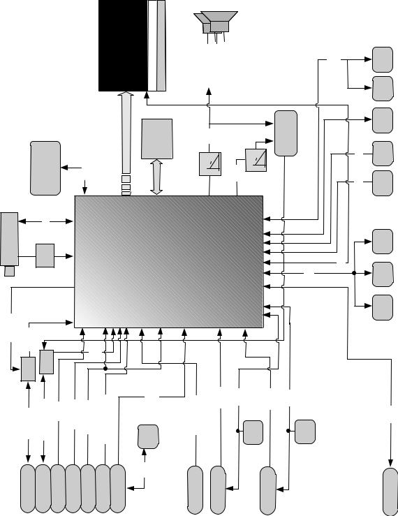
BLOCKDIAGRAM |
1.KLV-22,26,32BX300 |
5-1. |
5-1- |
KLV-22, 26, 32 BX300, 40 BX400
RM-GA019
SECTION 5
DIAGRAMS
|
NAND |
FLASH 64MByte |
|
|
TuI2C |
Tuner |
SAW |
(38Mz) |
CVBSOut |
CVBSIn |
|
|
SW |
SW |
|
|
|
CVBS1/Mon |
Video1/MonL/R |
CVBS2 |
Video1 |
MONOut |
Video1/Mon L/R |
Video2 |
PDD0~7
PANEL 8bit |
(WXGA) |
CCFL |
ConventionalINVERTER |
SingleChannel8bit |
|
Memory |
DDR2 32Mbx16bits |
|
|
16Bit |
|
ChLVDS |
|
I/F |
|
Dual |
|
Memory |
|
 TPA3110D2
PWM |
|
|
LPF |
PWM |
LPF |
outx2ch Audio
NJM2779 AMP outLine
STBY UART0 |
ECS |
|
Hotel UART |
|
JTAG |
LED |
LED |
SIRCS |
SIRCS |
CVBS |
2chxOut |
|
|
|
|
|
MT5388 |
BGA |
|
|
ControI/O |
|
|
I2CM |
PANEL12C |
Main NVM 16KByte |
IFIn |
|
|
|
|
|
|
|
|
|
|
|
|
|
|
Temp Sensor |
|
|
CVBS |
|
Audio |
|
|
YUV |
RGB |
|
TMDS |
|
|
|
|
|
RGB Ambient sensor |
|
|
In x 4ch |
|
In x 7ch |
|
|
In x 2ch |
In x 1ch |
|
In x 3ch |
|
|
|
|
|
|
|
|
In |
L/R |
Comp1/Video3L/R |
|
|
|
|
|
|
|
|
|
|
|
|
|
Video2L/R |
Yuv1/CVBS3 |
|
|
PC |
EDID |
PC/HDMI3L/R |
TMDS0 |
DDC0 |
HDMI1 EDID |
TMDS2 |
DDC2 |
HDMI2 EDID |
|
D+/D- |
||
|
|
|
|
|
RGB |
HV |
|
|
|
|
|
|
|
|
|
|
Video2 L/R |
Component1 /Video3 |
Comp1/Video3 |
L/R |
PC |
DCC |
|
|
PC/HDMI2 L/R |
HDMI1 |
|
|
HDMI2 |
|
|
|
USB1 |
– 11 –
KLV-22, 26, 32 BX300, 40 BX400
RM-GA019
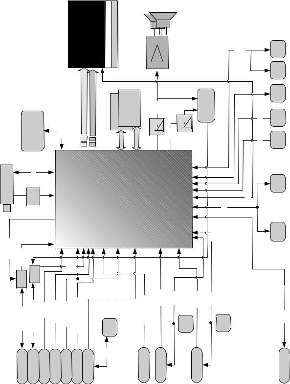
5-1-2. KLV-40BX400
PANEL 8bit |
(FHD) |
CCFL |
ConventionalINVERTER |
TPA3110D2 |
|
|
|
|
OddChannel8bit |
EveChannel8bit |
Memory |
Memory DDR2 32Mx16bits |
NAND |
FLASH |
64MByte |
|
PDD0~7 |
|
16Bit |
16Bit |
|
|
|
|
ChLVDS |
I/F |
|
|
|
|
|
|
|
Dual |
Memory |
|
Tuner |
TuI2C |
CVBS |
2chxOut |
|
MT5388 |
BGA |
|
SAW |
(38Mz) |
|
|||||
|
|
|
IFIn |
|
|
|
|
PWM |
|
LPF |
NJM2779 AMP |
LPF |
PWM |
out |
|
|
|
|
Line |
outx2ch |
|
|
|
Audio |
|
|
|
|
|
ControI/O |
M I2C |
Out |
|
|
|
|
CVBS |
Audio |
|
YUV |
RGB |
|
TMDS |
|
|
|
|
|
|
|
|
|
In x 4ch |
In x 7ch |
|
In x 2ch |
In x 1ch |
|
In x 3ch |
|
|
|
|
||
CVBS |
SWCVBSIn |
SW |
|
|
In |
L/R |
|
|
|
|
|
|
|
|
|
|
|
|
Video1/MonL/R |
CVBS2 |
Video2L/R |
Yuv1/CVBS3 |
Comp1/Video3L/R |
|
RGB |
HV |
PC/HDMI3L/R |
TMDS0 |
DDC0 |
|
TMDS2 |
DDC2 |
|
|
CVBS1/Mon |
|
PC |
EDID |
HDMI1 EDID |
HDMI2 EDID |
||||||||||
|
Video1 MONOut |
Video1/Mon L/R |
Video2 |
Video2 L/R |
Component1 /Video3 |
Comp1/Video3 L/R |
PC |
DCC |
|
PC/HDMI2 L/R |
HDMI1 |
|
|
HDMI2 |
|
|
STBY UART0 |
ECS |
|
Hotel UART |
|
JTAG |
LED |
LED |
SIRCS |
SIRCS |
PANEL 12C |
Temp Sensor |
|
RGB Ambient sensor |
D+/D-
USB1
– 12 –
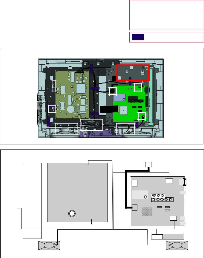
5-2. WIRE DRESSING AND CONNECTOR DIAGRAM
5-2-1. KLV-22BX300
KLV-22, 26, 32 BX300, 40 BX400
RM-GA019
CAUTION :
1.Do not overpull the wires during dressing --> avoid disconnection of wires.
2.Make sure wires are kept away from sharp edges, heatsinks & other high-temperature parts.
Tape (60mm)
A. WIRE DRESSING
|
Insert |
TAPE |
Chassis EF |
|
Connector |
|
|
|
|
|
TAPE |
Insert |
|
TAPE |
MAIN HARNESS |
Connector |
Pink |
|
Insert |
|
|
||
|
|
|
Connector |
|
Blue |
|
Insert Connector |
Insert |
Clamp Edge |
|
|
ConnectorTAPE |
|
|
|
|
Pink |
FLAT FLEXIBLE CABLE |
|
|
Blue |
(FFC) |
|
|
|
|
|
Insert |
Clamp Edge |
TAPE |
|
Connector |
|
|
Insert |
|
|
|
|
TAPE |
|
|
Connector |
|
|
|
|
|
|
Insert |
TAPE |
|
Insert |
Connector |
Insert |
|
|
||
|
Connector |
|
Connector |
B. CONNECTOR DIAGRAM
GD1 |
CN6150 |
(15) |
(STATIC CONVERTER(TV)-GD1-2A) (POWER SUPPLY)
|
|
|
|
|
|
|
Pink |
|
|
|
|
|
|
|
|
|
|
|
|
CN6702 |
|
|
|
|
|
|
|
CNxxxx |
(4) |
|
|
|
(2) |
|
|
|
|
|
|
|
|
|
|
|
|
|
|
|
|
||
|
INVERTER |
|
|
|
|
CN6701 |
|
|
|
|
|
|
|
CNxxxx |
(4) |
|
|
|
CN6703 |
|
|
|
|
|
|
|
|
|
|
|
|
|
(2) |
|
|
|
|
|
|
|
|
|
|
|
|
|
|
|
|
|
|
|
|
|
|
|
|
|
Blue |
|
|
|
|
|
|
|
|
|
|
|
|
Pink |
|
|
|
|
|
|
|
|
|
|
|
|
|
|
|
|
|
|
|
|
|
|
|
|
|
CN6704 |
|
|
|
|
|
CN1/ |
|
|
|
|
|
|
(2) |
|
|
|
|
|
CN100 |
|
|
|
|
|
|
|
|
|
|
|
|
(3) |
|
|
|
|
|
|
(2) |
|
|
|
|
|
|
|
|
|
|
|
|
|
|
|
|
|
|
|
|
|
|
|
|
|
|
|
|
|
|
|
|
|
|
|
|
|
|
Blue |
|
CN6000 |
|
||
|
|
|
|
|
|
|
|
|
(2) |
|
||
H2LS/ SWunit |
|
|
|
|
|
|
|
|
|
|
|
|
|
|
|
|
|
|
|
|
|
|
|
|
|
|
|
|
|
|
|
|
AC Power |
|||||
|
|
|
|
|
|
|
|
|
|
|
|
|
AV_Input/ Power On /Off
|
|
TCON |
|
|
|
(30) |
|
CN6200 |
|
BAA |
CN4000 |
(10) |
Tuner /I/O/ Audio/ HDMI/Micon/ |
||
|
|
|
(4) |
|
|
Power source/DDR/ Main1/ Main2/ |
|
|
|
LVDS/Panel |
|
|
|
|
|
|
|
|
|
|
|
|
|
|
|
|
|
|
|
|
|
|
|
|
|
|
|
|
|
|
|
|
|
|
|
|
|
|
|
|
|
|
|
|
|
|
|
|
|
|
|
|
|
|
|
|
|
|
|
|
|
|
|
|
|
|
|
|
|
|
|
|
|
|
|
|
|
|
|
CN9701 |
(30) |
|
|
|
|
|
|
|
|
|
|
|
|
|
|
|
|
|
|
|
|
|
|
||
|
|
|
|
|
|
|
|
|
|
|
||
|
|
|
|
|
|
|
|
|
|
|
|
|
|
|
|
|
|
|
|
|
|
|
|
|
|
|
|
|
|
|
|
|
|
|
|
|
|
|
CN5600
(30)
LED, Optical Sensor, SIRCS
CN100/CN001
(10/12) H2LR
Speaker R |
Speaker L |
– 13 –
KLV-22, 26, 32 BX300, 40 BX400
RM-GA019
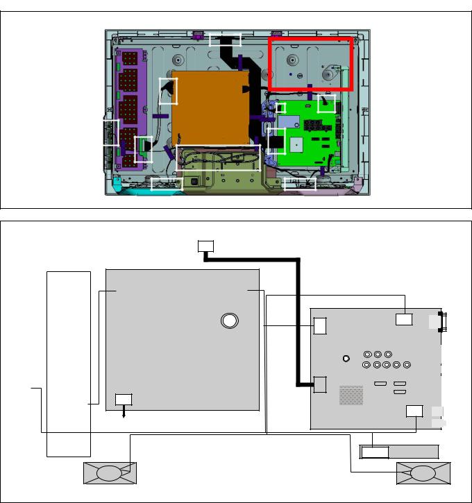
5-2-2. KLV-26BX300
A. WIRE DRESSING
|
|
Do not float the tape |
Chassis EF |
|
||
|
|
Tape |
|
|
||
|
Insert |
|
|
|
|
|
|
Connector |
|
|
|
|
|
|
|
FFC Cable |
Tape |
|
||
|
|
|
|
|
Main Harness |
|
|
|
Do not float the tape |
Insert |
|
||
Insert |
Tape |
|
Tape |
Connector |
|
|
|
|
|
||||
Connector |
|
|
|
|
Tape |
|
|
|
|
|
|
|
|
Insert |
|
|
|
|
|
|
Connector |
|
Tape |
|
|
||
|
|
|
|
|||
Tape |
Tape |
|
|
|
|
|
|
|
Insert |
Insert |
|
||
|
|
Connector |
Connector |
|
||
|
Insert |
|
|
|
Insert |
Tape |
|
Connector |
|
|
|
Connector |
|
|
|
|
|
|
|
|
B. CONNECTOR DIAGRAM
TCON (30)
|
INVERTER |
|
|
||
CN1/ |
||
CN100 |
|
|
(3) |
|
|
H2LS/ SW1 |
|
CNxxxx (14) |
|
|
|
|
|
|
AV_Input/ Power On /Off
POWER UNIT (G1LS)
CN6202 |
(14) |
(POWER SUPPLY) |
|
|
|
CN6000
(2)
AC Power
CN6201 |
(15) |
CN6200 |
|
BAA |
CN4000 |
(10) |
|
(4) |
|
Tuner /I/O/ Audio/ HDMI/Micon/Power |
|||
|
|
source/DDR/ Main1/ Main2/ LVDS/Panel |
|
|
|
|
|
|
|
|
|
|
|
|
|
|
|
|
|
|
|
|
|
|
|
|
|
|
|
|
|
|
|
|
|
|
|
|
|
|
|
|
|
|
|
|
|
|
|
|
|
|
|
|
|
|
|
|
|
|
|
|
|
|
|
|
|
|
|
|
|
|
|
|
|
|
|
|
|
|
|
|
|
|
|
|
|
|
|
|
|
|
|
|
|
|
|
|
|
|
|
|
|
|
|
|
|
|
|
|
|
|
|
|
|
|
|
|
|
|
|
|
|
|
|
|
|
|
|
CN9701 |
(30) |
|
|
|
|
|
|
|
|
|
|
|
|
|
|
|
|
|
|
|
|
|
|
|
|
||
|
|
|
|
|
|
|
|
|
|
|
|||
|
|
|
|
|
|
|
|
|
|
|
|
|
|
|
|
|
|
|
|
|
|
|
|
|
|
|
|
|
|
|
|
|
|
|
|
|
|
|
|
|
|
CN5600
(30)
LED, Optical Sensor, SIRCS
CN100/CN001
(10/12) H2LR/ HLR3
Speaker R |
Speaker L |
– 14 –
KLV-22, 26, 32 BX300, 40 BX400
RM-GA019
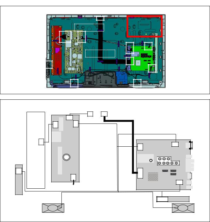
5-2-3. KLV-32BX300
A. WIRE DRESSING
|
|
Insert |
|
|
|
|
Connector |
|
Chassis EF |
|
|
|
|
|
CONNECTOR |
Do not float the tape |
|
|
|
ASSY 14P |
|
Tape |
|
|
|
|
|
|
|
|
Tape |
|
|
|
Tape |
|
Tape |
|
|
|
MAIN HARNESS |
|
Tape |
|
|
Do not float the tape |
Tape |
Insert |
|
|
|
Tape |
|
Connector |
|
|
|
|
|
Insert |
Tape |
FFC Cable |
|
|
|
|
Connector |
|
|
|
|
|
|
|
|
|
|
Tape |
|
Tape |
Tape |
|
|
|
|
|
|
Tape |
|
|
|
Tape |
|
|
|
|
|
|
|
Insert |
Insert |
|
|
|
|
|
|
|
|
Connector |
Connector |
|
|
|
B. CONNECTOR DIAGRAM |
|
|
|
|
|
|
|
|
|
|
|
|
|
|
TCON |
TCON |
|
|
|
|
|
|
|
|
(4) |
(30) |
|
|
|
|
|
|
CN6403 |
|
|
|
|
|
|
|
|
|
(6) |
|
|
|
|
|
|
|
|
CN6402 |
(14) |
CN6401 |
(15) |
|
|
|
|
INVERTER |
CNxxxx (14) |
G2LE |
|
|
CN6200 |
|
BAA |
CN4000 |
|
|
|
(10) |
(4) |
||||||
(POWER SUPPLY) |
Tuner /I/O/ Audio/ HDMI/Micon/ |
||||||||
|
|
|
|
Power source/DDR/ Main1/ |
|||||
|
|
|
|
Main2/ LVDS/Panel |
|
||||
|
|
|
|
|
|
||||
CN1/ |
|
|
|
|
|
CN9700/9701 |
|
|
|
CN100 |
|
|
|
|
|
(51/30) |
|
|
|
(3) |
|
|
|
|
|
|
|
||
|
|
|
CN6101 |
(3) |
|
|
|
||
|
|
|
|
|
|
|
|
|
CN5600 |
H2LS/ SW1 |
|
|
|
|
|
|
|
|
(30) |
|
|
AC Power |
|
|
|
|
|||
|
|
|
|
|
|
|
|
|
|
|
|
|
|
|
|
|
|
LED, Optical Sensor, SIRCS |
|
AV_Input/ Power On /Off |
|
|
|
|
|
|
CN100/CN001 |
H2LR |
|
|
|
|
|
|
|
|
|
(10/12) |
|
|
|
|
|
|
|
|
|
|
|
|
Speaker R |
|
|
|
|
|
Speaker L |
||
– 15 –
KLV-22, 26, 32 BX300, 40 BX400
RM-GA019
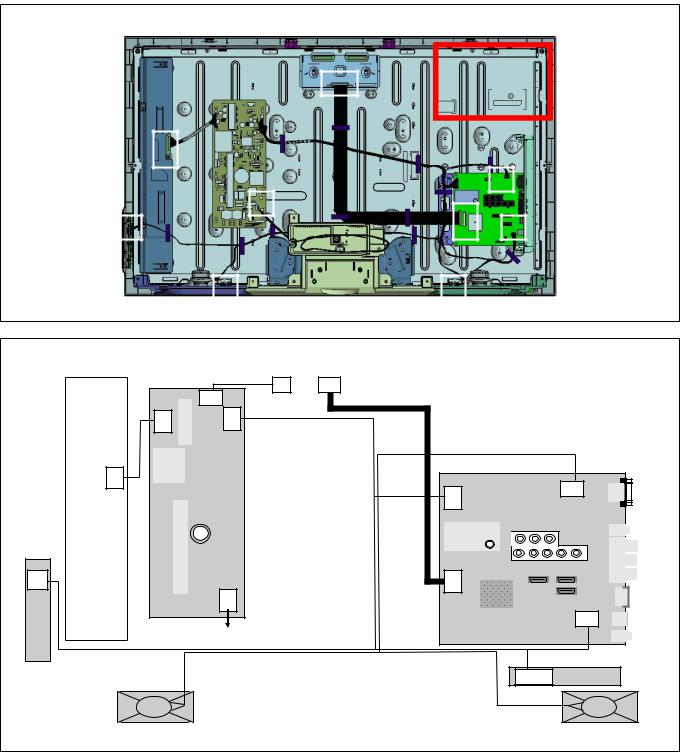
5-2-4. KLV-40BX300
A. WIRE DRESSING
Chassis EF
|
|
|
|
|
Tape |
|
|
|
|
|
|
|
|
|
Tape |
|
|
|
|
|
|
|
|
|
|
|
|
Tape |
Main Harness |
|
||
|
Insert |
|
|
|
|
|
|
|
|
|
|
Connector |
|
Insert |
|
|
|
|
|
|
|
|
|
|
|
|
|
|
|
|
|
|
|
|
|
|
Connector |
|
Tape |
|
|
Insert |
|
|
|
|
|
|
|
|
|
|
||
|
Insert |
|
|
Tape |
FFC Cable |
|
|
Connector |
|
|
|
|
|
|
|
Insert |
|
||||
|
Connector |
|
|
|
|
|
|
|
||
|
|
|
|
|
|
|
Connector |
|
||
|
|
|
|
|
|
|
|
|
|
|
|
|
|
|
|
|
Tape |
|
|
|
|
|
|
Insert |
|
|
|
|
|
|
|
|
|
|
Connector |
|
|
|
Insert |
|
Tape |
|
|
|
|
|
|
|
|
|
|
|
||
|
|
|
|
|
|
|
Connector |
|
|
|
B. CONNECTOR DIAGRAM |
|
|
|
|
|
|
|
|
|
|
|
|
|
|
TCON |
TCON |
|
|
|
|
|
|
|
|
|
(4) |
(51) |
|
|
|
|
|
|
|
CN6403 |
|
|
|
|
|
|
|
|
|
|
(6) |
|
|
|
|
|
|
|
|
|
CN6402 |
(14) |
CN6401 |
(15) |
|
|
|
|
|
|
|
G2HE |
|
|
|
|
|
|
BAA |
CN4000 |
|
|
|
|
|
|
|
|
(4) |
|||
|
|
|
|
|
|
|
|
|||
|
(POWER SUPPLY) |
|
|
|
|
Tuner /I/O/ Audio/ HDMI/Micon/ |
||||
INVERTER |
CNxxxx (14) |
|
|
|
|
|
CN6200 |
(10) |
Power source/DDR/ Main1/ Main2/ |
|
|
|
|
|
|
LVDS/Panel |
|
||||
|
|
|
|
|
|
|
||||
CN1/ |
|
|
|
|
|
|
CN9700 |
(51) |
|
|
CN100 |
|
|
|
|
|
|
|
|
||
(3) |
|
CN6101 |
|
|
|
|
|
|
||
|
|
(3) |
|
|
|
|
|
|
|
|
|
|
|
|
|
|
|
|
|
|
CN5600 |
H2LS/ SW1 |
|
|
|
|
|
|
|
|
|
(30) |
|
AC Power |
|
|
|
|
|
|
|||
|
|
|
|
|
|
|
|
|
|
|
|
|
|
|
|
|
|
|
|
LED, Optical Sensor, SIRCS |
|
AV_Input/ Power On /Off |
|
|
|
|
|
|
|
CN100/CN001 |
H2LR |
|
|
|
|
|
|
|
|
|
|
(10/12) |
|
Speaker R/ Speaker box R |
|
|
|
|
Speaker L/ Speaker box L |
|||||
– 16 –
KLV-22, 26, 32 BX300, 40 BX400
RM-GA019
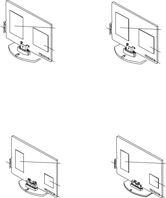
5-3. CIRCUIT BOARD LOCATION |
|
5-3-1 KLV-22BX300 |
5-3-2 KLV-26BX300 |
H2LS Board |
GD1 Board/ |
H2LS Board |
|
|
POWER UNIT (G1LS) Board |
||
|
(STATIC CONVERTER(TV) |
|
|
|
|
|
|
|
-GD1-2A) |
|
|
|
BAA Board |
|
BAA Board |
|
|
|
|
|
H2LR Board |
|
H2LR Board |
|
|
|
5-3-3 KLV-32BX400 |
5-3-4 KLV-40BX400 |
H2LS Board |
G2LE Board |
H2LS Board |
G2HE Board |
|
|
BAA Board |
BAA Board |
H2LR Board |
H2LR Board |
– 17 –

KLV-22, 26, 32 BX300, 40 BX400
RM-GA019
SECTION 6
DISASSEMBLY, EXPLODED VIEW AND OTHER PARTS
Caution:
•! and shaded parts are critical for safety. Replace only with part number specified.
•parts contain confidential information. Strictly follow the instruction whenever the components are repaired and/or replaced.
•Place the TV set facing downwards on a stable, level surface before disassembly and assembly of parts.
Note:
•(*) parts are not stocked since they are seldom required for routine service. Some delays should be anticipated when ordering these components.
•Illustrations provided in this section might have slight difference from the actual sets.
•The reference number besides the part description in the illustration indicates the disassembly sequence.
•Lines that indicate parts are shown in blue in the illustration.
•Only part number and description for service parts are shown in the parts list.
•Unplug connectors before disassembly.
•Refer Electrical Parts List section for connector part number.
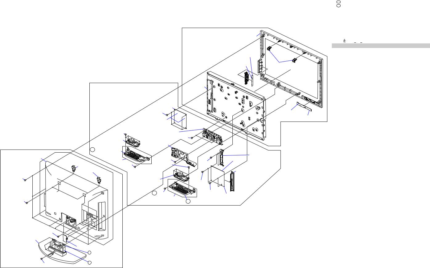
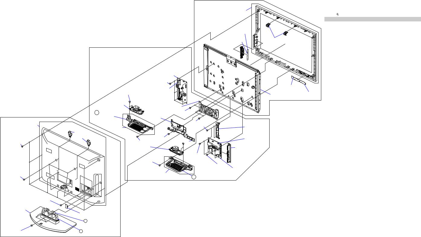
6-1. DISASSEMBLY & EXPLODED VIEW
6-1-1. KLV-22BX300
|
|
|
C. Boards, Panel and Bezel |
Screw: |
|
|
|
REF. NO. |
PART NO. |
DESCRIPTION |
Bezelg (22)Assy |
139qaqdqgqj 28.1 28.2 28.3 |
2-580-640-01 |
SCREW, +BVTP 4X16 TYPE 2 IT-3 |
|
wawswg |
2-580-629-01 |
SCREW, +BVST 3X8 |
|
wjwk |
2-580-590-01 |
SCREW, +PSW M3X5 |
|
4 |
7-685-648-79 |
+BVTP 3X12 TYPE 2 IT-3 |
|
Connectorsed
))
)
A.Stand and Rear Cover Assy
Rear6 Cover
(22) Assy
4 3screws
2 4screws
Cover,7 ECS
Base2 (S3B)Assy
3 1screws
H2LSef Board
28.1 1 screw
B. Boards, Speakers and Frame |
28.2 1 screw |


 Connectorsea 28.3 1 screw

H2LRes Board
|
|
Connectorswf |
|
|
|
LCDe; Panel |
|
|
|
4 wgscrews |
|
2 wkscrews |
|
|
|
|
4 qjscrews |
|
|
|
|
|
|
|
|
|
|
|
Bracket,wl |
Main |
|
Loudspeakerqk |
|
|
|
|
wj |
|
|
|
(4 x 10cm) |
|
|
|
|
2 screws |
|
|
|
|
|
|
|
|
|
Bracketqh |
Speaker (R) |
|
|
|
|
|
|
Plate,8 Vesa |
2 qgscrews |
GD1wh |
Board |
|
|
|
|
|
|
|
|
|
|||
|
|
|
|
|
|
||
|
|
|
|
|
Cover,q; Under |
Connectorsw; |
|
|
|
|
2 |
9screws |
4 qdscrews |
|
|
|
|
|
|
|
|
||
2 wascrews
Loudspeakerqf
(4 x 10cm)
2 screws
BAAwd Complete
Bracketqs |
Speaker (L) |
Bracketql |
Side |
|
|
2 qascrews
 2.1 Neck (S5)
 2.2 Cover, Neck (S3B)
• The reference number beside the part description in the illustration indicates the disassembly sequence.
Parts List:
|
REF. NO. |
PART NO. |
DESCRIPTION |
REMARK |
|
2 |
X-2514-989-1 |
BASE (S3B) ASSY |
|
||
2.1 |
4-158-356-01 |
NECK (S5) |
|
||
2.2 |
4-158-399-01 |
COVER, NECK (S3B) |
|
||
|
|
|
|||
6 |
X-2515-517-1 |
REAR COVER(22) ASSY |
|
||
7 |
4-115-101-41 |
COVER, ECS |
|
||
8 |
4-127-133-01 |
PLATE, VESA |
|
||
0 |
4-157-865-01 |
COVER,UNDER(22) |
|
||
|
qsqh |
4-157-866-01 |
BRACKET, SPEAKER (22L/R) |
|
|
|
qfqk |
1-858-339-11 |
LOUDSPEAKER (4X10CM) |
|
|
|
qk |
4-156-944-51 |
BRACKET, SIDE JACK |
|
|
(BXA-WX)1782wd-(SERVICE)846-A |
( |
|
|
||
STATIC33CONVERTER(TV)wh 1-474-204-GD1-2A |
|
|
|||
|
12 e;(T216XW01V3)! -811-070- |
LCD PANEL (A216V3) |
|
||
|
es |
A-1744-833-A |
H2LR MOUNT |
|
|
|
ef |
A-1744-834-A |
H2LS MOUNT (AZ1A) |
|
|
|
eg |
X-2514-589-1 |
BEZEL (22) ASSY |
|
|
– 18 –
KLV-22, 26, 32 BX300, 40 BX400
RM-GA019
6-1-2. KLV-26BX300
Screw: |
|
|
Parts List: |
|
|
REF. NO. |
PART NO. |
DESCRIPTION |
REF. NO. PART NO. |
DESCRIPTION |
REMARK |
3q;qf |
2-580-640-01 |
SCREW, +BVTP 4X16 TYPE 2 IT-3 |
qlwdwfwh |
2-580-592-01 |
SCREW, +PSW M3X8 |
42-580-595-01 SCREW, +PSW M3X12
15qsqh |
7-685-648-79 |
+BVTP 3X12 TYPE 2 IT-3 |
9wk |
4-159-298-01 |
SCREW, +PSW M4X10 |
B. Boards, Speakers and Frame
|
|
|
|
2 |
X-2546-140-1 |
BASE (M3B) ASSY |
|
|
|
|
2.1 |
4-171-685-01 |
NECK (M3B) |
|
|
|
|
2.2 |
4-171-689-01 |
COVER, NECK (M3B) |
|
|
|
|
6 |
X-2515-518-1 |
REAR COVER(26) ASSY |
|
|
|
|
7 |
4-115-101-41 |
COVER, ECS |
|
|
|
|
0 |
4-157-975-01 |
COVER, UNDER (26) |
C. Boards, Panel and Bezel |
|
|
|
qz |
X-2547-448-1 |
SP BRACKET (26L) ASSY |
|
|
|
qdqj |
1-858-341-11 |
LOUDSPEAKER (4X10CM) |
|
|
|
|
|
qg |
X-2547-449-1 |
SP BRACKET (26R) ASSY |
)) |
INDIA BX30026 |
EXCEPT( |
STATIC CONVERTER1-474-199(TV)w;-12 |
|
|
|
Bezelh |
Assy |
|
|
wa |
4-156-944-51 |
BRACKET, SIDE JACK |
|
|
ERVICE)26 |
|
|||
|
|
A |
BAAwgCOMPLA-1750BXWX-430-32_26 |
|||
|
|
ea |
! 1-811-071-11 |
LCD PANEL (A26V0) |
|
|
|
ed |
A-1744-833-A |
H2LR MOUNT |
|
H2LSeg |
Board |
eg |
A-1744-834-A |
H2LS MOUNT (AZ1A) |
|
eh |
X-2514-590-1 |
BEZEL (26) ASSY |
|||
|
|
||||
ef |
|
Support,e; |
|
|
|
Connectors |
|
Panel |
|
|
|
|
|
|
|
LCDea Panel
Powerw; Unit
|
4 qlscrews |
|
Connectorsqk |
4 qhscrews |
Frame,wl Bottom (SS) |
|
|
Loudspeakerqj |
|
2 wkscrews |
|
|
|
|
A. Stand and Rear Cover Assy |
(4 x 10cm) |
Cover,q; |
Under |
|
|||
15.1 |
Bracket SP (26R) |
(26) |
|
|
|
||
Rear6 Cover (26) Assy |
|
SPqgBracket |
1 9screw |
|
Jointwj Frame Assy |
|
(26R) Assy |
|
ws |
||
|
|
|
2 whscrews |
Connectors |
|
|
Bracket,8 |
1 qfscrew |
4 qsscrews |
|
|
|
|
|
|||
|
|
|
|
|
|
|
Vesa (SS) |
|
|
|
wa |
|
|
|
|
|
Bracket, Side Jack |
103screws |
Loudspeakerqd |
2 wdscrews |
|
(4 x 10cm) |
10.1 |
1 screw |
2 wfscrews |
|
BAAwg Board |
|||
|
SPqaBracket |
||
2 4screws |
Bracket SP (26L) |
||
(26L) Assy 15.1 |
Connectorses
H2LRed Board
2 5screws
Base2 (M3B) Assy
Cover,7 |
ECS |
2.2 Cover, Neck (M3B)
4 |
1screws |
2.1 |
Neck (M3B) |
|
|
• The reference number beside the part description in the illustration indicates the disassembly sequence.
– 19 –
KLV-22, 26, 32 BX300, 40 BX400 |
|
|
|
|
||
|
RM-GA019 |
|
|
|
|
|
6-1-3. KLV-32BX300 |
|
|
|
|
|
|
Screw: |
|
|
Parts List: |
|
|
|
REF. NO. |
PART NO. |
DESCRIPTION |
REF. NO. |
PART NO. |
DESCRIPTION |
REMARK |
|
|
|
|
|||
3qaqg |
2-580-640-01 SCREW, +BVTP 4X16 TYPE 2 IT-3 |
1 |
X-2546-140-1 |
BASE (M3B) ASSY |
|
|
2.1 |
4-171-685-01 |
NECK (M3B) |
|
|||
wawgwhwl |
2-580-592-01 |
SCREW, +PSW M3X8 |
|
|||
2.2 |
4-171-689-01 |
COVER, NECK (M3B) |
|
|||
4 |
2-580-595-01 |
SCREW, +PSW M3X12 |
|
|||
6 |
X-2515-519-1 |
REAR COVER (32) ASSY |
|
|||
15qdqj |
7-685-648-79 +BVTP 3X12 TYPE 2 IT-3 |
|
||||
7 |
4-115-101-41 |
COVER,ECS |
|
|||
9e; |
4-159-298-01 |
SCREW +PSW M4X10 |
|
|||
8 |
4-167-326-01 |
BRACKET, VESA (S) |
|
|||
|
|
|
|
|||
|
|
|
0 |
4-157-976-01 |
COVER, UNDER (32) |
|
|
|
|
0 |
4-169-309-01 |
COVER, UNDER (32) |
|
|
|
|
qs |
X-2547-450-1 |
SP BRACKET (32L) ASSY |
|
|
|
|
qfqk |
1-858-364-11 |
LOUDSPEAKER (12.5.4.5CM) |
|
|
|
|
qh |
X-2547-451-1 |
SP BRACKET (32R) ASSY |
|
|
|
C. Boards, Panel and Bezel ,IRAN(SHAHAB),INDIA32BX300( |
G2LE (UPM) UNITA(-EXCEPT1784-668wa-A |
4-156-944-51 |
BRACKET, SIDE JACK |
|
|
|
|
ws |
|
||
Bezelk Assy
H2LSej Board |
|
Connectorseh |
Support,es |
Panel |
B. Boards, Speakers and Frame
|
|
|
G2LEwa |
Board |
|
|
|
|
|
|
4 w;screws |
|
|
Connectorsef |
|
|
|
Connectorsql |
|
|
|
||
|
|
|
|
LCDed Panel |
H2LReg Board |
||
|
|
|
|
|
|
||
|
|
Loudspeakerqk |
|
|
|
|
|
|
2 qjscrews |
(12.5.4.5cm) Frameea Bottom (S) |
|
|
|
||
|
|
|
|
|
|
|
|
|
|
Cover,q; |
2 e;screws |
|
|
|
|
|
|
|
|
|
|
|
|
A. Stand and Rear Cover Assy |
16.1 Bracket SP (32R) |
Under (32) |
|
Jointwl Frame |
|
|
|
|
SPqhBracket |
|
|
|
|
|
|
Rear6 Cover Assy |
|
|
|
Assy |
|
|
|
(32R) Assy |
|
|
wj |
|
|
|
|
|
|
|
2 screws |
Slide,wk |
|
|
|
|
|
|
|
|
|
|
|
|
1 qgscrew |
|
1 |
9screw |
Clamp |
Connectorswd |
|
|
Bracket,8 |
|
|
|
|
||
|
|
2 qdscrews |
|
|
|
||
|
Vesa (S) |
|
|
|
|
||
103screws |
qf |
Bracket,ws |
Side Jack |
|
Loudspeaker |
|
|
|
(12.5.4.5cm) |
2 wgscrews |
|
|
1 qascrew |
2 wfscrews |
|
2 4screws |
BAAwh Board |
||
SPqsBracket |
|||
12.1 Bracket SP (32L) |
|||
|
|||
2.2 Cover, |
(32L) Assy |
||
|
|
||
Neck (M3B) |
|
|
|
Base2 Assy |
|
|
-A wh84682 |
A-17 BAA COMPL BX_WX_32_26(SERVICE)32BX300 EXCEPT( |
|
15 edLTY320AP04! 1-811-058- |
LCD PANEL (S532TSC) |
|
ed ! 1-811-058-21 |
LCD PANEL (S532TSC) |
|
eg |
A-1744-833-A |
H2LR MOUNT |
ej |
A-1744-834-A |
H2LS MOUNT (AZ1A) |
ek |
X-2514-591-1 |
BEZEL (32) ASSY |
|
|
3 5screws |
|
|
1 |
2.1 |
Neck (M3B) |
Cover,7 |
ECS |
5 screws |
|
|
|
|
• The reference number beside the part description in the illustration indicates the disassembly sequence.
– 20 –
KLV-22, 26, 32 BX300, 40 BX400
RM-GA019
6-1-4. KLV-40BX
Screw: |
Parts List: |
REF. NO. |
|
PART NO. |
DESCRIPTION |
3qaqgwl |
2-580-640-01 SCREW, +BVTP 4X16 TYPE 2 IT-3 |
||
15qdqj |
7-685-648-79 |
+BVTP 3X12 TYPE 2 IT-3 |
|
49e; |
4-159-298-01 |
SCREW +PSW M4X10 |
|
w;wfwgwj |
2-580-592-01 |
SCREW, +PSW M3X8 |
|
C. Boards, Panel and Bezel
REF. NO. |
PART NO. |
DESCRIPTION |
REMARK |
2 2 |
X-2546-141- |
BASE (ML3B) ASSY |
|
6X-2515-520-1 REAR COVER(40) ASSY
7 |
4-115-101-41 COVER, ECS |
84-167-326-01 BRACKET, VESA (S)
04-157-977-01 COVER, UNDER (37)
04-169-308-01 COVER, UNDER (37)
qs |
X-2547-452-1 |
SP BRACKET (40L) ASSY |
qfqk |
1-858-364-11 |
LOUDSPEAKER (12.5X4.5CM) |
qh |
X-2547-453-1 |
SP BRACKET (40R) ASSY |
IRAN) UKRAINE,INDIA, |
40BX400 ( ((EXCEPT |
G2HE (UPM) UNITA-1784wa -672-A |
|
|
|||
Bezelk (40) Assy |
|
|
BX30040 (INDIA))EXCEPT/ |
ws |
4-156-944-51 |
|
BRACKET, SIDE JACK |
|
|
|
A-1784wh-340-A |
BAA COMPL (BX_FHD) (SERVICE) |
|||
|
|
|
|
5 edLTY400HM01! -811-060-1 |
|
LCD PANEL (S40TSP) |
|
|
|
|
|
eg |
A-1744-833-A |
H2LR MOUNT |
|
|
|
|
|
eh |
A-1744-834-A |
H2LS MOUNT (AZ1A) |
|
H2LSej Board |
|
|
|
ej |
X-2514-592-1 |
BEZEL (40) ASSY |
|
|
|
|
|
|
|
|
|
Connectorseh |
Support,es |
Panel |
|
|
|
|
|
|
|
|
|
|
|
|
|
B. Boards, Speakers and Frame
|
|
G2HEwa Board |
|
|
|
|
|
|
5 w;screws |
|
Connectoef |
rs |
|
|
|
Connectorsql |
|
|||
|
|
|
|
|
||
|
2 qjscrews |
|
|
|
LCDed Panel |
H2LReg Board |
|
|
|
|
|
|
|
|
Loudspeakerqk |
Frameea |
Bottom (ML) |
|
|
|
|
(12.5x4.5cm) |
|
|
|||
A. Stand and Rear Cover Assy |
16.1 Bracket |
Cover,q; |
|
2 e;screws |
|
|
|
SP (40R) |
Under (37) |
|
|
|
|
Rear6 Cover (40) Assy |
SPqhBracket |
|
|
2 wlscrews |
|
|
|
|
2 wjscrews |
Bracketwk Joint |
|
||
|
(40L) Assy |
|
|
|
||
|
|
|
|
|
|
|
|
Bracket,8 |
|
|
|
|
|
|
Vesa (S) |
9 |
|
|
Connectorswd |
|
|
|
1 screw |
2 qdscrews |
|
|
|
8 3screws |
|
qg |
|
|
|
|
|
1 screw |
|
|
|
|
|
Loudspeakerqf |
Bracketws |
Side Jack |
(12.5x4.5cm) |
|
|
|
Screws,wg |
|
1 qascrew |
+ PSW M3X8 |
|
|
|
|
|
|
2 wfscrews |
|
|
|
SPqsBracket |
BAAwh Board |
|
4 |
4screws |
|
||
(40L) Assy |
12.1 Bracket SP (40L) |
|||
|
|
|
2 5screws |
Base2 Assy |
Cover,7 ECS |
|
|
|
2.2 Cover, |
|
Neck (ML3B) |
4 1screws |
2.1 Neck (ML3B) |
• The reference number beside the part description in the illustration indicates the disassembly sequence.
– 21 –

KLV-22, 26, 32 BX300, 40 BX400
RM-GA019
6-2. OTHER PARTS
REF NO. PART NO. |
DESCRIPTION |
REMARK |
REF NO. PART NO. |
DESCRIPTION |
REMARK |
6-2-1. KLV-22BX300 |
|
* 1-837-559-11 |
FLAT FLEXIBLE CABLE (FFC) |
|
|
|
|||
|
|
|
CN9701(BAA)-TCON(1) |
|
|
ACCESSORIES AND PACKING |
1-837-735-11 FLAT FLEXIBLE CABLE (FFC) |
||
|
|
CN9701(BAA)-TCON(1) |
||
|
*************************** |
|
||
|
|
|
||
1-569-088-33 |
ADAPTOR,CONVERSION |
*********************************************************************** |
||
|
2P(22BX300(ARM,INDONESIA,IRAN,MALAYSIA, |
|||
|
|
|
||
|
NIGERIA,PHILLIPINES, |
|
MISCELLANEOUS |
|
|
SAUDI ARABIA,SINGAPORE,SOGUL)) |
|
||
|
|
***************** |
||
* 4-170-949-01 |
CARTON, INDIVIDUAL (CON 22) |
|
||
|
|
|||
* 4-170-948-01 |
CUSHION, LOWER (CON 22) |
X-2342-530-2 BAG ASSY, FALL LOCK BELT |
||
* 4-170-947-01 |
CUSHION, UPPER (CON 22) |
|||
2-580-604-01 |
SCREW, +PSW M4X20 |
|||
1-822-631-11 |
PLUG CONVERSION ADAPTOR(22BX300(INDIA)) |
|||
2-580-663-02 |
SCREW, WOOD 3.8X20 |
|||
|
|
|||
1-821-926-11 |
PLUG CONVERSION ADAPTOR |
2-580-608-01 |
SCREW, +PSW M5X16 |
|
|
|
|||
|
(22BX300(TUNISIA, SOUTH AFRICA)) |
*********************************************************************** |
||
4-168-830-11 |
MANUAL, INSTRUCTION (GB) |
|||
|
|
|||
|
(22BX300(ARM,INDIA,INDONESIA,IRAN, |
|
REMOTE COMMANDER |
|
|
MALAYSIA,NEW ZEALAND,NIGERIA, |
|
||
|
|
********************** |
||
|
PHILLIPINES,SAUDIARABIA,SINGAPORE,SOGUL, |
|
||
|
1-487-705-11 |
REMOTE COMMANDER (RM-GA019) |
||
|
SOUTH AFRICA,TUNISIA) |
|||
|
|
|
||
4-168-830-21 |
MANUAL, INSTRUCTION (CS) |
*********************************************************************** |
||
|
(22BX300(ARM,INDONESIA,IRAN,MALAYSIA, |
|||
|
6-2-2. KLV-26BX300 |
|
||
|
NIGERIA,PHILLIPINES,SAUDI ARABIA, |
|
||
|
SINGAPORE,SOGUL)) |
|
|
|
4-168-830-31 |
MANUAL, INSTRUCTION (ARABIC) |
|
ACCESSORIES AND PACKING |
|
|
(22BX300(ARM,INDONESIA,IRAN,MALAYSIA, |
|
*************************** |
|
|
NIGERIA,PHILLIPINES,SAUDI ARABIA, |
|
|
|
|
SINGAPORE,SOGUL,SOUTH AFRICA,TUNISIA)) |
1-56-9-0-33 |
ADAPTOR, CONVERSION 2P |
|
4-168-830-41 |
MANUAL, INSTRUCTION (PERSIAN) |
|
(26BX300(ARM,INDONESIA,IRAN,MALAYSIA, |
|
|
(22BX300(ARM,INDONESIA,IRAN,MALAYSIA, |
|
NIGERIA,PHILLIPINES,SAUDI ARABIA, |
|
|
NIGERIA,PHILLIPINES,SAUDI ARABIA, |
|
SINGAPORE,SOGUL)) |
|
|
SINGAPORE,SOGUL)) |
* 4-170-956-01 |
CARTON, INDIVIDUAL (CON 26) |
|
|
|
* 4-170-954-01 |
CUSHION, LOWER (CYM26) |
|
4-168-830-51 |
MANUAL, INSTRUCTION (RU) |
* 4-170-953-01 |
CUSHION, UPPER (CYM26) |
|
|
(22BX300(ARM,INDIA,IRAN,MALAYSIA, |
4-168-830-11 |
MANUAL, INSTRUCTION (GB) |
|
|
NIGERIA,PHILLIPINES,SAUDI ARABIA, |
|
(26BX300(ARM,INDIA,INDONESIA,IRAN, |
|
|
SINGAPORE,SOGUL,UKRAINE)) |
|
MALAYSIA,NEW ZEALAND,NIGERIA, |
|
4-168-830-61 |
MANUAL, INSTRUCTION (FR) |
|
PHILLIPINES,SAUDIARABIA,SINGAPORE,SOGUL, |
|
|
(22BX300(ARM,INDONESIA,IRAN,MALAYSIA, |
|
SOUTH AFRICA,TUNISIA) |
|
|
NIGERIA,PHILLIPINES,SAUDI ARABIA, |
|
|
|
|
SINGAPORE,SOGUL,SOUTH AFRICA,TUNISIA)) |
4-168-830-21 |
MANUAL, INSTRUCTION (CS) |
|
4-168-830-71 |
MANUAL, INSTRUCTION (UA) |
|
(26BX300(ARM,INDONESIA,IRAN,MALAYSIA, |
|
|
(22BX300(UKRAINE)) |
|
NIGERIA,PHILLIPINES,SAUDI ARABIA, |
|
4-168-830-91 |
MANUAL, INSTRUCTION (TH) |
|
SINGAPORE,SOGUL)) |
|
|
(22BX300(THAILAND)) |
4-168-830-31 |
MANUAL, INSTRUCTION (ARABIC) |
|
1-837-454-11 |
POWER-SUPPLY CORD |
|
(26BX300(ARM,INDONESIA,IRAN,MALAYSIA, |
|
|
(EXCEPT 22BX300(NEW ZEALAND, THAILAND) |
|
NIGERIA,PHILLIPINES,SAUDI ARABIA, |
|
|
|
|
SINGAPORE,SOGUL,SOUTH AFRICA,TUNISIA)) |
|
1-837-459-11 |
POWERSUPPLYCORD(WITHCONNECTOR) |
4-168-830-41 |
MANUAL, INSTRUCTION (PERSIAN) |
|
|
(22BX300(New Zealand)) |
|
(26BX300(ARM,INDONESIA,IRAN,MALAYSIA, |
|
1-837-460-11 |
POWERSUPPLYCORD(WITHCONNECTOR) |
|
NIGERIA,PHILLIPINES,SAUDI ARABIA, |
|
|
(22BX300(THAILAND)) |
|
SINGAPORE,SOGUL)) |
|
|
|
4-168-830-51 |
MANUAL, INSTRUCTION (RU) |
|
|
|
|
(26BX300(ARM,INDIA,IRAN,MALAYSIA, |
|
************************************************************************ |
|
NIGERIA,PHILLIPINES,SAUDI ARABIA, |
||
|
|
|
SINGAPORE,SOGUL,UKRAINE)) |
|
|
CONNECTORS |
4-168-830-61 |
MANUAL, INSTRUCTION (FR) |
|
|
************** |
|
(26BX300(ARM,INDONESIA,IRAN,MALAYSIA, |
|
|
|
|
NIGERIA,PHILLIPINES,SAUDI ARABIA, |
|
* 1-910-059-57 |
MAIN HARNESS |
|
SINGAPORE,SOGUL,SOUTH AFRICA,TUNISIA)) |
|
|
(22BX300(INDIA),22BX300(SOGUL,IRAN, |
|
|
|
|
NIGERIA,SAUDI ARABIA,MALAYSIA, |
4-168-830-71 |
MANUAL, INSTRUCTION (UA) |
|
|
SINGAPORE,ARM,INDONESIA,PHILLIPINES), |
|
(26BX300(UKRAINE)) |
|
|
(THAILAND)) |
4-168-830-91 |
MANUAL, INSTRUCTION (TH) |
|
|
CN6200(BAA)-CN6150(GD1)- |
|
(26BX300(THAILAND)) |
|
|
CN5600(BAA)-CN100(H2LR)- |
1-822-631-11 |
PLUG CONVERSION ADAPTOR(26BX300(India)) |
|
|
CN1(H2LS)CN4000(BAA)-SP(1) |
1-821-926-11 |
PLUG CONVERSION ADAPTOR |
|
* 1-910-800-01 |
MAIN HARNESS(22BX300(NEWZEALAND), |
|
(26BX300(SOUTH AFRICA,TUNISIA) |
|
|
22BX300(RUSSIA),22BX300(SOUTH AFRICA)) |
1-837-454-11 |
POWER-SUPPLY CORD |
|
|
CN6200(BAA)-CN6150(GD1)-CN5600(BAA)- |
|
(EXCEPT 26BX300 (New Zealand,Thailand)) |
|
|
CN100(H2LR)-CN1(H2LS)CN4000(BAA)-SP(1) |
|
|
|
– 22 –

KLV-22, 26, 32 BX300, 40 BX400
RM-GA019
REF NO. |
PART NO. |
DESCRIPTION |
REMARK |
REF NO. |
PART NO. |
DESCRIPTION |
REMARK |
|
1-837-459-11 |
POWERSUPPLYCORD(WITHCONNECTOR) |
|
4-168-830-31 |
MANUAL, INSTRUCTION(AR) |
||
|
|
(26BX300(New Zealand)) |
|
|
|
(32BX300((ARM,INDONESIA,IRAN(SOEM),MALAYSIA, |
|
|
1-837-460-11 |
POWERSUPPLYCORD(WITHCONNECTOR) |
|
|
NIGERIA,PHILLIPINES,SAUDI ARABIA, |
||
|
|
(26BX300(Thailand)) |
|
|
|
SINGAPORE,SOGUL,SOUTH AFRICA,TUNISA) |
|
|
|
|
|
|
4-168-830-41 |
MANUAL, INSTRUCTION(PR) |
|
************************************************************************ |
|
|
(32BX300((ARM,INDONESIA,IRAN(SOEM),MALAYSIA, |
||||
|
|
|
|
|
|
NIGERIA,PHILLIPINES,SAUDI ARABIA, |
|
|
|
CONNECTORS |
|
|
|
SINGAPORE,SOGUL)) |
|
|
|
************** |
|
|
4-168-830-51 |
MANUAL, INSTRUCTION(RU) |
|
|
|
|
|
|
|
(32BX300((ARM,INDONESIA,IRAN(SOEM),MALAYSIA, |
|
* |
1-837-560-11 |
FLAT FLEXIBLE CABLE (FFC) |
|
|
NIGERIA,PHILLIPINES,SAUDI ARABIA, |
||
|
|
(CN9701(BAA)-TCON(1)) |
|
|
|
SINGAPORE,SOGUL),(UKRAINE)) |
|
* |
1-837-736-11 |
FLAT FLEXIBLE CABLE (FFC) |
|
|
|
|
|
|
|
(CN9701(BAA)-TCON(1)) |
|
|
4-168-830-61 |
MANUAL, INSTRUCTION(FR) |
|
* 1-910-059-59 |
CONNECTOR ASSY 14P CN6202(G1LS)-INV(1) |
|
|
(32BX300((ARM,INDONESIA,IRAN(SOEM), |
|||
* 1-910-059-58 |
MAIN HARNESS |
|
|
|
MALAYSIA,NIGERIA,PHILLIPINES, |
||
|
|
CN6200(BAA)-CN6201(G1LS)-CN5600(BAA)- |
|
|
SAUDI ARABIA,SINGAPORE,SOGUL), |
||
|
|
CN100(H2LR)-CN1(H2LS) CN4000(BAA)-SP(1) |
|
|
(SOUTH AFRICA,TUNISIA)) |
|
|
|
|
(26BX300(INDIA),26BX300(SOUTH AFRICA, |
|
4-168-830-71 |
MANUAL, INSTRUCTION(UA) |
||
|
|
TUNISIA),26BX300(THAILAND)) |
|
|
(32BX300(UKRAINE)) |
|
|
* |
1-910-800-02 |
MAIN HARNESS(CN6200(BAA)-CN6201(G1LS)- |
|
4-168-830-91 |
MANUAL, INSTRUCTION(TH) |
||
|
|
CN5600(BAA)-CN100(H2LR)-CN1(H2LS) |
|
|
(32BX300(THAILAND)) |
|
|
|
|
CN4000(BAA)-SP(1)) |
|
|
4-168-830-81 |
MANUAL, INSTRUCTION(VN) |
|
|
|
(26BX300(NEW ZEALAND),26BX300(UKRAINE), |
|
|
(32BX300(PHILLIPINES,VIETNAM)) |
||
|
|
26BX300(SOGUL,IRAN,NIGERIA, |
|
1-822-631-11 |
PLUG CONVERSION ADAPTOR(32BX300(INDIA)) |
||
|
|
SAUDI ARABIA,MALAYSIA,SINGAPORE, |
|
|
|
|
|
|
|
ARM,INDONESIA,PHILLIPINES)) |
|
1-821-926-11 |
PLUG CONVERSION ADAPTOR |
||
|
|
|
|
|
|
(32BX300(SOUTH AFRICA,TUNISIA)) |
|
*********************************************************************** |
|
1-837-454-11 |
POWER SUPPLY CORD |
|
|||
|
|
|
|
|
|
(EXCEPT 32BX300(THAILAND) |
|
|
|
MISCELLANEOUS |
|
|
1-837-460-11 |
POWER SUPPLY CORD (WITH CONNECTOR) |
|
|
|
***************** |
|
|
|
(32BX300(THAILAND)) |
|
|
X-2342-530-2 |
BAG ASSY, FALL LOCK BELT |
*********************************************************************** |
||||
|
2-580-604-01 |
SCREW, +PSW M4X20 |
|
|
|
|
|
|
2-580-663-02 |
SCREW, WOOD 3.8X20 |
|
|
|
CONNECTORS |
|
|
2-580-608-01 |
SCREW, +PSW M5X16 |
|
|
|
************** |
|
|
|
|
|
* 1-910-059-62 |
CONNECTOR ASSY 14PCN6402(G2LE)-INV(1) |
||
*********************************************************************** |
* |
1-910-059-61 |
MAIN HARNESS |
|
|||
|
|
|
|
|
|
CN6200(BAA)-CN6401(G2LE)-CN5600(BAA)- |
|
|
|
REMOTE COMMANDER |
|
|
|
CN100(H2LR)-CN1(H2LS)CN4000(BAA)-SP(1) |
|
|
|
********************** |
|
* |
1-837-561-11 |
FLAT FLEXIBLE CABLE (FFC) |
|
|
|
|
|
|
|
CN9701(BAA)-TCON(1) |
|
|
1-487-705-11 |
REMOTE COMMANDER (RM-GA019) |
|
|
|
|
|
|
|
|
|
*********************************************************************** |
|||
************************************************************************ |
|
|
|
|
|||
6-2-3. KLV-32BX300 |
|
|
|
MISCELLANEOUS |
|
||
|
|
|
|
|
|
|
|
|
|
|
|
|
|
***************** |
|
|
|
ACCESSORIES AND PACKING |
|
X-2342-530-2 BAG ASSY, FALL LOCK BELT |
|||
|
|
*************************** |
|
||||
|
|
|
2-580-608-01 |
SCREW, +PSW M5X16 |
|
||
|
|
|
|
|
|
||
|
1-569-008-33 |
ADAPTOR, CONVERSION 2P |
|
2-580-604-01 |
SCREW, +PSW M4X20 |
|
|
|
|
2-580-663-02 |
SCREW, WOOD 3.8X20 |
|
|||
|
|
(32BX300(ARM,INDONESIA,IRAN(SOEM),MALAYSIA, |
|
|
|||
|
|
|
|
|
|
||
|
|
NIGERIA,PHILLIPINES,SAUDI ARABIA, |
************************************************************************ |
||||
|
|
SINGAPORE,SOGUL), |
|
||||
|
|
|
|
|
|
|
|
|
|
(PHILLIPINES,VIETNAM)) |
|
|
|
HEAT SINK |
|
* |
4-170-960-01 |
CARTON, INDIVIDUAL (CON 32) |
|
|
|
||
|
|
*********** |
|
||||
|
|
(EXCPT 32BX300(IRAN(SHAHAB))) |
|
|
|
||
|
|
|
|
|
|
||
* |
4-176-339-01 |
CARTON, INDIVIDUAL (CON 32) (32BX300(IRAN(SHAHAB)) |
6-503-050-01 |
DI SBT80-06 |
|
||
* 4-170-958-01 |
CUSHION, LOWER (CYM32) |
|
|
||||
|
8-719-510-53 |
DIODE D4SB60L |
|
||||
* |
4-170-957-01 |
CUSHION, UPPER (CYM32) |
|
|
|
||
|
|
6-552-205-11 |
TR TK15A50D |
|
|||
|
|
|
|
|
|
||
|
4-168-830-11 |
MANUAL, INSTRUCTION(GB) |
|
6-552-461-11 |
TR TK5A50D(S4SONY,Q) |
|
|
|
|
|
|
|
|||
|
|
32BX300((ARM,INDIA,INDONESIA, |
*********************************************************************** |
||||
|
|
IRAN(SOEM),MALAYSIA,NIGERIA,PHILLIPINES, |
|||||
|
|
|
|
|
|
||
|
|
SAUDI ARABIA,SINGAPORE,SOGUL, |
|
|
REMOTE COMMANDER |
|
|
|
|
SOUTH AFRICA,TUNISA), |
|
|
|
|
|
|
|
|
|
|
********************** |
|
|
|
|
(PHILLIPINES,VIETNAM)) |
|
|
|
|
|
|
|
|
|
|
|
|
|
|
4-168-830-21 |
MANUAL, INSTRUCTION(CS) |
|
1-487-705-11 |
REMOTE COMMANDER (RM-GA019) |
||
|
|
(32BX300((ARM,INDONESIA,IRAN(SOEM),MALAYSIA, |
|||||
|
|
|
|
|
|||
|
|
NIGERIA,PHILLIPINES,SAUDI ARABIA, |
*********************************************************************** |
||||
|
|
SINGAPORE,SOGUL)) |
|
||||
|
|
|
|
|
|
|
|
– 23 –

KLV-22, 26, 32 BX300, 40 BX400
RM-GA019
REF NO. PART NO. |
DESCRIPTION |
REMARK |
6-2-4. KLV-40BX400
ACCESSORIES AND PACKING
***************************
1-569-033 ADAPTOR, CONVERSION 2P (40BX400(ARM,INDONESIA,IRAN,MALAYSIA, SAUDI ARABIA,SOGUL,VIETNAM,PHILLIPINES)
*4-170-964-01 CARTON, INDIVIDUAL (CON 40)
*4-170-962-01 CUSHION, LOWER (CYM40)
*4-170-961-01 CUSHION, UPPER (CYM40) 4-168-830-11 MANUAL, INSTRUCTION(GB)
(40BX400(ARM,INDONESIA,IRAN,MALAYSIA, NIGERIA,PHILLIPINES,SAUDI ARABIA, SINGAPORE,SOGUL,TUNISIA,VIETNAM))
4-168-830-21 MANUAL, INSTRUCTION(CS) (40BX400(ARM,INDONESIA,IRAN,MALAYSIA, NIGERIA,PHILLIPINES,SAUDI ARABIA, SINGAPORE,SOGUL,VIETNAM))
4-168-830-31 MANUAL, INSTRUCTION(AR) (40BX400(ARM,INDONESIA,IRAN,MALAYSIA, NIGERIA,PHILLIPINES,SAUDI ARABIA, SINGAPORE,SOGUL,TUNISIA,VIETNAM))
4-168-830-41 MANUAL, INSTRUCTION(PR) (40BX400(ARM,INDONESIA,IRAN,MALAYSIA, NIGERIA,PHILLIPINES,SAUDI ARABIA, SINGAPORE,SOGUL,VIETNAM))
4-168-830-51 MANUAL, INSTRUCTION(RU) (40BX400(ARM,INDONESIA,IRAN,MALAYSIA, NIGERIA,PHILLIPINES,UKRAINE,SAUDI ARABIA, SINGAPORE,SOGUL,VIETNAM),
4-168-830-61 MANUAL, INSTRUCTION(FR)( 40BX400(ARM,INDONESIA,IRAN,MALAYSIA, NIGERIA,PHILLIPINES,UKRAINE,SAUDI ARABIA, SINGAPORE,SOGUL,TUNISIA,VIETNAM))
4-168-830-81 MANUAL, INSTRUCTION(VN) (40BX400(ARM,INDONESIA,IRAN,MALAYSIA, NIGERIA,PHILLIPINES,SAUDI ARABIA, SINGAPORE,SOGUL,VIETNAM),
4-168-830-71 MANUAL, INSTRUCTION(UA) (40BX400(UKRAINE))
4-168-830-91 MANUAL, INSTRUCTION(TH) (40BX400(THAILAND))
1-821-926-11 PLUG CONVERSION ADAPTOR (40BX400(TUNISIA))
1-822-631-11 PLUG CONVERSION ADAPTOR(40BX400 (India))
1-837-454-11 POWER-SUPPLY CORD (40BX400(India),40BX400(SOGUL,IRAN,NIGERIA, SAUDIAARABIA,MALAYSIA,SINGAPORE,ARM, INDONESIA,VIETNAM,PHILLIPINES), 40BX400(UKRAINE),40BX400(TUNISIA))
1-837-460-11 POWER SUPPLY CORD(WITHCONNECTOR) (40BX400 (THAILAND)
***********************************************************************
REF NO. PART NO. |
DESCRIPTION |
REMARK |
CONNECTORS
**************
*1-910-059-67 CONNECTOR ASSY 14P
*1-837-731-11 FFC WITH CONNECTOR (CN9700(BAA)-TCON(1))
*1-910-059-66 MAIN HARNESS
(CN6200(BAA)-CN6401(G2HE)-CN5600(BAA)-
CN100(H2LR)-CN1(H2LS), CN4000(BAA)-SP(1)) 40BX400 (SOGUL,IRAN,NIGERIA,SAUDI ARABIA,MALAYSIA,SINGAPORE,ARM, INDOENSIA,VIETNAM,PHILLIPINES,THAILAND)
* 1-910-800-08 MAIN HARNESS (CN6200(BAA)-CN6401(G2HE)-CN5600(BAA)- CN100(H2LR)-CN1(H2LS) CN4000(BAA)-SP(1)) 40BX400(UKRAINE,TUNISIA)
************************************************************************
MISCELLANEOUS
*****************
X-2348-140-3 BAG ASSY, FALL LOCK BELT 2-580-604-01 SCREW, +PSW M4X20 2-580-663-02 SCREW, WOOD 3.8X20 2-580-608-01 SCREW, +PSW M5X16
***********************************************************************
|
HEAT SINK |
|
*********** |
6-503-066-01 |
DI SF5K60M |
6-503-052-01 |
DI SG30SC4M |
6-503-053-01 |
DI STTH5L06FP |
8-719-510-53 |
DIODE D4SB60L |
6-552-205-11 |
TR TK15A50D |
6-552-204-11 |
TR TK8A50D(40BX400) |
***********************************************************************
REMOTE COMMANDER
**********************
1-487-705-11 REMOTE COMMANDER (RM-GA019)
– 24 –
MODEL |
COMMANDER |
DEST |
MODEL |
COMMANDER |
DEST |
KLV-22BX300/1 RM-GA019 |
SOGUL, NIGERIA, |
KLV-26BX300/1 RM-GA019 |
SOGUL, NIGERIA, |
||
|
|
SAUDI ARABIA |
|
|
SAUDI ARABIA |
KLV-22BX300/3 RM-GA019 |
SOGUL,NIGERIA, |
KLV-26BX300/3 RM-GA019 |
SOGUL,NIGERIA, |
||
|
|
SAUDI ARABIA |
|
|
SAUDI ARABIA |
|
|
|
|
|
|
|
|
|
|
|
|
SUBJECT : NEW MODEL ADDITION
This supplement shows variant information for the new model (s).
Other information remain the same as original issue.
KLV-22 BX300/1, BX300/3 |
KLV-26 BX300/1, BX300/3 |
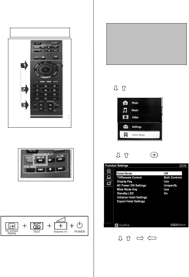
Section 4 : Service Adjustments
4-4 : Hotel Mode Adjustment
4-4-1 : Preset "Test" Button on Remote Commander
1.Press the following buttons in sequence on the Remote and keep pressed for 5 seconds.
Press <Info>Channel 5 Volume (+)
i+
5
Vol
+
2.While the TV turns ON, the indication ‘Hotel Mode Setting in process” appears on the top of the screen.
*It will appear only few seconds.
Hotel Mode Settings in process
Figure 3 : Hotel Model Setting Message screen
3.Press “MENU” button on remote control.
4.The following menu appears on screen.
5. Press / on the Remote and select Hotel Mode.
Figure 1 : To Reset Test Button
2. Once completed, the below button operates as a TEST button.
Figure 2: TEST button
4-4-2 : Entering Hotel Menu Mode
1.While TV set in on standby, press the following sequence on the remote.
Figure 4 : Hotel Model Screen
6. Press “MENU” button on remote control.
7. Press / and press on remote control
8. The following menu appears on screen.
Figure 5: Sample of screen
9. Press / or |
/ |
on the |
Remote for adjustments.
10. REMINDER: PLEASE REFER TO EACH SETTING BEFORE CHANGING HOTEL MODE TO :”ON”. ONCE TURNED “ON” THE HOTEL MODE WILL START.
Details of each setting is on next pages.
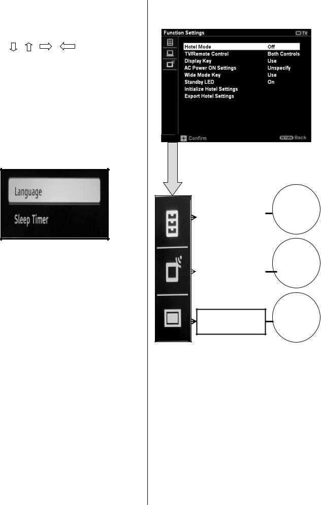
4-4-2 : Entering Hotel Menu Mode
(continue)
11. Press / or / and  on the Remote for adjustments.
12. After done go to Functions settings Hotel Mode and select to" ON”.
13.The TV set resets and restarts.
14. Now press “MENU" on the remote commander.
15. The following menu appears confirms the hotel mode in ON.
Figure: 6
4-4-3 : Hotel Mode Settings Menu Tree
Figure: 7: Sample of screen
|
Menu Items |
|
|
||
Function Settings |
Refer to |
|
4-4-4 |
||
|
Menu Items |
|
|
||
Signal Source |
Refer to |
|
4-4-5 |
||
Settings |
||
|
||
|
|
Menu Items
TV Settings Refer to
4-4-6
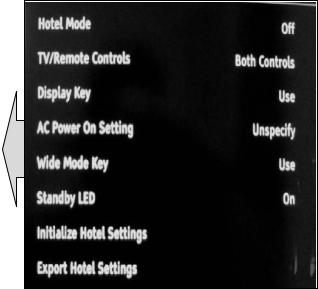
4-4-4 : Menu items in Function Settings
Display |
Options |
Description |
|
|
string |
|
|
|
|
|
|
|
|
|
|
|
|
|
|
Hotel |
On |
This will turn the Hotel |
|
|
Mode |
|
mode on. |
|
|
|
|
|
||
|
|
Tip: This should be the |
|
|
|
|
last setting you do – once |
|
|
|
Off |
turned to “ON” the Hotel |
|
|
|
|
mode will start. |
|
|
|
|
|
|
|
TV/Remote |
Both |
Select whether you want |
|
|
Controls |
Controls |
to the TV to be controlled |
|
|
|
|
by the remote control |
|
|
|
Remote |
|
|
|
|
(RC) or by both controls |
|
|
|
|
Only |
meaning the buttons on |
|
|
|
|
the TV and the RC. |
|
|
|
No Controls |
|
|
|
|
|
|
|
|
|
|
|
|
|
Display Key |
Use |
Select whether you want |
|
|
|
|
to control the display |
|
|
|
|
|
|
|
|
Not Use |
info by the display key |
|
|
|
button on the RC. |
|
|
|
|
|
(Display Key = Info Key) |
|
|
|
|
|
|
|
AC Power |
Unspecify |
Select whether the TV will |
|
|
On Setting |
|
follow last power |
|
|
|
|
|
||
|
Always On |
memory or always turn |
|
|
|
ON after AC Plug Off |
|
|
|
|
|
|
|
|
|
|
|
|
|
Wide |
Use |
Select whether the screen |
|
|
Mode Key |
|
format key can be used or |
|
|
Not Use |
|
|
||
|
not. |
|
|
|
|
|
|
|
|
|
|
|
|
|
Standby |
On |
Select whether you want |
|
|
LED |
|
the standby LED to be on |
|
|
|
|
|
||
|
Off |
or off during standby |
|
|
|
mode |
|
|
|
|
|
|
|
|
|
|
|
|
|
Initialize |
Start |
All settings in Hotel Mode |
|
|
Hotel |
|
Go back to the default |
|
|
Cancel |
|
|
||
Settings |
value |
|
|
|
|
|
|
||
|
|
|
|
|
Export |
|
Select this to export |
|
|
Hotel |
|
“Hotel Mode” settings |
|
|
Settings |
|
done in the “Hotel Menu |
|
|
|
|
Mode” for cloning |
|
|
|
|
function |
|
|
|
|
|
|
|
=Default Settings
Figure: 8
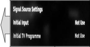
4-4-5 : Menu items in Signal Source Settings
Display string |
Options |
|
Description |
|
|
|
|
|
|||
|
|
|
|
|
|
|
|
|
|
|
|
Signal Source |
TV |
Use / Not |
Define which |
|
|
Settings |
|
Use |
input source |
|
|
|
|
|
should be |
|
|
|
HDMI 1/2/3 |
Use with |
|
|
|
|
available during |
|
|
||
|
|
Labels |
|
|
|
|
|
Hotel Mode. |
|
|
|
|
|
/Use |
|
|
|
|
|
|
|
|
|
|
|
Without |
Note: The |
|
|
|
|
Labels |
|
|
|
|
|
number of |
|
|
|
|
|
/Not Use |
|
|
|
|
|
terminals vary |
|
|
|
|
|
|
|
|
|
|
Video 1/2 |
Use with |
|
|
|
|
by models. |
|
|
||
|
|
Labels |
|
|
|
|
|
/Use |
|
|
|
|
|
Without |
|
|
|
|
|
Labels |
|
|
|
|
|
/Not Use |
|
|
|
|
|
|
|
|
|
|
Component |
Use with |
|
|
|
|
|
Labels |
|
|
|
|
|
/Use |
|
|
|
|
|
Without |
|
|
|
|
|
Labels |
|
|
|
|
|
/Not Use |
|
|
|
|
|
|
|
|
|
|
PC |
Use with |
|
|
|
|
|
Labels |
|
|
|
|
|
/Use |
|
|
|
|
|
Without |
|
|
|
|
|
Labels |
|
|
|
|
|
/Not Use |
|
|
|
|
|
|
|
|
|
Initial Input |
Not Use |
|
Define which |
|
|
|
|
|
should be the |
|
|
|
TV |
|
|
|
|
|
|
initial input |
|
|
|
|
|
|
|
|
|
|
|
|
source when |
|
|
|
HDMI 1/2/3 |
|
|
|
|
|
|
the TV is turned |
|
|
|
|
|
|
|
|
|
|
|
|
on by a hotel |
|
|
|
Video 1/2 |
|
|
|
|
|
|
guest. |
|
|
|
|
|
|
|
|
|
|
Component |
|
Note: The |
|
|
|
|
|
|
|
|
|
|
|
number of |
|
|
|
PC |
|
|
|
|
|
|
terminals vary |
|
|
|
|
|
|
by models. |
|
|
|
|
|
|
|
|
Initial |
Not Use |
|
Define which |
|
|
Analogue |
|
|
should be the |
|
|
Programme |
0 199 |
|
initial analogue |
|
|
|
|
|
programme |
|
|
|
|
|
when analogue |
|
|
|
|
|
is selected. |
|
|
|
|
|
|
|
|
=Default Settings
Figure: 9
 Loading...