


3-619-326-11(1)
Digital
Videocassette
Recorder
Operating Instructions
Before operating the unit, please read this manual thoroughly and retain it for future reference.
Note
The supplied CD-ROM includes operation manuals
for the DSR-1500A/1500AP Digital Video Cassette Recorder (English, Japanese, French, German, Italian and Spanish versions).
For more details, see “Using the CD-ROM Manual” on page 11.
DSR-1500A/1500AP
© 2002 Sony Corporation

Owner’s Record
The model and serial numbers are located at the bottom. Record these numbers in the spaces provided below. Refer to them whenever you call upon your Sony dealer regarding this product.
Model No. |
|
Serial No. |
|
|
|
|
|
WARNING
To prevent fire or shock hazard, do not expose the unit to rain or moisture.
To avoid electrical shock, do not open the cabinet. Refer servicing to qualified personnel only.
THIS APPARATUS MUST BE EARTHED.
CAUTION
The apparatus shall not be exposed to dripping or splashing and no objects filled with liquid, such as vases, shall be placed on the apparatus.
The unit is not disconnected from the AC power source (mains) as long as it is connected to the wall outlet, even if the unit itself has been turned off.
IMPORTANT
The nameplate is located on the bottom.
This symbol is intended to alert the user to the presence of uninsulated “dangerous voltage” within the product’s enclosure that may be of sufficient magnitude to constitute a risk of electric shock to persons.
This symbol is intended to alert the user to the presence of important operating and maintenance (servicing) instructions in the literature accompanying the appliance.
* The graphical symbols are on the bottom enclosure.
WARNING: THIS WARNING IS APPLICABLE FOR USA ONLY.
Using this unit at a voltage other than 120 V may require the use of a different line cord or attachment plug, or both. To reduce the risk of fire or electric shock, refer servicing to qualified service personnel.
For customers in the USA (DSR-1500A only)
This equipment has been tested and found to comply with the limits for a Class A digital device, pursuant to Part 15 of the FCC Rules. These limits are designed to provide reasonable protection against harmful interference when the equipment is operated in a commercial environment. This equipment generates, uses, and can radiate radio frequency energy and, if not installed and used in accordance with the instruction manual, may cause harmful interference to radio communications. Operation of this equipment in a residential area is likely to cause harmful interference in which case the user will be required to correct the interference at his own expense.
You are cautioned that any changes or modifications not expressly approved in this manual could void your authority to operate this equipment.
The shielded interface cable recommended in this manual must be used with this equipment in order to comply with the limits for a digital device pursuant to Subpart B of Part 15 of FCC Rules.
2

Important Safety Instructions
•Read these instructions.
•Keep these instructions.
•Heed all warnings.
• Follow all instructions.
• Do not use this apparatus near water.
•Clean only with dry cloth.
•Do not block any ventilation openings. Install in accordance with the manufacturer’s instructions.
•Do not install near any heat sources such as radiators, heat registers, stoves, or other apparatus (including amplifiers) that produce heat.
•Do not defeat the safety purpose of the polarized or grounding-type plug. A polarized plug has two blades with one wider than the other. A grounding-type plug has two blades and a third grounding prong. The wide blade or the third prong are provided for your safety. If the provided plug dose not fit into your outlet, consult an electrician for replacement of the obsolete outlet.
•Protect the power cord from being walked on or pinched particularly at plugs, convenience receptacles, and the point where they exit from the apparatus.
•Only use attachments/accessories specified by the manufacturer.
•Use only with the cart, stand, tripod, bracket, or table specified by the manufacturer, or sold with the apparatus.
When a cart is used, use caution when moving the cart/ apparatus combination to avoid injury from tip-over.
•Unplug this apparatus during lightning storms or when unused for long periods of time.
•Refer all servicing to qualified service personnel. Servicing is required when the apparatus has been damaged in any way, such as power-supply cord or plug is damaged, liquid has been spilled or objects have fallen into the apparatus, the apparatus has been exposed to rain or moisture, does not operate normally, or has been dropped.
Caution
Television programs, films, video tapes and other materials may be copyrighted.
Unauthorized recording of such material may be contrary to the provisions of the copyright laws.
For customers in Europe (DSR-1500AP only)
This product with the CE marking complies with both the EMC Directive (89/336/EEC) and the Low Voltage Directive (73/23/EEC) issued by the Commission of the European Community.
Compliance with these directives implies conformity to the following European standards:
•EN60065: Product Safety
•EN55103-1: Electromagnetic Interference (Emission)
•EN55103-2: Electromagnetic Susceptibility (Immunity) This product is intended for use in the following Electromagnetic Environment(s):
E1 (residential), E2 (commercial and light industrial), E3 (urban outdoors) and E4 (controlled EMC environment, ex. TV studio).
Voor de Klanten in Nederland
•Dit apparaat bevat een vast ingebouwde batterij die niet vervangen hoeft te worden tijdens de levensduur van het apparaat.
•Raadpleeg uw leverancier indien de batterij toch vervangen moet worden.
De batterij mag alleen vervangen worden door vakbekwaam servicepersoneel.
•Gooi de batterij niet weg maar lever deze in als klein chemisch afval (KCA).
•Lever het apparaat aan het einde van de levensduur in voor recycling, de batterij zal dan op correcte wijze verwerkt worden.
3

4

Table of Contents |
|
Chapter 1 Overview |
|
Features........................................................................ |
7 |
DVCAM Format ............................................................. |
7 |
Variety of Interfaces........................................................ |
8 |
Compact Size .................................................................. |
8 |
Facilities for High-Efficiency Editing............................. |
8 |
Other Features ................................................................. |
9 |
Optional Accessories....................................................... |
9 |
Using the CD-ROM Manual ....................................... |
11 |
CD-ROM System Requirements................................... |
11 |
Preparations................................................................... |
11 |
To Read the CD-ROM Manual..................................... |
11 |
Location and Function of Parts................................ |
12 |
Front Panel .................................................................... |
12 |
Rear Panel ..................................................................... |
22 |
Chapter 2 Recording and Playback |
|
Usable Cassettes....................................................... |
27 |
Inserting and Ejecting Cassettes ................................... |
29 |
Recording................................................................... |
31 |
Settings for Recording .................................................. |
32 |
Recording Procedure..................................................... |
34 |
Playback ..................................................................... |
38 |
Settings for Playback .................................................... |
38 |
Playback Procedure....................................................... |
39 |
Repeat Playback—Automatic Cyclical Playback ......... |
41 |
Setting Points A and B for Repeat Playback................. |
41 |
Cuing Up to Any Desired Position Set as Point A |
|
or B ...................................................................... |
47 |
Chapter 3 Convenient Functions for Editing Operation |
|
Setting the Time Data................................................ |
49 |
Displaying Time Data and Operation Mode |
|
Indications ........................................................... |
49 |
Using the Internal Time Code Generator...................... |
51 |
Synchronizing Internal and External Time Codes ........ |
52 |
Rerecording the Time Code—TC Insert Function........ |
53 |
High-Speed and Low-Speed Search—Quickly and |
|
Accurately Determining Editing Points ............ |
56 |
Search Operations via External Equipment .................. |
56 |
Table of Contents |
5 |
|
|

Digitally Dubbing Signals in DVCAM/DV Format....57
Chapter 4 Menu Settings
Menu Organization .................................................... |
61 |
Menu Contents........................................................... |
64 |
Setup Menu ................................................................... |
64 |
Auto Mode (AUTO FUNCTION) Execution Menu..... |
77 |
Changing Menu Settings .......................................... |
78 |
Buttons Used to Change Settings.................................. |
78 |
Changing the Settings of Basic Items ........................... |
78 |
Displaying Enhanced Items .......................................... |
80 |
Changing the Settings of Enhanced Items .................... |
80 |
Returning Menu Settings to Their Factory Default |
|
Settings ................................................................ |
81 |
Displaying Supplementary Status Information....... |
82 |
Chapter 5 Connections and Settings
Connections for a Digital Non-Linear Editing System
85 |
|
Connections for a Cut Editing System .................... |
87 |
Connections for an A/B Roll Editing System.......... |
89 |
Connections for SDTI (QSDI) Dubbing .................... |
96 |
Connections for Analog Recording ......................... |
97 |
Adjusting the Sync and Subcarrier Phases ............ |
99 |
Chapter 6 Maintenance and Troubleshooting
Maintenance............................................................. |
101 |
Condensation............................................................... |
101 |
Regular Checks ........................................................... |
101 |
Head Cleaning............................................................. |
103 |
Troubleshooting ...................................................... |
104 |
Error Messages............................................................ |
106 |
Alarm Messages.......................................................... |
106 |
Appendixes
Precautions .............................................................. |
109 |
Specifications .......................................................... |
110 |
ClipLink Guide ......................................................... |
113 |
What Is ClipLink?....................................................... |
113 |
Example System Configuration and Operation Flow . 114 |
|
Data Generated When Shooting.................................. |
115 |
Glossary ................................................................... |
118 |
Index ......................................................................... |
121 |
6 Table of Contents

Overview Chapter 1
Features
The DSR-1500A/1500AP is a 1/4-inch digital videocassette recorder using the DVCAM™ digital recording format.
The unit is equipped with an i.LINK/DV* interface as standard, so that it can be used as a low-cost, compact feeder, player or viewer in a non-linear editing system** without requiring any optional boards. When using the unit as an editor, the optional boards available for the unit allow you to select required input signal formats.
The unit is playback-compatible with tapes recorded in DV format (excluding tapes recorded in LP mode) as well as DVCPRO (25 Mbps) format. Playing back such tapes on the unit does not require any adapter.
These and other features of the unit make it suitable for use under diversified conditions. It can be used, for example, for desk-top editing or for such applications as electronic news gathering (ENG) and non-linear editing aboard outside broadcast vans, at production houses or at broadcasting stations.
*i.LINK and  are trademarks and indicate that this product is in agreement with IEEE1394-1995 specifications and their revisions.
**Non-linear editing: This is an editing method that uses video and audio signals digitally encoded and recorded on a hard disk as digital data. When compared with conventional (linear) editing methods, non-linear editing offers vastly improved efficiency in editing operations, for example, by eliminating tape transport time.
The following are the principal features of the unit.
DVCAM Format
DVCAM is a professional 1/4-inch digital recording format developed by Sony from the consumer DV component digital format.
High picture quality and high stability
Video signals are separated into color difference signals and luminance signals, which are encoded and compressed to one-fifth size before being recorded to ensure stable and superb picture quality.
Because the recording is digital, multi-generation dubbing can be performed with virtually no deterioration of quality.
Wide track
The recording track width is 15 µm, 50% wider than the 10 µm of the DV format. This ensures adequate reliability for professional use.
High-quality PCM digital audio
PCM recording makes for a wide dynamic range and a high signal-to-noise ratio, thereby enhancing sound quality.
There are two recording modes: 2-channel mode (48-kHz sampling and 16-bit quantization), which offers sound quality equivalent to the DAT (Digital Audio Tape) format, or 4-channel mode (32-kHz sampling and 12-bit quantization).
Superior playback compatibility with DV and DVCPRO (25 Mbps) formats
Tapes recorded in DV format (excluding the tapes recorded in LP mode) as well as DVCPRO (25 Mbps) format can be played back on this unit without requiring a cassette adapter. You can use the recordings on such tapes as source material for editing, applying such functions as the jog audio and digital slow-motion playback as required. Using the material, editing can be carried out to single-frame precision.
The unit can also be used for recording in DV format (in SP mode only).
Features 7

Overview 1 Chapter
Note
When playing back a tape recorded in DVCPRO (25 Mbps) format, the outputs in SDTI format of this unit are muted. Furthermore, it is not possible to playback the cueaudio track of the tape.
Support for three cassette sizes
There are two sizes of DVCAM cassette: standard and mini. You can use either size with this unit.
The unit also accepts L and M sizes of DVCPRO cassette.
•When a cassette is inserted, the reel mechanism of the unit automatically adjusts to the size of the inserted cassette.
•The capacity of a standard cassette is 184 minutes of recording/playback, and that of a mini cassette is 40 minutes. When DV (SP) format is used, these recording/ playback times are extended to 276 minutes and 60 minutes, respectively.
Variety of Interfaces
Digital interfaces
The following optional digital interfaces can be used with the unit.
•i.LINK (DV): The unit’s i.LINK/DV IN/OUT connector can input and output digital video and audio signals in DV format.
•SDTI (QSDI)* (optional DSBK-1501 Digital Input/ Output Board): When the unit is fitted with the optional DSBK-1501 board, SDTI (QSDI)-format video, audio and time code signals can be transferred between the unit and the Sony EditStation at normal speed. When this unit is connected to another DVCAM VCR, it is possible to copy compressed signals between the two VCRs. (You cannot use the SDTI (QSDI) and SDI (see next paragraph) interfaces at the same time. You can select either of the two using front panel buttons for input or with a menu item for output.)
•SDI (serial digital interface)/AES/EBU (optional DSBK-1501 Digital Input/Output Board): When the unit is fitted with the optional DSBK-1501 board, it can input and output D1 (component) format digital video and audio signals and also AES/EBU-format digital audio signals.
*SDTI is the name of a standard interface established as SMPTE 305M. QSDI is a type of SDTI. This unit uses SDTI to transmit DV data, and the input/output connectors are labeled “SDTI (QSDI).”
selected with front panel buttons for input and menu items for output.
•Analog audio: The unit has two audio channels. When in 4-channel mode, you can input two channels of audio either as channels 1 and 2 or as channels 3 and 4. The two
audio channels can be output also either as channels 1 and 2 or as channels 3 and 4.
The analog output interfaces are provided as standard so that the unit can readily be used as a viewer, for example, at broadcasting stations and aboard outside broadcast vans without requiring any optional boards.
Inputting analog video and audio signals requires the optional DSBK-1504/1504P Analog Input Board.
Compact Size
The compact size of the unit makes the unit suitable for use as a desk-top editor or feeder machine for non-linear editing or as a viewer compatible with a full range of digital and analog signal formats aboard an outside broadcast van.
Facilities for High-Efficiency Editing
Digital slow motion playback
Using the frame memory function, noiseless slow motion playback is possible at any speed in the range ±0.5 times* normal speed.
*The positive direction refers to forward movement of the tape, and the negative direction to reverse movement.
Digital jog sound function
When searching at speeds in the range ±0.5 times normal speed, the digital jog sound function is enabled. The audio signal is saved in temporary memory, and replayed according to the search speed. This allows searching on the sound track.
Remote control
The unit can be operated by remote control from an editing control unit that supports the RS-422A interface or an optional SIRCS*-compatible remote control unit such as the DSRM-10.
*SIRCS (Sony Integrated Remote Control System): A command protocol to remote control Sony professional videocassette recorders/players.
Analog interfaces
The unit can also use the following analog interfaces.
•Analog video: These interfaces include a component interface, composite interface, and S-video interface. The same BNC type input and output connectors are used to input and output signals in different formats
High-speed search function
The unit has a picture search function that allows you to view color picture at playback speeds up to 85 times normal speed in forward and reverse directions.
When remote-controlling this unit in shuttle mode from an editing control unit or a remote control unit, you can search
8 Features

at any speed in the range 0 (still) to 60 times normal speed in both directions. You can also search frame-by-frame in jog mode.
At search speeds up to 10 times normal speed in both directions, you can also hear playback audio.
Quick mechanical response
When you use the tape transport buttons of the unit, the tape inserted in the unit responds quickly.
Superimposition function
Time code values, operation mode indications, error messages, and other text data can be superimposed and output in analog composite video signals.
Other Features
Menu system for functionality and operation settings
The unit provides a menu system to make its various functions easier to use and set up its operation conditions.
Easy maintenance functions
Self-diagnostic/alarm function: This function automatically detects setup and connection errors, operation faults, and other problems. It also displays a description of the problem, its cause, and the recommended response on the video monitor screen or time counter display.
Digital hours meter: The digital hours meter functions include four kinds of tally operations for operating hours, head drum usage hours, tape transport hours, and tape threading/unthreading times. The tally results can be viewed on the video monitor or the time counter display.
AC operations
The unit operates with an AC power source in the range 100 to 240 V, 50/60 Hz.
Internal and external time codes
An internal time code generator and reader enables time code compliant with SMPTE (for DSR-1500A)/EBU (DSR-1500AP) format to be recorded and played back. This allows editing to single frame precision. Outputting or inputting time code (LTC) to or from an external device is also possible using the TC IN/OUT connectors.
The unit is also compatible with VITC.
Internal test signal generator
The unit has built-in video and audio test signal generators. The video test signal generator can produce either a color bar signal or a black burst signal. The audio test signal generator can generate either a silent signal or a 1-kHz sine wave signal. Menu items are provided for selecting the test signals to be generated.
Support for ClipLink function
In response to commands sent from the EditStation, index pictures recorded on tape or ClipLink log data recorded in the cassette memory can be transferred to the EditStation. The EditStation operator can then efficiently use these pictures and data in a preliminary editing session.
For an overview of the ClipLink function, see the appendix “ClipLink Guide” (page 113).
Video process control
For analog video output and SDI-format video output, you can use menu items to adjust the video output level, chroma signal output level, setup level (for DSR-1500A), black level (for DSR-1500AP), and chroma phase.
Reference signal connection
The reference video input connector of the unit is provided with a loop-through connector which can be used to connect the input reference video signal to other equipment. When there is no loop-through connection, the reference video input connector is automatically provided with a 75-ohm termination.
Closed caption compatibility
Whether or not to include closed captions in a recording can be determined with menu items (for DSR-1500A only).
Optional Accessories
DSBK-1501 Digital Input/Output Board
This interface enables digital video and audio signals in the SDI or SDTI (QSDI) format (either format to be selected with front panel buttons for input or with a menu item for output) and also AES/EBU-format digital audio signals to be transferred between this unit and digital Betacam VCRs or other digital equipment.
DSBK-1504/1504P Analog Input Board
When this interface is installed, the unit can input analog video and audio signals. The same BNC type input connectors are used to input analog video signals in different formats selected with front panel buttons.
Overview 1 Chapter
Features 9

The analog video signals that can be input are as follows.
•Composite video signals
•S-video signals
•Component video signals (Y, R−Y and B−Y)
Overview 1 Chapter
10 Features
Using the CD-ROM Manual
The supplied CD-ROM includes operation manuals for the DSR-1500A/1500AP Digital Video Cassette Recorder (English, Japanese, French, German, Italian and Spanish versions).
CD-ROM System Requirements
The following are required to access the supplied CDROM disc.
•Computer: PC with MMX Pentium 166 MHz or faster CPU, or Macintosh computer with PowerPC CPU.
-Installed memory: 32 MB or more
-CD-ROM drive: 8 or faster
•Monitor: Monitor supporting resolution of 800 × 600 or higher
When these requirements are not met, access to the CDROM disc may be slow, or not possible at all.
Preparations
The following software must be installed on your computer in order to use the operation manuals contained in the CD-ROM disc.
•Microsoft Internet Explorer Version 4.0 or higher, or Netscape Navigator Version 4.0 or higher
•Adobe Acrobat Reader Version 4.0 or higher
Notes
•If Microsoft Internet Explorer is not installed, it may be downloaded from the following URL: http://www.microsoft.com/ie
•If Netscape Navigator is not installed, it may be downloaded from the following URL: http://home.netscape.com/
•If Adobe Acrobat Reader is not installed, it may be downloaded from the following URL: http://www.adobe.com/products/acrobat/readstep.html
To Read the CD-ROM Manual
To read the operation manual contained in the CDROM disc, do the following.
1 Insert the CD-ROM disc in your CD-ROM drive.
A cover page appears automatically in your browser. If it does not appear automatically in the browser, double click the index.htm file on the CD-ROM disc.
2 Select and click the operation manual that you want to read.
A PDF file of the operation manual opens.
Note
If you lose the CD-ROM disc or become unable to read its content, for example because of a hardware failure, contact a Sony service representative.
•MMX and Pentium are registered trademarks of Intel Corporation or its subsidiaries in the United States and other countries.
•PowerPC is a registered trademark of International Business Machines Corporation.
•Macintosh is a registered trademark of Apple Computer, Inc.
•Microsoft is a registered trademark of Microsoft Corporation in the United States and/or other countries.
•Netscape Navigator is a registered trademark of Netscape Communications Corporation in the U.S. and other countries.
•Adobe and Acrobat are registered trademarks of Adobe Systems Incorporated in the United States and/or other countries.
Overview 1 Chapter
Using the CD-ROM Manual 11

Location and Function of Parts
Overview 1 Chapter
Front Panel
f Cassette compartment |
g LOCAL/REMOTE switch |
a POWER switch
b Audio level meters
cPHONES connector and control knob
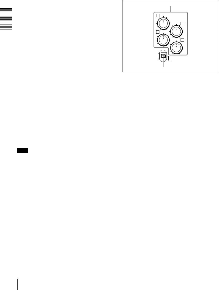
d SC control
e SYNC control
POWER
1
REC/PB
LEVEL 

 2
2
3 |
4
VAR
REC
PB |
PRESET |
SYNC
PHONES
SC
EJECT
h EJECT button
LOCAL
REMOTE
MENU RESET(NO)
dB OVER |
dB OVER |
INPUT |
AUDIO |
U-BIT SERVO |
CL |
REC INHI |
0 |
0 |
VIDEO |
|
|
|
V:SDTI COMPOSITE CH-1 1/2 CH-2 3/4 |
TC |
COUNTER |
NO EDIT |
REPEAT |
|
||||
-12 |
-12 |
SDTI |
S VIDEO |
ANALOG |
ANALOG |
|
|
|
TC |
|
|
-20 |
-20 |
i.LINK |
Y-R,B |
AES/EBU |
AES/EBU |
|
|
|
PRESET |
SET(YES) |
|
|
SDI |
SG |
SDI SG |
SDI SG |
|
|
|
||||
-30 |
-30 |
OUTPUT |
|
AUDIO |
|
|
|
|
|
||
-40 |
-40 |
|
VIDEO |
|
|
|
|
|
|||
-60 |
-60 |
SDI COMPOSITE |
CH 1/2 |
HOURS |
MINUTES |
SECONDS |
FRAMES |
|
SDTI |
S VIDEO |
CH 3/4 |
PB FS |
REC MODE |
VITC |
REMOTE |
||
CH- 1 |
3 CH- 2 4 |
|
Y-R,B |
|
48K 44.1K 32K |
2CH 4CH |
EDIT MODE |
9P i.LINK |
|
MONITOR |
METER |
|
INPUT SELECT |
|
|
COUNTER |
|
|
SELECT |
CH-1/2 3/4 |
SDTI/i.LINK |
VIDEO |
CH1 1/2 |
CH2 3/4 |
|
SELECT |
REW PLAY F FWD STOP REC
CONTROL S
|
|
|
|
|
|
|
j METER CH-1/2 3/4 |
|
|
l CONTROL S connector |
|
|
button |
|
|
||
|
|
|
|
|
|
|
|
|
|
|
|
|
|
|
|
||
|
|
|
|
k COUNTER SELECT button |
|
i MONITOR SELECT button |
|||||
|
|
|
|
|
|
AAudio input/output level control section (see page 14)
BVideo/audio input setting section (see page 15)
CDisplay section (see page 17)
POWER
1
REC/PB
LEVEL 

 2
2
3 |
4
VAR
REC
PB |
PRESET |
SYNC
PHONES
SC
EJECT
LOCAL
REMOTE
MENU RESET(NO)
dB OVER |
dB OVER |
INPUT |
AUDIO |
U-BIT SERVO |
CL |
REC INHI |
0 |
0 |
VIDEO |
|
|
|
V:SDTI COMPOSITE CH-1 1/2 CH-2 3/4 |
TC |
COUNTER |
NO EDIT |
REPEAT |
|
||||
-12 |
-12 |
SDTI |
S VIDEO |
ANALOG |
ANALOG |
|
|
|
TC |
|
|
|
|
i.LINK |
Y-R,B |
AES/EBU |
AES/EBU |
|
|
|
SET(YES) |
||
-20 |
-20 |
|
|
|
PRESET |
||||||
|
SDI |
SG |
SDI SG |
SDI SG |
|
|
|
||||
-30 |
-30 |
OUTPUT |
|
AUDIO |
|
|
|
|
|
||
-40 |
-40 |
|
VIDEO |
|
|
|
|
|
|||
-60 |
-60 |
SDI COMPOSITE |
CH 1/2 |
HOURS |
MINUTES |
SECONDS |
FRAMES |
||
SDTI |
S VIDEO |
CH 3/4 |
PB FS |
REC MODE |
VITC |
REMOTE |
|||
CH- 1 |
3 CH- 2 4 |
||||||||
|
Y-R,B |
|
48K 44.1K 32K |
2CH 4CH |
EDIT MODE |
9P i.LINK |
|||
|
MONITOR |
METER |
|
INPUT SELECT |
|
|
COUNTER |
||
|
SELECT |
CH-1/2 3/4 |
SDTI/i.LINK |
VIDEO |
CH1 1/2 |
CH2 3/4 |
|
SELECT |
|
REW PLAY F FWD STOP REC
CONTROL S
EMenu control section
(see page 21)
DTape transport control section (see page 20)
12 Location and Function of Parts

a POWER switch
Press the “ ” side to power on the unit. This causes the audio level meters and the display section to light. To power off the unit, press the “  ” side of the switch.
b Audio level meters
These two meters indicate the recording audio levels during recording or EE mode* and the playback audio levels during playback. When the audio level indicated on a meter exceeds 0 dB, the OVER indicator for the meter lights.
The short bars to the right of level indication bars indicate that those levels are reference audio recording levels. The settings made with the METER CH-1/2 3/4 button and MONITOR SELECT button select the audio channels for level indications on these meters as follows.
When CH-1/2 mode is selected with the METER CH-1/ 2 3/4 button:
Every time the MONITOR SELECT button is pressed, the audio channel selection for level indications on the two meters cycles through the following options.
•CH-1 (channel 1) only
Only the CH-1 indicator lights.
•CH-2 (channel 2) only
Only the CH-2 indicator lights.
•CH-1 and CH-2 (channels 1 and 2)
Both the CH-1 and CH-2 indicators light.
When CH-3/4 mode is selected with the METER CH-1/ 2 3/4 button:
Every time the MONITOR SELECT button is pressed, the audio channel selection for level indications on the two meters cycles through the following options.
•CH-3 (channel 3) only
Only the CH-3 indicator lights.
•CH-4 (channel 4) only
Only the CH-4 indicator lights.
•CH-3 and CH-4 (channels 3 and 4)
Both the CH-3 and CH-4 indicators light.
*E-E mode: Abbreviation of “Electric-to-Electric mode.” In this mode, video and audio signals input to the VCR are output after passing through internal electric circuits, but not through magnetic conversion circuits such as heads and tapes. This can be used to check input signals and for adjusting input signal levels.
c PHONES connector (stereo phone jack) and control knob
Connect stereo headphones to the connector for audio monitoring during recording or playback. The control knob controls the volume of the headphones. It also controls the level of the audio signal output from the MONITOR connector on the rear panel.
The settings made with the METER CH-1/2 3/4 button and MONITOR SELECT button select the audio channels for audio output via this connector. The same channel selection as for the audio level meters applies to this connector.
d SC (subcarrier phase) control
Turn this control to accurately adjust the subcarrier phase of the composite video output signal of the unit with respect to the reference video signal. Use a cross-point (Phillips) screwdriver to turn it.
e SYNC (synchronization phase) control
Turn this control to accurately adjust the synchronization phase of the output video signal of the unit with respect to the reference video signal. Use a cross-point (Phillips) screwdriver to turn it.
f Cassette compartment
Accepts DVCAM, DV and DVCPRO (25 Mbps) videocassettes.
For details of usable cassettes, see page 27.
g LOCAL/REMOTE switch
Selects whether the unit is operated from its front panel or from external equipment.
REMOTE: The unit is operated from external equipment connected to the REMOTE connector or i.DV IN/ OUT connector on the rear panel.
LOCAL: The unit is operated from its front panel or from a SIRCS-compatible remote control unit connected to the CONTROL S connector on the front panel.
h EJECT button
When you press this button, the cassette is automatically ejected after a few seconds.
i MONITOR SELECT button
Use this button and the METER CH-1/2 3/4 button to select the audio channels:
•for level indications on the audio level meters
•for audio output via the PHONES connector on the front panel
•for audio output via the MONITOR connector on the rear panel
Depending on the setting made with the METER CH-1/2 3/4 button, the channels for output to the above meters and connectors are selected as follows.
When CH-1/2 mode is selected with the METER CH-1/ 2 3/4 button:
Audio level meters |
PHONES |
MONITOR |
|
connector |
connector |
|
|
|
CH-1 (channel 1) only. |
Channel 1 only |
Channel 1 only |
Only the left meter lights. |
(monaural) |
|
|
|
|
CH-2 (channel 2) only. |
Channel 2 only |
Channel 2 only |
Only the right meter |
(monaural) |
|
lights. |
|
|
|
|
|
CH-1 and CH-2 (channels |
Channels 1 |
Channels 1 |
1 and 2). |
and 2 (stereo) |
and 2 (mixed) |
Both the left and right |
|
|
meters light. |
|
|
|
|
|
Overview 1 Chapter
Location and Function of Parts |
13 |
|
|
Overview 1 Chapter
When CH-3/4 mode is selected with the METER CH-1/ 2 3/4 button:
Audio level meters |
PHONES |
MONITOR |
|
connector |
connector |
|
|
|
CH-3 (channel 3) only. |
Channel 3 only |
Channel 3 only |
Only the left meter lights. |
(monaural) |
|
|
|
|
CH-4 (channel 4) only. |
Channel 4 only |
Channel 4 only |
Only the right meter |
(monaural) |
|
lights. |
|
|
|
|
|
CH-3 and CH-4 (channels |
Channels 3 |
Channels 3 |
3 and 4). |
and 4 (stereo) |
and 4 (mixed) |
Both the left and right |
|
|
meters light. |
|
|
|
|
|
j METER CH-1/2 3/4 button
Pressing this button toggles the audio level meter mode between CH-1/2 (channels 1 and 2) and CH-3/4 (channels 3 and 4).
The settings made with this button and the MONITOR SELECT button select the channels for level indications and audio output.
For more details, see “iMONITOR SELECT button.”
k COUNTER SELECT button
Selects the type of time data to be shown in the time counter display. Each press of this button cycles through the following three indicator display options:
•COUNTER (CNT: count value of the time counter)
•TC (time code)
•U-BIT (user bits)
Note
If the LOCAL/REMOTE switch is set to REMOTE, the COUNTER SELECT button does not operate while the tape is moving. In this case, make the time data selection via the external equipment connected to the REMOTE connector on the rear panel.
l CONTROL S connector (stereo minijack)
Connect a SIRCS-compatible remote control unit such as the DSRM-10 to this connector.
AAudio input/output level control section
|
a REC/PB LEVEL control knobs |
1 |
REC/PB |
|
|
|
LEVEL |
|
2 |
3 |
|
|
4 |
VAR |
|
REC |
|
PB |
PRESET |
|
|
|
b VAR switch |
a REC/PB LEVEL control knobs
These knobs used to control audio levels function differently depending on the setting of the VAR switch as follows.
VAR switch |
Functions of control knobs |
setting |
|
|
|
PRESET |
Control knobs are not effective. |
|
The analog audio input/output levels are set to |
|
the reference level set with the LEVEL |
|
SELECT menu item (see page 72). |
|
|
REC |
Control the analog/digital audio input levels on |
|
channels 1 to 4 during recording. |
|
|
PB |
Control the analog/digital audio output levels |
|
on channels 1 to 4 during playback. |
|
|
b VAR switch
Use to switch the way in which the REC/PB LEVEL control knobs function.
14 Location and Function of Parts
BVideo/audio input setting section
|
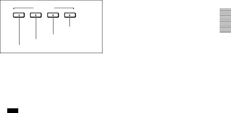
INPUT SELECT |
|
|
SDTI/i.LINK |
VIDEO |
CH1 1/2 |
CH2 3/4 |
d CH2 3/4 button
c CH1 1/2 button b VIDEO button
a SDTI/i.LINK button
a SDTI/i.LINK (SDTI (QSDI) interface/i.LINK selection) button
Each press of this button cycles through the following input signal selection options.
•Digital video signal in SDTI (QSDI) format input to the SDI/SDTI (QSDI) IN connector (optional DSBK-1501 board required)
When this is selected, use the CH1 1/2 button and CH2 3/4 button to select the required input audio signals.
Note
In this case, the phases of the selected audio signals will be about two frames ahead of the phase of the digital video signal in SDTI (QSDI) format.
•Digital video and audio signals in SDTI (QSDI) format input to the SDI/SDTI (QSDI) IN connector (optional DSBK-1501 board required)
•Digital video and audio signals in i.LINK-compatible DV format input to the i.DV IN/OUT connector
The selection made with this button is indicated in the INPUT signal display section (see page 18).
b VIDEO button
Each press of this button cycles through the following input video signal selection options.
• Composite video signal input to the VIDEO IN connector (optional DSBK-1504/1504P board required)
•S-video (separated Y and C) signals input to the VIDEO IN connectors (optional DSBK-1504/1504P board required)
•Y, R−Y and B−Y component video signals input to the VIDEO IN connectors (optional DSBK-1504/1504P board required)
•SDI video signal input to the SDI/SDTI (QSDI) IN connector (optional DSBK-1501 board required)
•Video test signal (selected with the INT VIDEO SG
menu item (see page 70)) generated by the internal signal generator
The selection made with this button is indicated by the VIDEO indicators in the INPUT signal display section (see page 17).
c CH1 1/2 (audio channel 1 or 1/2) button
Each press of this button cycles through the following input audio signal selection options for audio channel 1 (when in 2-channel mode) or for audio channels 1 and 2 (when in 4-channel mode).
•Analog audio signal input to the AUDIO IN 1/3 connector (optional DSBK-1504/1504P board required)
•Digital audio signal in AES/EBU format input to the AUDIO (AES/EBU) IN 1/2 connector (optional DSBK1501 board required)
•SDI audio signal input to the SDI/SDTI (QSDI) IN connector (optional DSBK-1501 board required)
•Audio test signal (selected with the INT AUDIO SG menu item (see page 72) generated by the internal signal generator
The selection made with this button is indicated by the AUDIO CH-1 1/2 indicators in the INPUT signal display section (see page 17).
When analog audio is selected (optional DSBK-1504/ 1504P board required), the signal input to the AUDIO IN 1/3 connector is recorded either on channel 1 (when in 2- channel mode) or on channels 1 and 3 (when in 4-channel mode). That is, in 4-channel mode, the same analog audio signal is recorded on channels 1 and 3. Using the REC/PB LEVEL control knobs with the VAR switch set to REC, it is possible to adjust the audio levels on the two channels separately.
You can switch the audio recording mode with the REC MODE menu item (see page 71). The selection is indicated by the REC MODE display on the front panel.
d CH2 3/4 (audio channel 2 or 3/4) button
Each press of this button cycles through the following input audio signal selection options for audio channel 2 (when in 2-channel mode) or for audio channels 3 and 4 (when in 4-channel mode).
•Analog audio signal input to the AUDIO IN 2/4 connector (optional DSBK-1504/1504P board required)
•Digital audio signal in AES/EBU format input to the AUDIO (AES/EBU) IN 3/4 connector (optional DSBK1501 board required)
•SDI audio signal input to the SDI/SDTI (QSDI) IN connector (optional DSBK-1501 board required)
•Audio test signal (selected with the INT AUDIO SG menu item (see page 72) generated by the internal signal
generator
The selection made with this button is indicated by the AUDIO CH-2 3/4 indicators in the INPUT signal display section (see page 17).
When analog audio is selected (optional DSBK-1504/ 1504P board required), the signal input to the AUDIO IN 2/4 connector is recorded either on channel 2 (when in 2- channel mode) or on channels 2 and 4 (when in 4-channel mode). That is, in 4-channel mode, the same analog audio signal is recorded on channels 2 and 4. Using the REC/PB LEVEL control knobs with the VAR switch set to REC, it
Overview 1 Chapter
Location and Function of Parts |
15 |
|
|

is possible to adjust the audio levels on the two channels separately.
You can switch the audio recording mode with the REC MODE menu item (see page 71). The selection is indicated by the REC MODE display on the front panel.
Overview 1 Chapter
16 Location and Function of Parts
CDisplay section
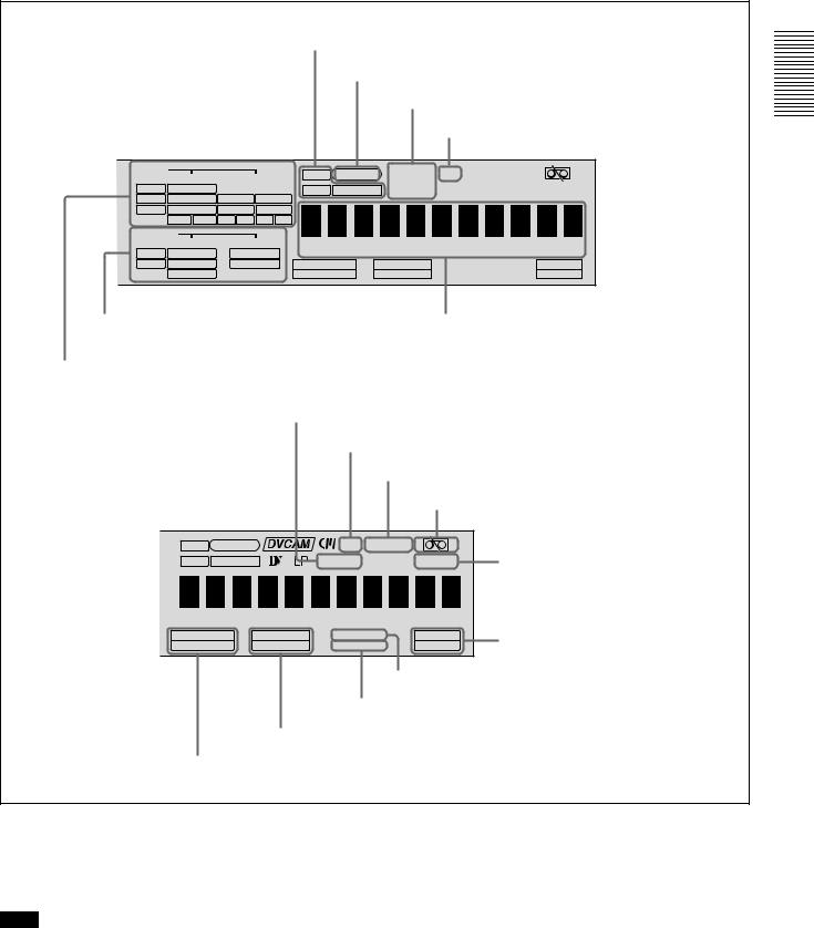
d Time data type indicators
e SERVO indicator
f Recording/playback tape format indicators
g Cassette memory indicator
INPUT |
VIDEO |
AUDIO |
|
|
|||
V:SDTI COMPOSITE CH-1 1/2 CH-2 3/4 |
|||
SDTI |
S VIDEO |
ANALOG |
ANALOG |
i.LINK |
Y-R,B |
AES/EBU |
AES/EBU |
|
SDI SG |
SDI SG |
SDI SG |
OUTPUT |
AUDIO |
||
|
VIDEO |
||
SDI |
COMPOSITE |
CH 1/2 |
|
SDTI |
S VIDEO |
CH 3/4 |
|
|
Y-R,B |
|
|
U-BIT SERVO 

 CL REC INHI
TC COUNTER 
 NO EDIT REPEAT
HOURS |
MINUTES |
SECONDS |
FRAMES |
PB FS |
REC MODE |
VITC |
REMOTE |
48K 44.1K 32K |
2CH 4CH |
EDIT MODE |
9P i.LINK |
b OUTPUT signal display section |
c Time counter display |
a INPUT signal display section
hNO EDIT indicator
i CL indicator
j REC INHI indicator
k Tape end alarm indicator
U-BIT |
SERVO |
|
CL REC INHI |
|
TC |
COUNTER |
|
NO EDIT |
REPEAT |
HOURS |
MINUTES |
SECONDS |
FRAMES |
|
PB FS |
REC MODE |
VITC |
REMOTE |
|
48K 44.1K 32K |
2CH 4CH |
EDIT MODE |
9P i.LINK |
|
q VITC indicator
p EDIT MODE indicator
o REC MODE display
n PB Fs display
l REPEAT indicator
m Remote mode indicators
Overview 1 Chapter
a INPUT signal display section
Indicates the input video and audio signal formats selected with the INPUT SELECT buttons (SDTI/i.LINK, VIDEO, CH1 1/2, and CH2 3/4 buttons).
Note
The indicators without the corresponding optional boards installed in the unit do not light.
V:SDTI indicator: Lights when the digital video signal only in SDTI (QSDI) format is selected (optional DSBK-1501 board required).
SDTI indicator: Lights when the digital video and audio signals in SDTI (QSDI) format are selected (optional DSBK-1501 board required).
i.LINKindicator: Lights when the digital video and audio signals in i.LINK-compatible DV format are selected.
Location and Function of Parts |
17 |
|
|

Overview 1 Chapter
VIDEO indicators: The indicator (COMPOSITE, S VIDEO, Y−R,B, SDI, or SG) corresponding to the selected input video signal format lights.
Indicators |
Meanings |
|
|
COMPOSITE |
Composite video signal (optional |
|
DSBK-1504/1504P board required) |
|
|
S VIDEO |
S-video (separated Y and C) signals |
|
(optional DSBK-1504/1504P board |
|
required) |
|
|
Y−R,B |
Y, R−Y and B−Y component video |
|
signals (optional DSBK-1504/1504P |
|
board required) |
|
|
SDI |
SDI video signal (optional DSBK-1501 |
|
board required) |
|
|
SG |
Video test signal (factory default |
|
setting) |
|
|
AUDIO indicators: Comprise the CH-1 1/2 indicator and CH-2 3/4 indicator, under each of which there are four more indicators (ANALOG, AES/EBU, SDI, and SG). They indicate the selected input audio signal formats.
Indicators |
Functions |
|
|
CH-1 1/2 |
The indicator corresponding to the |
(ANALOG, AES/ |
signal format selected for audio input |
EBU, SDI, SG) |
to channel 1 (when in 2-channel |
|
mode) or to channels 1 and 2 (when |
|
in 4-channel mode) lights. |
|
ANALOG: Analog audio signal |
|
(optional DSBK-1504/1504P |
|
board required) |
|
AES/EBU: Digital audio signal in |
|
AES/EBU format (optional |
|
DSBK-1501 board required) |
|
SDI: SDI audio signal (optional |
|
DSBK-1501 board required) |
|
SG: Audio test signal (factory default |
|
setting) |
|
|
CH-2 3/4 |
The indicator corresponding to the |
(ANALOG, AES/ |
signal format selected for audio input |
EBU, SDI, SG) |
to channel 2 (when in 2-channel |
|
mode) or to channels 3 and 4 (when |
|
in 4-channel mode) lights. |
|
ANALOG: Analog audio signal |
|
(optional DSBK-1504/1504P |
|
board required) |
|
AES/EBU: Digital audio signal in |
|
AES/EBU format (optional |
|
DSBK-1501 board required) |
|
SDI: SDI audio signal (optional |
|
DSBK-1501 board required) |
|
SG: Audio test signal (factory default |
|
setting) |
|
|
b OUTPUT signal display section
Indicates the output video and audio signal format selected with the INTERFACE SELECT menu items (see page 73).
Note
The indicators without the corresponding optional boards installed in the unit do not light.
SDI indicator: Lights when the digital video and audio signals in SDI format are selected (optional DSBK1501 board required).
The SDI video and audio signals are output to the SDI/ SDTI (QSDI) OUT1 and OUT2 connectors.
SDTI indicator: Lights when the digital video and audio signals in SDTI (QSDI) format are selected (optional DSBK-1501 board required).
The video and audio signals in SDTI (QSDI) format are output to the SDI/SDTI (QSDI) OUT1 and OUT2 connectors.
VIDEO indicators: The indicator (COMPOSITE, S VIDEO, or Y−R,B) corresponding to the selected output analog video signal format lights.
Indicators |
Meanings |
|
|
COMPOSITE |
Composite video signal |
|
|
S VIDEO |
S-video (separated Y and C) signals |
|
|
Y−R,B |
Y, R−Y and B−Y component video |
|
signals |
|
|
This selection determines the signals output from the Y/CPST, R−Y/C/CPST, and B−Y/CPST (SUPER) connectors as follows.
• When COMPOSITE is selected:
|
Connectors |
Output signals |
|
|
|
|
Y/CPST |
Composite signal |
|
|
|
|
R−Y/C/CPST |
Composite signal |
|
|
|
|
B−Y/CPST (SUPER) |
Composite signal |
|
|
|
• |
When S VIDEO is selected: |
|
|
|
|
|
Connectors |
Output signals |
|
|
|
|
Y/CPST |
Y signal |
|
|
|
|
R−Y/C/CPST |
C signal |
|
|
(3.58 MHz for DSR-1500A/ |
|
|
4.43 MHz for DSR-1500AP) |
|
|
|
|
B−Y/CPST (SUPER) |
Composite signal |
|
|
|
• |
When Y–R,B is selected: |
|
|
|
|
|
Connectors |
Output signals |
|
|
|
|
Y/CPST |
Y signal |
|
|
|
|
R−Y/C/CPST |
R−Y signal |
|
|
|
|
B−Y/CPST (SUPER) |
B−Y signal |
|
|
|
18 Location and Function of Parts

AUDIO indicators: Comprise the CH 1/2 indicator and CH 3/4 indicator to indicate the channel selection for analog audio output from the AUDIO OUT 1/3 and AUDIO OUT 2/4 connectors.
Indicators |
Functions |
|
|
CH 1/2 |
Lights when channels 1 and 2 are |
|
selected for analog audio output from |
|
the AUDIO OUT 1/3 and AUDIO OUT |
|
2/4 connectors. |
|
|
CH 3/4 |
Lights when channels 3 and 4 are |
|
selected for analog audio output from |
|
the AUDIO OUT 1/3 and AUDIO OUT |
|
2/4 connectors. |
|
|
You can change the channel selection with the AUDIO OUTPUT menu item (see page 73).
c Time counter display
Indicates the count value of the time counter, time code, VITC, or user bit data depending on the settings of the COUNTER SELECT button and the TC SELECT menu item (see page 68).
Also used to display error messages, edit data, setup menu data, etc.
d Time data type indicators
One of the three indicators (COUNTER, U-BIT, or TC) lights to indicate the type of time data currently shown in the time counter display.
COUNTER: Count value of the time counter U-BIT: User bit data
TC: SMPTE time code (for DSR-1500A) or EBU time code (for DSR-1500AP)
e SERVO (servolock) indicator
Lights when the drum servo and capstan servo are locked.*
*Servolock: Synchronizing the drum rotation phase and tape transport phase with a reference signal during playback and recording so that the video heads scan the tape in the same pattern during playback and recording.
f Recording/playback tape format indicators DVCAM: This lights when recording or playback is
carried out in DVCAM format.
DV: This lights when recording or playback is carried out in consumer DV format.
LP: This flashes along with “DV” when a tape recorded in LP mode is played back.
Video recorded in LP mode cannot be played back correctly and audio is muted.
When a tape recorded in DVCPRO (25 Mbps) format or any other format than those mentioned above is played back, none of the above indicators lights.
The recording format can be changed with the REC FORMAT menu item (see page 65). The factory default setting of the recording format is DVCAM.
g Cassette memory indicator
Lights when a cassette provided with a memory chip (“cassette memory”) is loaded.
h NO EDIT (not editable) indicator
When the recording format setting is DVCAM
Lights during playback of a tape that contains a recording in other than the DVCAM format. When this indicator is lit, the recordings contained in the tape can be used as source material for editing, but editing operations such as insert editing and assemble editing cannot be performed. This indicator also lights when the audio recording mode selected on this unit does not coincide with that of the loaded tape during editing operation.
When the recording format setting is DV (SP)
Lights during playback of a tape that contains a recording in DVCAM, DV, or DVCPRO format.
i CL (ClipLink) indicator
Lights when a cassette is loaded on which ClipLink log data is stored in the cassette memory.
For details of ClipLink log data, see the appendix “ClipLink Guide” (page 113).
j REC INHI (recording inhibit) indicator
Lights when the REC/SAVE switch on the loaded cassette is in the SAVE position (recording inhibited).
k Tape end alarm indicator
Starts flashing when the remaining capacity of the tape is for about 2 minutes.
l REPEAT (repeat playback) indicator
Lights when the REPEAT MODE menu item (see page 64) is set to ON to enable the repeat playback function.
m Remote mode indicators
REMOTE: Lights when the LOCAL/REMOTE switch is set to REMOTE to remote control the unit from either an editing control unit connected to the REMOTE connector or equipment connected to the i.DV IN/ OUT connector.
9P: Lights when the REMOTE I/F menu item (see page 73) is set to 9PIN.
i.LINK: Lights when the REMOTE I/F menu item (see page 73) is set to i.LINK.
n PB Fs (playback audio sampling frequency) display
During playback, this indicates the playback audio mode in which the tape being played back was recorded.
48K indicator: Lights during playback of a tape recorded in 2-channel mode (48 kHz).
44.1K indicator: Lights during playback of a tape recorded in 2-channel mode (44.1 kHz).
Overview 1 Chapter
Location and Function of Parts |
19 |
|
|

Overview 1 Chapter
32K indicator: Lights during playback of a tape recorded in 4-channel mode (32 kHz).
o REC MODE (audio recording mode) display
This indicates the audio recording mode currently selected with the REC MODE menu item (see page 71).
2CH indicator: Lights in 2-channel mode (48 kHz). 4CH indicator: Lights in 4-channel mode (32 kHz).
DTape transport control section
p EDIT MODE indicator
Lights when this unit is selected as the recorder VCR under the control of either an editing control unit connected to the REMOTE connector or equipment connected to the i.DV IN/OUT connector.
q VITC indicator
Lights when VITC is being read or recorded regardless of the data shown in the time counter display.
REW |
PLAY |
F FWD |
STOP |
|
REC |
|
|
|
|
|
|
|
|
|
|
|
|
e REC button
d STOP button
c F FWD button
b PLAY button
a REW button
a REW (rewind) button
When you press this button, it lights and the tape starts rewinding.
When the F. FWD/REW menu item under the AUTO EE SELECT menu item (see page 65) is set to PB, the picture appears on the monitor during rewind (maximum 85 times normal speed).
b PLAY button
When you press this button, it lights and playback begins. If you press this button during recording or editing, the recording or editing operation is stopped and this unit enters playback mode.
c F FWD (fast forward) button
When you press this button, it lights and the tape is fast forwarded.
When the F. FWD/REW menu item under the AUTO EE SELECT menu item (see page 65) is set to PB, the picture appears on the monitor during fast forward (maximum 85 times normal speed).
d STOP button
Press this button to stop the current tape transport operation.
e REC (record) button
When you press this button while holding down the PLAY button, it lights and recording begins.
Note
When the LOCAL/REMOTE switch is set to REMOTE (the REMOTE indicator is lit), no tape transport control buttons other than the EJECT and STOP buttons will work. This can be changed with the LOCAL ENABLE menu item (see page 65).
20 Location and Function of Parts
EMenu control section
a MENU button
b RESET (NO) button
MENU RESET(NO)
c TC PRESET button
TC
PRESET SET(YES)
d SET (YES) button
e fFgG buttons
a MENU button
Press this button to display the menu on the monitor screen and the time counter display. Press it again to exit the menu display.
On how to use the menu, see Chapter 4 “Menu Settings.”
b RESET (NO) button
Press this button to:
•reset menu settings,
•reset the time data shown in the time counter display to zero, or
•send a negative response to the prompts issued by the unit.
c TC (time code) PRESET button
Use this button to set the initial value of the time code produced by the internal time code generator and user bit data.
For details on setting an initial time code value and user bit data, see “To set the initial time code value and user bit data” on page 51.
d SET (YES) button
Press this button to:
•save new settings, such as selected menu items and time code settings, to memory, or
•send a positive response to the prompts issued by the unit.
e fFgG (arrow) buttons
Use these buttons to move around the menu items, and also to modify the initial time code value and user bit data. When the SEARCH ENABLE menu item (see page 65) is set to ENABLE, you can also use these buttons to carry out the following playback operations.
Playback type |
Direction |
Operation to carry out |
|
|
|
|
|
Playback in range |
Forward |
Press the G button. |
|
±10 times normal |
|
|
|
Reverse |
Press the g button. |
||
speed |
|||
|
|
||
|
|
|
|
Frame-by-frame |
Forward |
Press the f button. |
|
playback |
|
|
|
Reverse |
Press the F button. |
||
|
|||
|
|
|
|
Continuous |
Forward |
Hold down the f button. |
|
playback in jog |
|
|
|
Reverse |
Hold down the F button. |
||
mode |
|||
|
|
||
|
|
|
For details on modifying the time code value, see “To set the initial time code value and user bit data” on page 51.
Overview 1 Chapter
Location and Function of Parts |
21 |
|
|
Rear Panel
Overview 1 Chapter
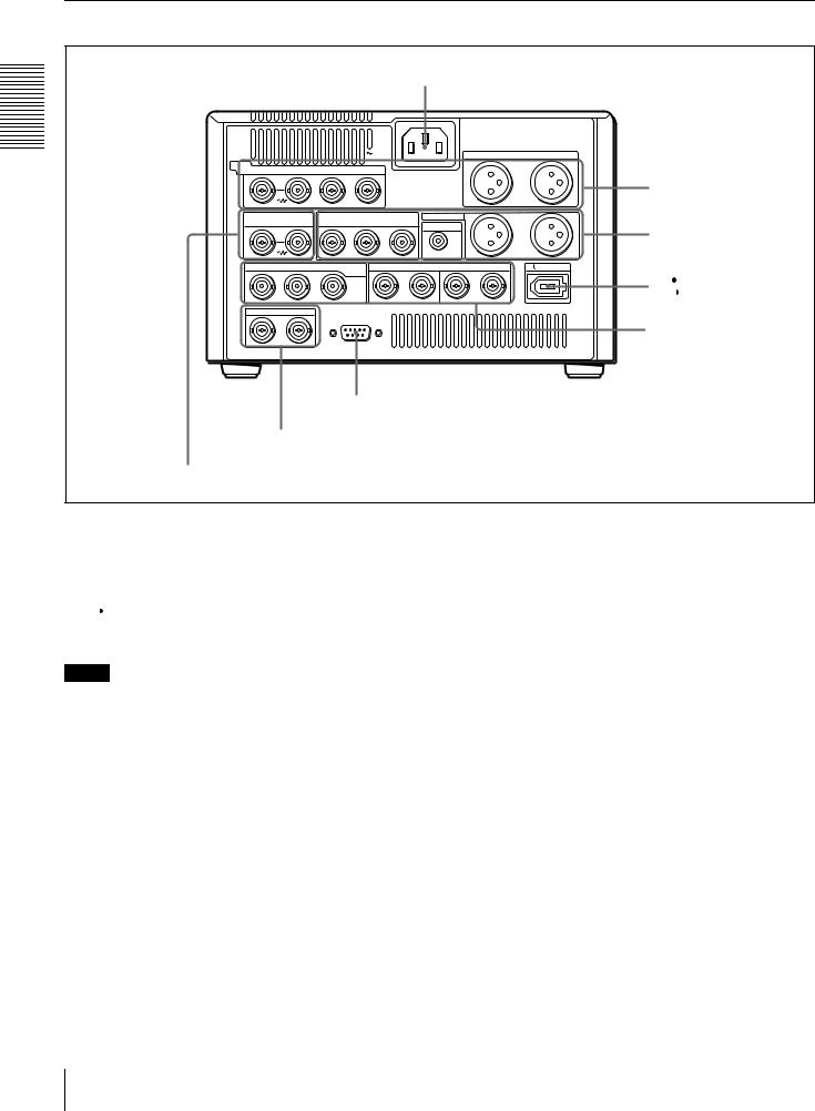
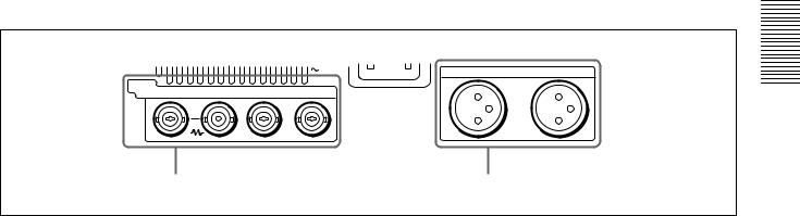
a AC IN connector
|
|
|
AC IN |
|
|
|
|
AUDIO IN |
|
|
VIDEO |
|
R-Y/C |
B-Y |
|
|
|
|
1/3 |
|
2/4 |
IN Y/CPST |
|
|
|
|
|
|
|
|
||
REF.VIDEO |
Y/CPST |
VIDEO OUT |
(SUPER) |
|
AUDIO OUT |
1/3 |
|
2/4 |
||
IN |
|
R-Y/C/CPST B-Y/CPST |
MONITOR |
|
|
|
||||
|
|
|
|
|
|
|
|
|
||
IN |
OUT1 |
OUT2 SDI/SDTI |
IN |
AUDIO I/O (AES/EBU) |
OUT |
DV IN/OUT |
||||
|
|
|
(QSDI) |
|
|
|
|
|
|
|
|
|
|
1/2 |
|
|
3/4 |
1/2 |
|
|
3/4 |
TC IN |
OUT |
|
|
|
|
|
|
|
|
|
|
|
|
REMOTE |
|
|
|
|
|
|
|
c REMOTE connector
DTime code input/output section (see page 25)
d REF. VIDEO IN connectors
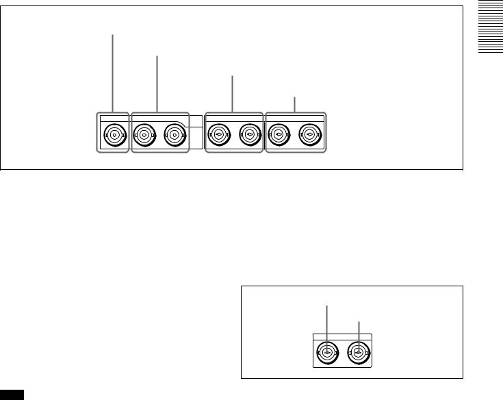
AAnalog video/audio signal input section
(see page 23)
BAnalog video/audio signal output section
(see page 24)
b  DV IN/OUT connector
CDigital signal input/output section (see page 25)
a AC IN connector
Use the supplied power cord to connect this to an AC outlet.
b  DV IN/OUT connector (6-pin IEEE-1394)
This connector inputs and outputs digital video and audio signals in DV format.
Notes
•If the unit is connected to a device equipped with a 6-pin DV jack, when you intend to disconnect or reconnect the DV cable, turn off the device and pull out the plug of its power cord from the AC outlet beforehand. If you connect or disconnect the DV cable while the device is connected to the AC outlet, high-voltage current (8 to 40 V) is output from the DV jack of the device to this unit, which may cause a malfunction.
•When connecting a device that has a 6-pin DV jack to this unit, first connect the plug of the cable to the 6-pin DV jack of the device.
•When searching at speeds in the range +1/2 to +1/30 or −1/30 to −1/2 times normal speed, the audio signal output from this connector and monitored on external equipment may sound differently from the audio signal played back on this unit.
c REMOTE connector (D-sub 9-pin)
When controlling this unit from an editing control unit such as the ES-7, PVE-500, BVE-600/800/910, or RM450/450CE, connect the editing control unit to this connector using the optional 9-pin remote control cable.
dREF. (reference) VIDEO IN connectors (BNC type)
Input a reference video signal. The two connectors are loop-through connectors. You can connect the reference video signal input to the left connector to other equipment via the right connector (marked  ). When no connection is made to the right connector, the left connector is terminated with an impedance of 75 Ω automatically.
22 Location and Function of Parts
AAnalog video/audio signal input section (optional DSBK-1504/1504P Analog Input
Board)
The connectors in this section are available when the optional DSBK-1504/1504P board is installed.
|
|
AC IN |
AUDIO IN |
|
VIDEO |
R-Y/C |
B-Y |
1/3 |
2/4 |
IN Y/CPST |
|
|
a VIDEO IN connectors |
b AUDIO IN 1/3 and AUDIO IN 2/4 connectors |
a VIDEO IN connectors (BNC type)
There are the following VIDEO IN connectors for inputting analog video signals:
•Y/CPST (loop-through connectors)
•R−Y/C
•B−Y
The signals you can connect to these connectors depend on the selection made with the VIDEO button in the video/ audio input selection section. The selection is indicated by the VIDEO indicators in the INPUT signal display section. The analog video signals that can be input to these connectors are as follows.
When COMPOSITE is selected:
Connectors |
Input signals |
|
|
Y/CPST |
Composite signal |
|
|
R−Y/C |
— (not usable) |
|
|
B−Y |
— (not usable) |
|
|
The two Y/CPST connectors are loop-through connectors. When using the signal input to the left Y/ CPST connector as a reference video signal, for example, you can bridge-connect the signal to other equipment via the right Y/CPST connector (marked  ). When no connection is made to the right Y/ CPST connector, the left Y/CPST connector is terminated with an impedance of 75 Ω automatically.
When S VIDEO is selected:
Connectors |
Input signals |
|
|
Y/CPST |
Y signal |
|
|
R−Y/C |
C signal |
|
(3.58 MHz for DSR-1500A/ |
|
4.43 MHz for DSR-1500AP) |
|
|
B−Y |
— (not usable) |
|
|
When Y–R,B is selected:
Connectors |
Input signals |
|
|
Y/CPST |
Y signal |
|
|
R−Y/C |
R−Y signal |
|
|
B−Y |
B−Y signal |
|
|
bAUDIO IN 1/3 and AUDIO IN 2/4 connectors (XLR-3 pin, female)
Use these connectors to input analog audio signals from an external video cassette player or other audio equipment. The signals input to these connectors are recorded on the audio channels determined by the current audio recording mode, as follows.
When in 2 CH (48 kHz) mode:
Input |
Audio channels on which input |
connectors |
signals are recorded |
|
|
AUDIO IN 1/3 |
Audio channel 1 |
|
|
AUDIO IN 2/4 |
Audio channel 2 |
|
|
When in 4 CH (32 kHz) mode:
Input |
Audio channels on which input |
connectors |
signals are recorded |
|
|
AUDIO IN 1/3 |
Audio channels 1 and 3 |
|
|
AUDIO IN 2/4 |
Audio channels 2 and 4 |
|
|
You can switch the audio recording mode with the REC MODE menu item (see page 71). The selection is indicated by the REC MODE display on the front panel.
Overview 1 Chapter
Location and Function of Parts |
23 |
|
|

Overview 1 Chapter
BAnalog video/audio signal output section
a VIDEO OUT connectors
b AUDIO OUT 1/3 and AUDIO OUT 2/4 connectors
VIDEO OUT |
(SUPER) |
AUDIO OUT 1/3 |
2/4 |
Y/CPST R-Y/C/CPST |
B-Y/CPST |
MONITOR |
|
|
|
|
c MONITOR connector
a VIDEO OUT connectors (BNC type)
There are the following VIDEO OUT connectors for outputting analog video signals:
•Y/CPST
•R−Y/C/CPST
•B−Y/CPST (SUPER)
The signals output from these connectors depend on the setting of the VIDEO OUTPUT menu item (see page 73). The setting is indicated by the VIDEO indicators in the OUTPUT signal display section on the front panel.
The analog video signals that can be output from these connectors are as follows.
When COMPOSITE is selected:
Connectors |
Output signals |
|
|
Y/CPST |
Composite signal |
|
|
R−Y/C/CPST |
Composite signal |
|
|
B−Y/CPST |
Composite signal |
(SUPER) |
|
|
|
When the CHARA. DISPLAY menu item (see page 66) is set to ON (factory default setting), the B−Y/ CPST (SUPER) connector outputs a composite video signal with superimposed text information.
When S-VIDEO is selected:
Connectors |
Output signals |
|
|
Y/CPST |
Y signal |
|
|
R−Y/C/CPST |
C signal |
|
(3.58 MHz for DSR-1500A/ |
|
4.43 MHz for DSR-1500AP) |
|
|
B−Y/CPST |
Composite signal |
(SUPER) |
|
|
|
When the CHARA. DISPLAY menu item (see page 66) is set to ON (factory default setting), the B−Y/ CPST (SUPER) connector outputs a composite video signal with superimposed text information.
When Y–R, B is selected:
Connectors |
Output signals |
|
|
Y/CPST |
Y signal |
|
|
R−Y/C/CPST |
R−Y signal |
|
|
B−Y/CPST |
B−Y signal |
(SUPER) |
|
|
|
bAUDIO OUT 1/3 and AUDIO OUT 2/4 connectors (XLR-3 pin, male)
These connectors output analog audio signals. The output audio channels are determined by the playback audio mode and the setting (1/2 CH or 3/4 CH) of the AUDIO OUTPUT menu item (see page 73) as follows.
When in 2 CH (48 kHz or 44.1 kHz) mode:
Output |
Output audio channels |
connectors |
|
|
|
AUDIO OUT 1/3 |
Audio channel 1 (when 1/2 CH is |
|
selected) or silent (when 3/4 CH is |
|
selected) |
|
|
AUDIO OUT 2/4 |
Audio channel 2 (when 1/2 CH is |
|
selected) or silent (when 3/4 CH is |
|
selected) |
|
|
When in 4 CH (32 kHz) mode:
Output |
Output audio channels |
connectors |
|
|
|
AUDIO OUT 1/3 |
Audio channel 1 (when 1/2 CH is |
|
selected) or audio channel 3 (when 3/ |
|
4 CH is selected) |
|
|
AUDIO OUT 2/4 |
Audio channel 2 (when 1/2 CH is |
|
selected) or audio channel 4 (when 3/ |
|
4 CH is selected) |
|
|
The current playback audio mode is indicated by the PB Fs display on the front panel.
c MONITOR connector (RCA phono jack)
This connector outputs audio signals for monitoring. The audio signals to be output from this connector can be selected with the MONITOR SELECT button and METER CH-1/2 3/4 button on the front panel.
24 Location and Function of Parts
CDigital signal input/output section (optional DSBK-1501 Digital Input/Output Board)
The connectors in this section are available when the optional DSBK-1501 board is installed.
a SDI/SDTI (QSDI) IN connector
b SDI/SDTI (QSDI) OUT1/OUT2 connectors
c AUDIO (AES/EBU) IN 1/2 and AUDIO (AES/EBU) IN 3/4 connectors
d AUDIO (AES/EBU) OUT 1/2 and AUDIO (AES/EBU) OUT 3/4 connectors
IN |
OUT1 |
OUT2 SDI/SDTI |
IN |
AUDIO I/O (AES/EBU) |
OUT |
|
|
|
(QSDI) |
|
|
|
|
|
|
1/2 |
|
3/4 |
1/2 |
3/4 |
aSDI/SDTI (QSDI) IN (Serial Digital Interface/ Serial Data Transport Interface (QSDI) input)
connector (BNC type)
This connector inputs digital video and audio signals in SDTI (QSDI) or SDI format. To select the required input signal formats, use the SDTI/i.LINK button or VIDEO button on the front panel. The current input signal selections are indicated in the INPUT signal display section on the front panel.
bSDI/SDTI (QSDI) OUT1/OUT2 (Serial Digital Interface/Serial Data Transport Interface (QSDI)
output 1/output 2) connectors (BNC type)
These connectors output digital video and audio signals in SDTI (QSDI) or SDI format. To select these output signal formats, use the DIGITAL OUTPUT menu item (see page 73). The current output signal selections are indicated in the OUTPUT signal display section on the front panel.
Note
When searching at speeds in the range +1/2 to +1/30 or −1/2 to −1/30 times normal speed, the audio signal output from these connectors in SDTI (QSDI) format and monitored on external equipment may sound differently from the audio signal played back on this unit.
cAUDIO (AES/EBU) IN 1/2 and AUDIO (AES/ EBU) IN 3/4 connectors (BNC type)
Input digital audio signals in AES/EBU format to these connectors.
The left connector (1/2) is for audio channels 1 and 2, and the right connector (3/4) is for audio channels 3 and 4.
dAUDIO (AES/EBU) OUT 1/2 and AUDIO (AES/ EBU) OUT 3/4 connectors (BNC type)
These connectors output digital audio signals in AES/EBU format.
The left connector (1/2) is for audio channels 1 and 2, and the right connector (3/4) is for audio channels 3 and 4.
DTime code input/output section
a TC IN connector
b TC OUT connector
TC IN |
OUT |
a TC IN (time code input) connector (BNC type)
Input externally generated SMPTE time code (for DSR1500A) or EBU time code (for DSR-1500AP) to this connector.
b TC OUT (time code output) connector (BNC type)
This connector outputs a time code according to the operating state of the unit, as follows:
During playback: the playback time code
During recording: the time code generated by the internal time code generator or the time code input to the TC IN connector. When the EE OUT PHASE menu item (see page 69) is set to MUTE, no time code is output.
Overview 1 Chapter
Location and Function of Parts |
25 |
|
|

Overview 1 Chapter
26 Location and Function of Parts

Recording and Playback Chapter 2
Usable Cassettes
This unit can use the DVCAM cassettes listed below.
Model name |
Size |
|
|
PDV-64ME/94ME/124ME/184ME |
Standard size |
|
|
PDVM-12ME/22ME/32ME/40ME |
Mini size |
|
|
The numbers in each model name indicate the maximum recording/playback time (in minutes) for each model. For example, the PDV-184ME has a maximum recording/playback time of 184 minutes.
Cassettes usable for playback only
All consumer DV cassettes and largeand medium-size DVCPRO (25 Mbps) cassettes are usable for playback only.
Notes
•If you insert an incorrect type of cassette, it will be automatically ejected.
•When operating this unit as a player, you can also use DV cassettes on the unit. However, it is the best choice to always use DVCAM cassettes because they are more reliable than DV cassettes whatever your purpose may be: playback, editing, or long-period storage of recordings.
•Cassettes that have been recorded by a DV-format recorder can be played back on this unit but cannot be used for recording at editing operation. When you insert such a cassette into this unit, the NO EDIT indicator lights up in the display section on the front panel of this unit.
Usable Cassettes 27
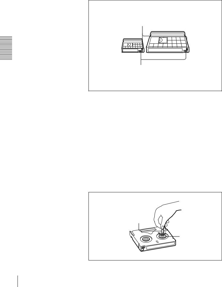
DVCAM cassettes
The following figure illustrates the DVCAM cassettes.
Playback and Recording 2 Chapter
REC/SAVE switch
For details of this switch, see “Preventing accidental erasure” on page 29.
Mini size |
Standard size |
Cassette memory
This memory is used to store ClipLink log data.
For details of ClipLink log data, see the appendix “ClipLink Guide” (page 113).
Notes on using cassettes
•Before storing the cassette for a long period of time, rewind the tape to the beginning and be sure to put the cassette in its storage case, preferably on end instead of flat on its side.
Storing a cassette in any other condition (not rewound, out of its case, etc.) may cause the video and audio contents to become damaged over time.
•If the cassette memory connector (contact point) becomes dirty, connection problems may occur, causing a loss of functions. Remove away any dust or dirt from this area before using the cassette.
•If the cassette is dropped on the floor or otherwise receives a hard impact, the tape may become slackened and may not record and/or play back correctly.
For information about how to check the tape for slack, see the next section.
Checking the tape for slack
Using a paper clip or a similar object, turn the reel gently in the direction shown by the arrow. If the reel does not move, there is no slack. Insert the cassette into the cassette compartment, and after about 10 seconds take it out.
Paper clip, etc.
Reel
28 Usable Cassettes
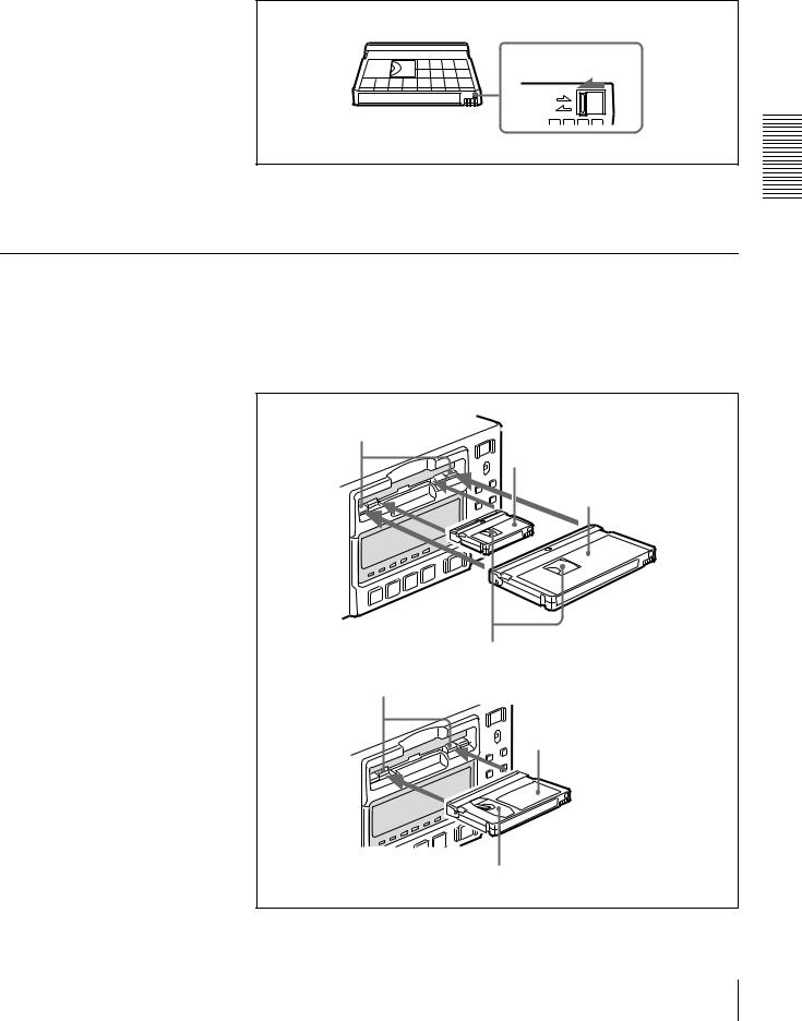
Preventing accidental erasure
Set the REC/SAVE switch on the cassette to SAVE to prevent accidental erasure of recorded contents.
REC/SAVE switch
Set to SAVE
REC
SAVE
To enable re-recording
Set the REC/SAVE switch to REC.
When this switch is set to SAVE, the unit cannot record on the tape.
Inserting and Ejecting Cassettes
Inserting a cassette
This unit accepts three sizes of cassette: L (standard size), M (medium size: DVCPRO) and S (mini size). When inserting a cassette in the unit, make sure its tape window faces upward as shown in the following figure.
Outer guides
Mini size (Insert the cassette into the middle of the cassette compartment.)
Standard size
Tape window facing upward
Inner guides
Medium size (Align the cassette with the outer guides, then slide it in over the inner guides.)
Tape window facing upward
Playback and Recording 2 Chapter
Usable Cassettes 29
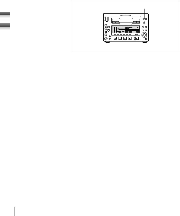
No double insertion of cassettes
When you insert a cassette, the orange lock-out plate appears in the cassette compartment to prevent double insertion.
Ejecting a cassette
Press the EJECT button.
Playback and Recording 2 Chapter
EJECT button
dB |
|
dB |
|
INPUT |
VIDEO |
AUDIO |
U-BIT |
SERVO |
|
CL REC INHI |
|
||
0 |
|
0 |
|
|
|
|
|||||||
|
|
|
|
V:SDTI COMPOSITE CH-1 1/2 CH-2 3/4 |
TC |
COUNTER |
|
NO EDIT |
REPEAT |
||||
-12 |
|
-12 |
|
SDTI |
S VIDEO |
ANALOG |
ANALOG |
|
|
|
|
|
|
-20 |
|
-20 |
|
i.LINK |
Y-R,B |
AES/EBU |
AES/EBU |
|
|
|
|
|
|
|
|
|
SDI |
SG |
SDI SG |
SDI SG |
|
|
|
|
|
||
-30 |
|
-30 |
|
OUTPUT |
|
AUDIO |
|
|
|
|
|
||
-40 |
|
-40 |
|
|
VIDEO |
HOURS |
MINUTES |
SECONDS |
FRAMES |
||||
-60 |
|
-60 |
|
SDI |
COMPOSITE |
CH 1/2 |
|||||||
|
|
SDTI |
S VIDEO |
CH 3/4 |
PB FS |
REC MODE |
VITC |
REMOTE |
|||||
CH- 1 |
3 |
CH- 2 |
4 |
|
Y-R,B |
|
|
48K 44.1K 32K |
2CH 4CH |
EDIT MODE |
9P i.LINK |
||
REW |
PLAY |
F FWD |
STOP |
REC |
30 Usable Cassettes
 Loading...