


CT-X442

SERVICE MANUAL
RADIO SECTION
(FM)
Frequency Range: 87.5 MHz – 108 MHz
Intermediate frequency: 10.7 MHz
Usable Sensitivity: 12.7 dBf
50 dB Quieting Sensitivity: 17.2 dBf
IF Rejection: 100 dB
Frequency Response: 30 Hz – 15,000 Hz
S/N Ratio: 67 dB
Stereo Separation: 35 dB at 1 kHz
Alternate Channel Selectivity: 90 dB
Capture Ratio: 3 dB
(MW)
Frequency Range: 531 kHz – 1,602 kHz
Intermediate frequency: 10.71 MHz/450 kHz
Usable Sensitivity: 30 µV (30 dB)
(LW)
Frequency Range: 144 kHz – 288 kHz (1-kHz/9-kHz
steps)
Intermediate frequency: 10.71 MHz/450 kHz
Usable Sensitivity: 30 µV (30 dB)
TAPE SECTION
Tape Speed: 4.8 cm/sec.
S/N Ratio: 50 dB
Frequency Response: 40 Hz – 14,000 Hz
Stereo Separation: 40 dB
FM/MW/LW CASSETTE CAR STEREO
AEP Model
UK Model
SPECIFICATIONS
CT-X442
Ver 1.0 2003.02
Model Name Using Similar Mechanism NEW
Tape T r ansport Mechanism Type CDS-363AG1-A
9-877-054-01 Sony Corporation
2003B0500-1 e Vehicle Company
C 2003.02 Published by Sony Engineering Corporation
AUDIO SECTION
Max. Power Output: 40 W × 4 channels
AUX input
Input sensitivity (load impedance) AUX: 300 mV
(10 kΩ)
GENERAL
Power-Supply Voltage: 14.4 V (11 to 16 V
allowable), DC, negative ground
Load Impedance: 4 Ω
Tone Control: Bass ± 10 dB at 100 Hz, Treble
± 10 dB at 10 kHz
Preamp Output Voltage (load impedance): 2.2 V
(10 kΩ)
Installed size: 182 (W) × 53 (H) × 155 (D) mm
Supplied Accessory: Carrying case (1)
•Specifications and external appearance are subject to
change without notice due to product improvement.
• The tuner section adjustments are done automatically in this
set.

2
CT-X442
Notes on chip component replacement
•Never reuse a disconnected chip component.
• Notice that the minus side of a tantalum capacitor may be dam-
aged by heat.
Flexible Circuit Board Repairing
•Keep the temperature of the soldering iron around 270 ˚C dur-
ing repairing.
• Do not touch the soldering iron on the same conductor of the
circuit board (within 3 times).
• Be careful not to apply force on the conductor when soldering
or unsoldering.
TABLE OF CONTENTS
1. GENERAL ................................................................... 3
2. DISASSEMBLY
2-1. Disassembly Flow ........................................................... 6
2-2. Mechanical Deck Assy (CDS-363AG1-A)..................... 7
2-3. Sub Panel Assy ................................................................ 8
2-4. MAIN Board ................................................................... 9
3. DIAGRAMS
3-1. Note for Printed Wiring Boards and
Schematic Diagrams ....................................................... 10
3-2. Printed Wiring Board – MAIN Board – ........................ 11
3-3. Schematic Diagram – MAIN Board (1/3) – .................. 12
3-4. Schematic Diagram – MAIN Board (2/3) – .................. 13
3-5. Schematic Diagram – MAIN Board (3/3) – .................. 14
3-6. Printed Wiring Boards – KEY/AUX Boards –.............. 16
3-7. Schematic Diagram – KEY/AUX Boards – .................. 17
3-8. IC Pin Function Description ........................................... 18
4. EXPLODED VIEWS
4-1. Main Section ................................................................... 20
4-2. Front Panel Section ......................................................... 21
5. ELECTRICAL PARTS LIST ............................... 22
3
CT-X442
SECTION 1
GENERAL
This section is extracted from
instruction manual.
ENGLISH
2
ENGLISH
2
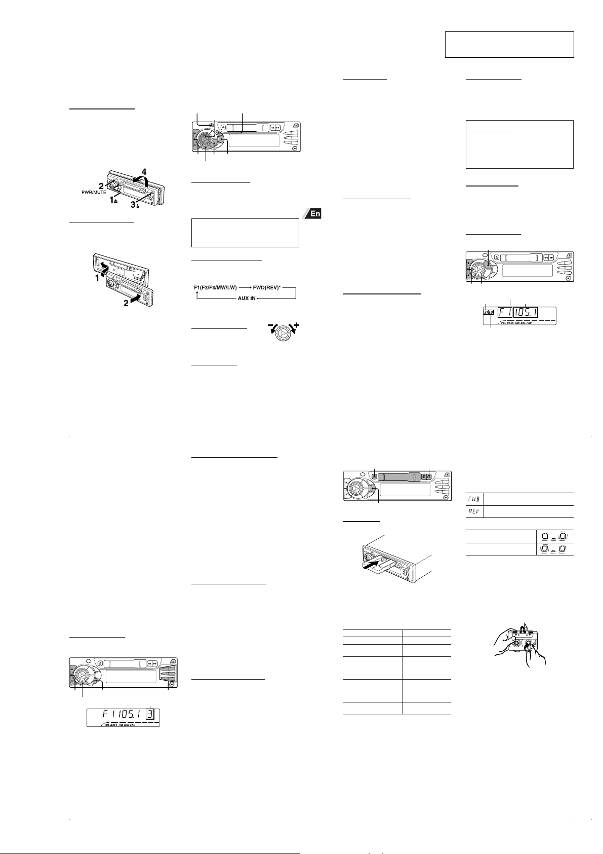
THEFT PROTECTION
Take the front panel with you when leaving the car, and
keep it in the supplied carrying case.
Detaching the front panel
Before detaching the front panel, remove the cassette to
prevent possible damage to the unit.
1 Press z to remove the cassette.
2 Press and hold PWR/MUTE until the unit turns off.
3 Press %. (Hold the panel with one hand to prevent
accidentally dropping it.)
4 Remove the panel.
Attaching the front panel
1 Engage the left side of the front panel to the left catch
on the unit.
2 Push the panel forward until it locks. Be sure not to
press any buttons while you are attaching the panel.
Note
Do not touch the connector on the reverse side of the
front panel. This could cause a poor or faulty connection.
BASIC OPERATION,
AUDIO AND CLOCK
ADJUSTMENT
PWR/MUTE SEL
DSPL
TU (TUNER)
SRC
AUDIO CONTROL
i
/
k
Turning the unit on/off
•You can turn the unit on by pressing any button on the
front panel except %, z, f, g and AUDIO
CONTROL. The unit also turns on when you insert a
cassette.
•Press and hold PWR/MUTE until the unit turns off.
Note
Most operations described in this manual require
the unit to be turned on before starting the operation,
unless explicitly stated otherwise.
Changing the source mode
1 Press SRC.
Pressing SRC cycles through source modes in the
following order:
* Tape Play mode (available while a cassette is in the
unit)
Adjusting the volume
1 Turn AUDIO CONTROL.
VOL (volume)
indicator flashes.
Muting the sound
1 Press PWR/MUTE briefly.
MT indicator flashes.
To restore volume, briefly press PWR/MUTE again.
3
ENGLISH
3
ENGLISH
Adjusting sound
You can select the following modes for adjusting sound
depending on the music you listen to: BASS (low
frequencies), TRE (high frequencies), BAL (left/right),
FAD (front/rear) and H-BASS (high bass).
1 Press SEL repeatedly to select the mode to be
adjusted.
Pressing SEL cycles through the modes. The
selected mode’s indicator flashes (except for H-
BASS).
2 Turn AUDIO CONTROL to increase or decrease the
level for the selected mode (except for H-BASS).
In H-BASS mode, turn AUDIO CONTROL to select
1, 2, 3 or off.
Note
Adjust the level or select on/off within 5 seconds, or the
selected mode will return to previous state.
Aligning the source levels
(Source Level Adjuster)
Volume may vary each time you change the source
mode. In this case, you can align each source mode’s
volume to almost the same level.
1 Press SRC or TU (TUNER) repeatedly to select the
desired mode.
2 Press DSPL while pressing SEL.
“LEVEL 0” appears on the display.
3 Turn AUDIO CONTROL to adjust the level.
Note
Adjust the level within 5 seconds, or the selected mode
will be canceled.
Restoring the factory settings
1 Turn off the unit.
2 Press and hold DSPL until “LEVEL --” appears on
the display.
Note
You can restore the factory settings only for VOL, BASS,
TRE, BAL, FAD, and H-BASS, and aligned source
volume levels.
Setting the beep tone
1 Turn off the unit.
2 Press and hold SEL until “BEEP” appears on the
display.
3 Turn AUDIO CONTROL to select ON or OFF.
4 Press SEL.
Setting the clock
1 Press and hold DSPL until the clock indication
flashes in the display.
2 Press i (to set hour) or k (to set minute) and
turn AUDIO CONTROL.
3 Press DSPL.
Displaying the clock
1 Press DSPL.
To return to the former display, press DSPL again.
RADIO OPERA TION
Tuning in to a station
(Seek/Manual Tuning)
LO
i
/
k
TU (TUNER)
Band indicator*
Stereo indicator Frequency indication
Local indicator
*“F” means FM.
ENGLISH
4
ENGLISH
4
1 Press TU (TUNER) repeatedly to select the desired
band (F1, F2, F3, MW, or LW).
2* Press i (to move to higher frequencies) or k (to
move to lower frequencies) to tune in to a station.
“ST” appears on the display when an FM station is
broadcasting in stereo, and receiving conditions are
good.
*Seek Tuning and Manual Tuning
•Press and hold i or k until Seek Tuning starts.
The unit locates a station automatically (Seek
Tuning).
•Press i or k repeatedly to search for a desired
station while increasing or decreasing the frequency
step by step (Manual Tuning).
To stop Seek Tuning, press i or k again.
Monaural mode
When FM signals become weak, or FM reception
becomes poor, the unit automatically switches to
Monaural mode to reduce noise.
Local mode
Local mode allows you to tune in only to strong stations
during Seek Tuning.
1 Press LO before you start Seek Tuning.
“LO” appears on the display.
To return to Distant mode, press LO again.
“LO” disappears and the unit tunes in to all receivable
stations.
Using preset stations
You must preset stations before you can tune in to a
station using preset station number buttons.
i
/
k
PS/A.ME
TU (TUNER)
Preset station buttons 1 to 6
Preset station number
Presetting stations automatically
(Auto Memory)
1 Press TU (TUNER) repeatedly to select the desired
band (F1, F2, F3, MW, or LW).
2 Press and hold PS/A.ME until automatic presetting
starts.
The unit automatically stores up to 6 stations for
each band.
After completion of automatic presetting, the unit
tunes in to all the stations stored on the preset
station buttons in order (Preset Scan).
To cancel automatic presetting, press PS/A.ME again.
Checking the preset stations (Preset Scan)
1 Press PS/A.ME briefly.
Each preset station will be tuned in for 5 seconds in
order.
To cancel Preset Scan, press PS/A.ME again or any
preset station button.
Presetting stations manually
(Manual Memory)
1 Press TU (TUNER) repeatedly to select the desired
band (F1, F2, F3, MW, or LW).
2 Press i or k to tune in to a desired station (see
“Tuning in to a station” as well for another tuning
method).
3 Press and hold the desired preset station button until
the unit beeps.
Note
A newly preset station replaces the station on the same
band that was previously stored on that preset station
button.
Tuning in to a preset station
1 Press TU (TUNER) repeatedly to select the desired
band (F1, F2, F3, MW, or LW).
2 Press the preset station button on which the desired
station is stored.
Active tuning reception control (ATRC)
The unit automatically suppresses FM noise caused by
vehicle movement, and maintains sound quality.
TAPE PLAYBACK
SRC
gfz
Playing a tape
1 Insert a cassette to start playback.
If a cassette is already inserted, press SRC
repeatedly to select Tape Play mode to start
playback.
Playback starts in the direction that the unit played
back previously.
Press the following buttons to operate tape transport.
5
ENGLISH
To
Eject a cassette*
Change the playback side
Fast-forward the upper side
(l) of the tape
Rewind the lower side (j)
of the tape
Rewind the upper side (l)
of the tape
Fast-forward the lower side
(j) of the tape
Stop fast transport and
resume playback
Press
z
f and g
simultaneously
g
f
f or g lightly**
Auto Reverse function
When the end of the tape is reached during playback or
fast tape transport, the direction of the tape is
automatically reversed, and playback starts on the other
side.
Direction indications
Displayed when the upper side of the
cassette is being played.
Displayed when the lower side of the
cassette is being played.
Tape transport display
Upper side: During playback
Lower side: During playback
When you do not play back a tape
Be sure to eject any cassette.
To prevent tape problems
Before inserting a cassette into the unit, make sure that
there is no slack in the tape. If necessary, take up the
slack by inserting a pencil through the spindle hole and
winding.
Tapes of 90 minutes or longer are extremely thin and
easily deformed or damaged. They are not
recommended.
*When you eject the cassette, the unit switches to the
previous mode.
** Do not press f or g all the way. Doing so may
change the direction of tape transport.

4
CT-X442
AUXILIARY EQUIPMENT
Listening to a CD/MD/MP3 portable
player or other equipment
You can listen to equipment connected to the unit. Refer
to the operating instructions for the corresponding
equipment for more detailed information.
Be sure to remove the inserted cassette to prevent
possible damage to the unit before connecting the
equipment.
SRC
AUX jack
1
Connect a CD/MD/MP3 portable player or other
equipment to the unit’s AUX jack (3.5-mm dia.).
2
Press SRC repeatedly until “AUX IN” appears on the
display.
OTHER FUNCTIONS
SRC SELAUDIO
CONTROL
Changing the contrast of the display
1
Press and hold SRC until “CONT.” appears on the
display.
2
Turn AUDIO CONTROL to select “L (for low)” or “H
(for high).”
Setting the dimmer of the display
1
Press and hold SEL until “DIMMER” appears in the
display.
2
Turn AUDIO CONTROL to select “0 (bright)” or
“1 (dimmed).”
Muting the sound while using the phone
When the telephone mute lead (light blue) of the unit is
connected to a cellular phone hands-free car kit, etc.,
the unit mutes the sound from the speakers
automatically during your conversation on the cellular
phone.
For details, refer to the separate “INSTALLATION AND
CONNECTIONS” for the unit and the instruction manual
for the cellular phone hands-free car kit.
ENGLISH
SUPPLIED MOUNTING HARDWARE FOR
INSTALLATION → A
INSTALLATIONS
The installation scenario described in this manual
assumes that you have a typical car. If your specific car
requires any adjustments or modifications, consult your
nearest AIWA car audio dealer.
PRECAUTIONS
• This unit is designed for negative-ground, 12-V DC
operation only.
• Before starting installation, make sure the ignition switch
is set to OFF and disconnect the earth terminal of the
car battery to avoid short-circuiting.
• Install the unit where it will not hamper the operation of
the vehicle.
• Install the unit where it will not injure the passenger if
there is a sudden stop, like an emergency stop.
• Avoid installing the unit where it would be subject to high
temperatures caused by direct sunlight or hot air from
the heater, or where it would be subject to dust, dirt or
excessive vibration.
• Use only the supplied mounting hardware, for a safe
and secure installation.
PREINSTALLATIONS → B
If there is installation hardware for another receiver
already in the dashboard, it must be removed.
Before installing the unit in the dashboard
Remove the trim plate from the unit → 1
• FLAP (flap panel)-type model Remove the trim plate
a by pushing the side of the plate in the direction of the
arrow.
• FIX (fixed panel)-type model Remove the trim plate
a by pushing the upper and lower parts of the plate in
the direction of the arrow.
• As for the DFP (Detachable Front Panel) -type model,
the trim plate is separately packed at the factory.
Remove the installation sleeve → 2
Insert the levers 8 along each groove on both sides of
the unit to unlock the installation sleeve 1 and pull the
sleeve to detach it from the unit.
BASIC INSTALLATIONS → C
Installation in the dashboard
Note that the Installation shown is a typical example.
For some car types you may need to make adjustments
or modifications to install the unit. If your car is of such
type, consult your nearest AIWA car audio dealer.
Mounting-angle adjustment
The mounting angle should be 30 degrees or less from
horizontal.
Caution on installation without using the
sleeve → D
Be sure to use the supplied screws 9 shown
in A to attach the mounting brackets M (not
supplied).
ESPAÑOL
ACCESORIOS DE MONTAJE SUMINISTRADOS
PARA LA INSTALACION
→ A
INSTALACION
La instalación descrita a lo largo de este manual
presupone que tiene un coche normal. Si su coche
requiere ajustes o modificaciones, consulte con su
concesionario de audio para coches de AIWA más
cercano.
PRECAUCIONES
• Este aparato fue diseñado para una conexión a tierra
negativa y funciona con una CC de 12 V.
• Antes de empezar la instalación, compruebe que el
interruptor de encendido está en OFF y desconecte el
terminal a tierra de la batería de coche para evitar un
cortocircuito.
• Instale el aparato donde no moleste el funcionamiento
del vehículo.
• Instale el aparato en un lugar donde no provoque
heridas a los pasajeros por un frenado repentino, como
en el caso de un frenado de emergencia.
• Evite instalar el aparato donde quede expuesto a altas
temperaturas provocadas por los rayos directos del sol
o el aire caliente de la calefacción o donde pueda estar
expuesto al polvo, suciedad o vibraciones excesivas.
• Utilice sólo los accesorios de montaje suministrados,
para una instalación firme y segura.
INSTALACION PREVIA → B
Si ya se han instalado accesorios para instalación de otro
aparato en el tablero, deberá desmontarlos.
Antes de instalar el aparato en el cubretablero
Desmonte la placa de adorno del aparato → 1
• Modelo de tipo FLAP (panel de aleta) Desmonte la
placa de adorno a empujando el lado de la placa en el
sentido de la flecha.
• Modelo de tipo FIX (panel fijo) Desmonte la placa de
adorno a empujando las partes superior e inferior de
la placa en el sentido de la flecha.
• Para el modelo de tipo DFP (Panel frontal
desmontable), la placa de adorno se empaqueta por
separado en la fábrica.
Desmonte el manguito de instalación → 2
Inserte las palancas 8 a lo largo de cada ranura en
ambos lados del aparato para destrabar el manguito de
instalación 1 y tire del manguito para desmontarlo de la
del aparato.
INSTALACION BASICA → C
Instalación en el tablero
Tenga en cuenta que la instalación que se describe es a
modo de ejemplo. Para algunos modelos de coche,
puede ser necesario hacer ajustes o modificaciones
para instalar el aparato. Si su coche es de este tipo,
consulte con su concesionario de audio para coches de
AIWA más cercano.
Ajuste del ángulo de montaje
El ángulo de montaje debe ser de 30 grados o menos de
la horizontal.
Precauciones sobre la instalación sin
utilizar el manguito → D
Se deben utilizar siempre los tornillos
suministrados 9 que aparecen en A, para
instalar las ménsulas de montaje M (no
suministradas).
FRANÇAIS
MATERIEL DE MONTAGE FOURNI POUR
L’INSTALLATION → A
INSTALLATION
Le scénario d’installation indiqué dans ce manuel
présuppose une voiture typique. Si votre voiture exige un
ajustement ou une modification, consultez le revendeur
de chaîne audio automobile AIWA le plus proche.
PRECAUTION
• Cet appareil est conçu uniquement pour le
fonctionnement sur courant continu 12 V, masse
négative.
• Avant de commencer l’installation, vérifiez que le
commutateur d'allumage est réglé à OFF et déconnectez
la prise de masse de la batterie auto pour éviter tout
court-circuit.
• Installez l’appareil à un endroit où il ne gênera pas le
fonctionnement de la voiture.
• Installez l’appareil à un endroit où il ne blessera pas le
passager, en cas d’arrêt brutal, par exemple un arrêt
d’urgence.
• Evitez d’installer l’appareil à un endroit en plein soleil ou
sous l’air chaud du chauffage, où il sera soumis à des
températures élevées, ou bien à un endroit où il sera
soumis à une poussière, de la saleté ou de fortes
vibrations.
• Utilisez seulement le matériel de montage fourni pour
assurer une installation sûre et solide.
PREPARATIFS POUR L’INSTALLATION
→ B
S’il y a déjà du matériel de montage pour un autre
récepteur dans le tableau de bord, il doit être retiré.
Avant d’installer l’appareil dans le tableau de bord
Retirez la plaque d’ajustement de l’appareil → 1
•
Modèle de type FLAP (panneau basculant) Retirez la
plaque d’ajustement
a
en poussant le côté de la plaque
dans le sens de la flèche.
• Modèle de type FIX (panneau fixe) Retirez la plaque
d’ajustement a en poussant les parties haut et bas de
la plaque dans le sens de la flèche.
• Comme pour le modèle de type DFP (panneau avant
amovible), la plaque d’ajustement est emballée
séparément à l’usine.
Retirez le manchon d’installation → 2
Insérez les leviers 8 le long de chaque cannelure sur les
deux côtés de l’appareil pour débloquer le manchon
d’installation 1, puis tirez sur le manchon pour le détacher
de l’appareil.
INSTALLATION DE BASE → C
Installation dans le tableau de bord
Pour certains types de voiture, il faudra peut-être faire
des ajustements ou modifications pour installer l’appareil.
Si c’est le cas pour votre voiture, consultez le revendeur
de chaînes audio automobiles AIWA le plus proche.
Ajustement de l’angle de montage
L’angle de montage doit être de 30˚ ou moins de
l’horizontale.
Précaution pour l’installation sans manchon
→ D
Utilisez les vis fournies 9 indiquées dans A
pour attacher les fixations de montage M (non
fournies).
DEUTSCH
MITGELIEFERTE BEFESTIGUNGSTEILE
ZUR INSTALLATION → A
INSTALLATIONEN
Das in dieser Anleitung beschriebene Installationsszenarium
bezieht sich auf ein typisches Fahrzeug. Falls Ihr Fahrzeug
spezielle Einstellungen oder Modifikationen erfordert, fragen
Sie bei Ihrem AIWA-Autoradio-Fachhändler nach.
ZUR BESONDEREN BEACHTUNG
• Dieses Gerät ist zum Betrieb mit einer 12-Volt-
Fahrzeuganlage mit negativer Masse ausgelegt.
• Schalten Sie vor dem Einbau die Zündung aus und
klemmen Sie das Massekabel der Autobatterie ab,
damit kein Kurzschluß auftreten kann.
• Das Gerät immer so installieren, daß es nicht die
Bedienung des Fahrzeugs behindert.
• Das Gerät so installieren, daß es nicht Insassen im
Falle plötzlichen Bremsens, wie etwa bei einer
Notbremsung, verletzen kann.
• Das Gerät nicht an Orten installieren, wo es hohen
Temperaturen durch direktes Sonnenlicht oder Heißluft
von der Heizung, Staub, Schmutz oder starken
Vibrationen ausgesetzt ist.
• Zur sicheren und festen Installation die mitgelieferten
Einbauteile verwenden.
INSTALLATIONSVORBEREITUNGEN → B
Wenn bereits Hardware für einen anderen Receiver im
Armaturenbrett vorhanden ist, muß diese entfernt werden.
Vor dem Einbau des Geräts in das Armaturenbrett
Nehmen Sie die Deckplatte vom Gerät ab → 1
• FLAP-Typ-Modell Zum Abnehmen der Deckplatte a
drücken Sie in Pfeilrichtung auf die Seitenkante der
Platte.
• FIX-Typ-Modell Zum Abnehmen der Deckplatte a
drücken Sie in Pfeilrichtung auf die Ober- und Unterkante
der Platte.
• Beim DFP-Typ-Modell, Die Deckplatte wird werkseitig
separat verpackt.
Die Installationsmuffe entfernen → 2
Die Hebel 8 entlang jeder Rille an beiden Seiten des
Geräts einsetzen, um die Installationsmuffe 1 zu lösen
und die Muffe vom Gerät abziehen.
M5 × 6 mm
M5 × 6 mm
23
FIXFLAP
5
CT-X442
10A
ENGLISH
CONNECTIONS
PRECAUTIONS
Precaution on making connections
Before connecting, make sure that the ignition switch is
set to OFF, and remove the earth terminal of the battery
to protect the unit and your car from damage.
Caution
Make the connections correctly, as illustrated in the
connection diagram.
Do not connect the negative ( cord of each speaker
wire to a common point. When replacing the fuse, be
sure to use a fuse of the same rated amperage. Use
of a fuse of a higher rating may cause serious
damage to the unit.
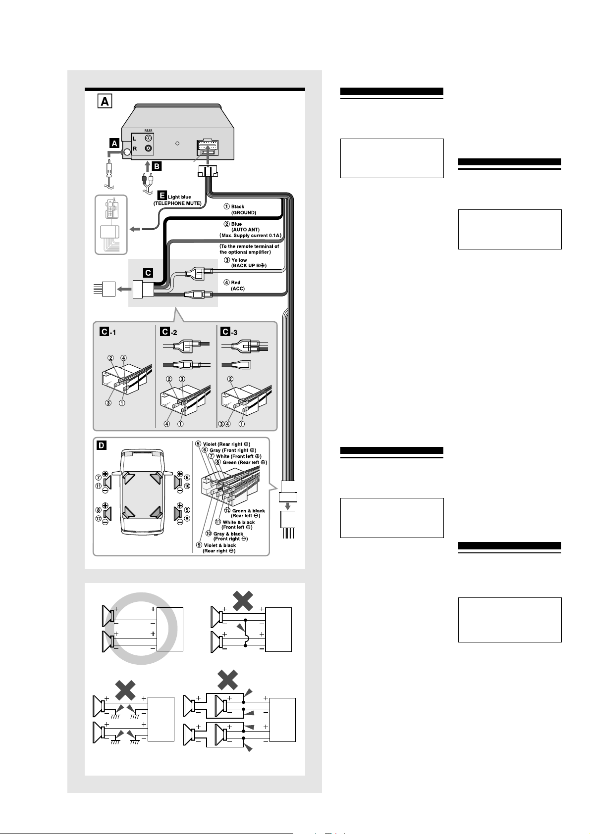
CONNECTION DIAGRAM → A
A From the car antenna
B To the input jack of the optional power
amplifier (for the rear channel)
C
To the ISO connector of the vehicle (power supply)
Make sure the pin arrangement of the power-supply
connector of your car conforms to that of the standard
ISO connector C-1.
Some car types may have a different pin arrangement,
C-2 or C-3. In that case, change the connections of the
red and yellow leads as shown in C-2 or C-3.
Note
If your car is not prefitted with ISO standard connectors,
you should use an adaptor available from your retailer or
any good automotive accessory shop.
Colors of leads
1
Black (ground lead to be connected to vehicle [metal] body.)
2 Blue (power antenna lead to be connected to the
terminal of the control relay switch for a vehicle
equipped with a fully automatic power antenna. This
lead is not used for a vehicle with a manual antenna
or a switch-operated power antenna. If you will use
the optional power amplifier with the unit, connect this
lead to the remote terminal of the amplifier.)
(Max. supply current 0.1 A)
3 Yellow (battery lead to be connected to the backup
terminal from which power is always supplied.)
4
Red (ACC lead to be connected to the terminal from which
power is supplied when the ignition switch is set to ACC.)
D To the ISO connector of the vehicle (speaker
connection)
Colors of leads
5/9
Violet/Violet & Black; Rear right )/(
6/0 Gray/Gray & Black; Front right
)/
(
7/! White/White & Black; Front left
)/
(
8/@ Green/Green & Black; Rear left
)/
(
Notes
• Use speakers with an impedance of 4 to 8 ohms and
with adequate power-handling capacities. Otherwise,
the speakers may be damaged.
• Do NOT connect the speakers in parallel.
• Do NOT connect the terminals of the speaker system to
the car chassis.
E To the radio mute lead of the cellular phone
hands-free car kit, etc.
When the telephone mute lead (light blue) is connected to
a cellular phone hands-free car kit, etc., the unit mutes the
sound from the speakers automatically during your
conversation on the cellular phone. For details, refer to the
instruction manual for the cellular phone hand-free car kit.
Note
This telephone mute lead supports connection only to the
radio mute line. When connected to another type of
output system, it will not work.
ESPAÑOL
CONEXIONES
PRECAUCIONES
Precauciones al hacer las conexiones
Antes de conectar, confirme que el interruptor de encendido
está en OFF y desmonte el terminal a tierra de la batería
para proteger el aparato y su coche contra daños.
Precaución
Haga las conexiones correctamente, tal como se
describe en el diagrama de conexiones.
No conecte el cable negativo
(
de cada cable de altavoz
a un punto común. Cuando cambie el fusible, utilice siempre
uno del mismo amperaje nominal. El uso de un fusible de
mayor régimen puede provocar daños importantes en el
aparato.
DIAGRAMA DE CONEXIONES → A
A De la antena del coche
B A la toma de entrada del amplificador de
potencia opcional (para el canal trasero)
C Al conector ISO del vehículo (alimentación
eléctrica)
Compruebe que la forma de patillas del conector de
alimentación eléctrica de su coche es un conector que
cumpla con la norma ISO C-1.
Algunos tipos de coche pueden tener otra forma de patillas
diferente,
C
-2 o
C
-3. En este caso, cambie las conexiones
de los cables rojo y amarillo como se indican en
C
-2 o
C
-3.
Nota
Si su coche no tiene conectores que cumplan la norma ISO,
debe utilizar un adaptador de venta en su distribuidor o cualquier
tienda de accesorios para automóviles completa.
Colores de los cables
1 Negro (cable a tierra a conectar a la carrocería del
vehículo [metal].)
2
Azul (cable de antena motriz a conectar al terminal del
interruptor del relé de control para un vehículo equipado
con antena motriz totalmente automática. Este cable no
se debe utilizar en un vehículo con antena manual o
antena motriz que funcione mediante interruptor. Si
utiliza el amplificador de potencia opcional en esta unidad.
conecte este cable al terminal remoto del amplificador.)
(Corriente máxima 0,1 A)
3 Amarillo (cable de batería a conectar al terminal de
reserva con un flujo permanente de electricidad.)
4
Rojo (cable ACC a conectar al terminal que recibe eléctrica
cuando el interruptor de encendido está en ACC.)
D Al conector ISO del vehículo (conexión de
altavoces)
Colores de los cables
5/9 Violeta/Violeta y negro; parte posterior derecha )/(
6/0 Gris/Gris y negro; parte frontal derecha )/(
7/! Blanco/Blanco y negro; parte frontal izquierda )/(
8/@ Verde/Verde y negro; parte posterior izquierda )/(
Notas
•Utilice altavoces con una impedancia de 4 a 8 ohmios
y con suficiente capacidad eléctrica. De lo contrario
puede dañar los altavoces.
• NO conecte los altavoces en paralelo.
• NO conecte los terminales del sistema de altavoces al
chasis del coche.
L
R
R
L
L
R
L
R
E Al conductor de silenciamiento de radio
del kit de manos libres para el teléfono
celular de coche, etc.
Cuando el cable de silenciamiento (marrón) para teléfono
está conectado al kit de manos libres para teléfono
celular de coche, etc., la unidad silencia automáticamente
los altavoces durante su conversación en el teléfono
celular. Para más detalles, consulte el anual de
instrucciones del kit de manos libres para teléfono celular
de coche.
Nota
Este cable de silenciamiento de teléfono sólo puede
conectarse a la línea de silenciamiento de radio. No
funcionará si lo conecta a otro tipo de sistema de salida.
FRANÇAIS
CONNEXIONS
PRECAUTIONS
Précautions pour les connexions
Avant le raccordement, vérifiez que la clé d’allumage est
sur OFF, et débranchez la prise de terre de la batterie
pour protéger l’appareil et votre voiture des dommages.
Attention
Effectuez les connexions correctement, comme
indiqué sur le diagramme de connexion.
Ne raccordez pas le cordon négatif ( de chaque fil
de haut-parleur à un point commun. Au remplacement
du fusible, utilisez un fusible à ampérage nominal
identique. L’emploi d’un fusible à ampérage plus
élevé peut sérieusement endommager l’appareil.
DIAGRAMME DE CONNEXION → A
A De l’antenne du véhicule
B A la prise d’entrée de l’amplificateur de
puissance en option (pour le canal arrière)
C
Au connecteur ISO du véhicule (alimentation)
Vérifiez que l’agencement des broches du connecteur
d’alimentation du véhicule est conforme à celle du
connecteur ISO standard C-1.
Certains types de voiture peuvent avoir un agencement de broches
différent,
C
-2 ou
C
-3. Dans ce cas, modifiez les connexions des
fils rouge et jaune comme indiqué en
C
-2 ou
C
-3.
Remarque
Si votre voiture n’est pas dotée d’un connecteur standard
ISO, utilisez un adaptateur disponible chez votre revendeur
ou dans tout bon magasin d’accessoires automobiles.
Couleurs des fils
1 Noir (fil de mise à la terre à raccorder à la carrosserie
[métal] du véhicule.)
2 Bleu (fil d’antenne électrique à raccorder à la prise du
commutateur de relais de commande pour un véhicule
équipé d’une antenne électrique entièrement
automatique. Ce fil n’est pas utilisé sur les véhicules
à antenne manuelle ou antenne électrique opérée
par commutateur. Si vous souhaitez utiliser
l’amplificateur de puissance en option avec cet
appareil, raccordez ce fil à la prise de télécommande
de l’amplificateur.)
(Courant d’alimentation maxi. 0,1 A)
3 Jaune (fil de batterie à raccorder à la prise de secours
de laquelle l’alimentation se fait toujours.)
4 Rouge (fil ACC à raccorder à la prise à partir de
laquelle la puissance est fournie quand la clé
d’allumage est réglée sur ACC.)
D Au connecteur ISO du véhicule
(raccordement des enceintes)
Couleurs des fils
5/9 Violet/Violet et Noir; Arrière droite
)/(
6/0 Gris/Gris et Noir; Avant droite
)/(
7/! Blanc/Blanc et Noir; Avant gauche
)/(
8/@ Vert/Vert et Noir; Arrière gauche
)/(
Remarques
•Utilisez des enceintes à impédance de 4 à 8 ohms et
puissance nominale adéquate. Sinon elles seront
endommagées.
• Ne raccordez PAS les enceintes en parallèle.
• Ne raccordez PAS les prises du système d’enceintes
au châssis de la voiture.
E Au conducteur d’assourdissement radio
du kit téléphone cellulaire auto mains libres
Quand le conducteur d’assourdissement radio (bleu ciel)
est relié à un kit téléphone cellulaire auto mains libres,
etc., l’appareil assourdit automatiquement le son des
enceintes pendant la conversation au téléphone cellulaire.
Pour les détails, consultez le mode d’emploi du kit
téléphone cellulaire auto mains libres.
Remarque
Le fil d’assourdisseur pour téléphone automobile peut
seulement être raccordé à la ligne d’assourdisseur radio.
Il sera sans effet s’il est raccordé à un autre type de
système de sortie.
DEUTSCH
ANSCHLÜSSE
VORSICHTSMASSREGELN
Vorsichtsmaßregel zur Herstellung von Anschlüssen
Vor dem Herstellen von Anschlüssen sicherstellen, daß
der Zündschalter auf OFF steht und die Masseklemme
der Batterie entfernen, um das Gerät und das Fahrzeug
vor Schäden zu schützen.
Vorsicht
Die Verbindungen korrekt herstellen, wie im
Anschlußdiagramm gezeigt.
Nicht die negative ( Leitung jedes
Lautsprecherkabels an einen gemeinsamen Punkt
anschließen. Beim Austauschen der Sicherung immer
eine Sicherung der gleichen Stärke verwenden.
Verwendung einer höheren Sicherung kann zu
schweren Schäden am Gerät führen.
ANSCHLUSSDIAGRAMM → A
A Von der Autoantenne
B Verstärkerendstufe (für hinteren Kanal)
C Zum ISO-Anschluß des Fahrzeug
(Betriebsstromversorgung)
Stellen Sie sicher, daß die Pinanordnung der
Betriebsstrombuchse des Fahrzeugs der Standard-ISO-
Buchse C-1 entspricht.
Bestimmte Fahrzeugtypen können eine andere
Pinanordnung haben, C-2 oder C-3. In diesem Fall
ändern Sie die Verbindungen der roten und gelben
Leitungen wie in C-2 oder C-3 gezeigt.
Hinweis
Wenn Ihr Fahrzeug nicht bereits mit ISO-
Standardbuchsen ausgestattet ist, sollten Sie einen
Adapter verwenden, der von Ihrem Fachhändler oder
einem guten Automobilzubehörgeschäft erhältlich ist.
Leitungsfarben
1 Schwarz (Masseleitung zum Anschluß an die
Fahrzeugkarosserie [Metall].)
2
Blau (Motorantennenleitung zum Anschluß an die Klemme
des Relaisschalters für ein Fahrzeug, das mit
vollautomatischer Motorantenne ausgestattet ist. Diese
Leitung wird nicht für ein Fahrzeug mit manueller Antenne
oder einer schalterbetriebenen Motorantenne verwendet.
Wenn Sie die optionale Verstärkerendstufe mit dem Gerät
verwenden wollen, diese Leitung an die
Fernbedienungsklemme des Verstärker anschließen.)
(Max. Versorgungsstrom 0,1 A)
CT-X442
6
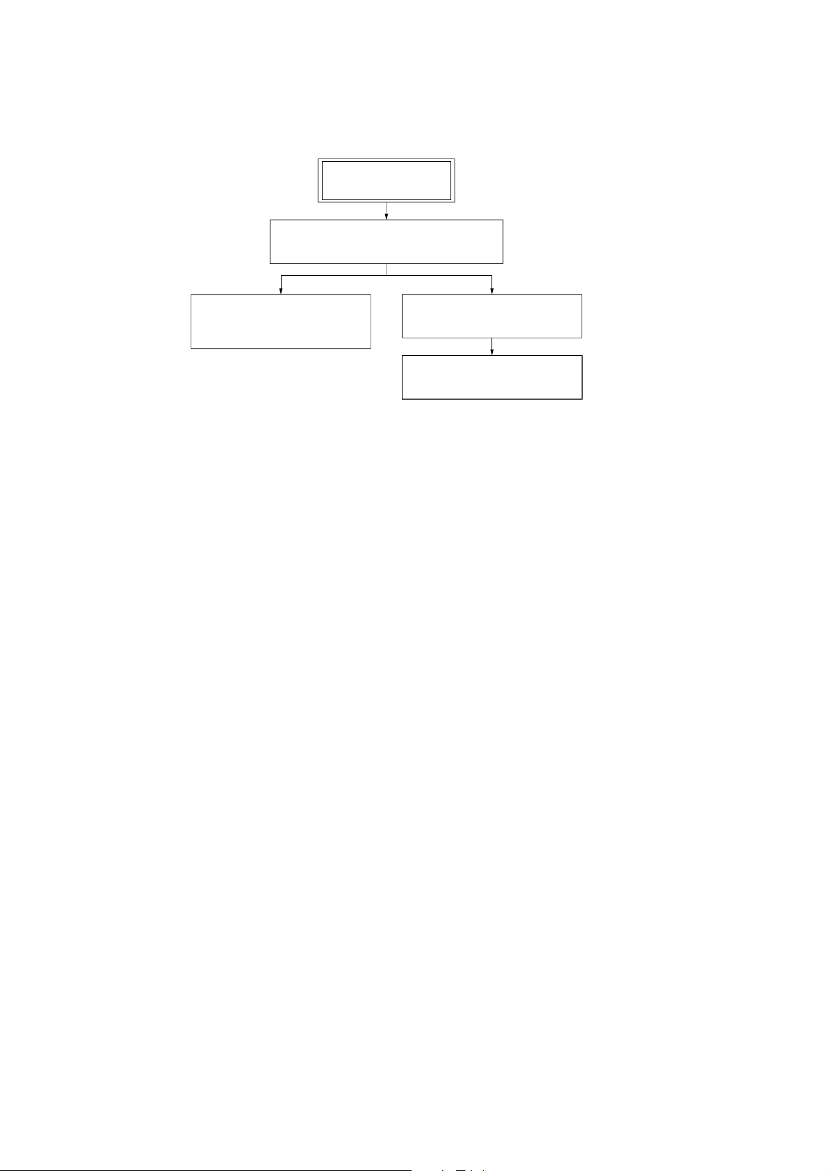
SET
2-3. SUB PANEL ASSY
(Page 8)
FRONT PANEL SECTION
(Note: Illustration of disassembly is omitted.)
2-2. MECHANICAL DECK ASSY
(CDS-363AG1-A)
(Page 7)
2-4. MAIN BOARD
(Page 9)
SECTION 2
DISASSEMBLY
• This set can be disassembled in the order shown below.
2-1. DISASSEMBLY FLOW

CT-X442
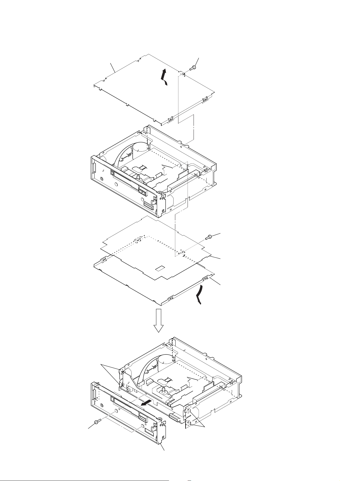
7
Note: Follow the disassembly procedure in the numerical order given.
2-2. MECHANICAL DECK ASSY (CDS-363AG1-A)
1
screw
(PTT2.6
×
4)
2
cover
4
two screws
(PTT2.6
×
5)
9
mechanical deck assy
(CDS-363AG1-A)
5
connector
(CN202)
8
connector
(CN201)
6
two convexes
7
3
screw
(PTT2.6
×
6)
CT-X442
8
2-3. SUB PANEL ASSY
1
screw
(PTT2.6
×
4)
2
cover
3
screw
(PTT2.6
×
4)
5
insulation sheet
4
cover
6
two screws
(PTT2.6
×
6)
8
sub panel assy
7
two claws
7
two claws
 Loading...