


CPD-200GS
Table of contents
 Loading...
CPD-200GS
CPD-200GS
SERVICE MANUAL
CPD-200GS
U/C MODEL
Chassis No. SCC-L07A-A
Picture tube
Video image area
Logical resolution
Physical resolution
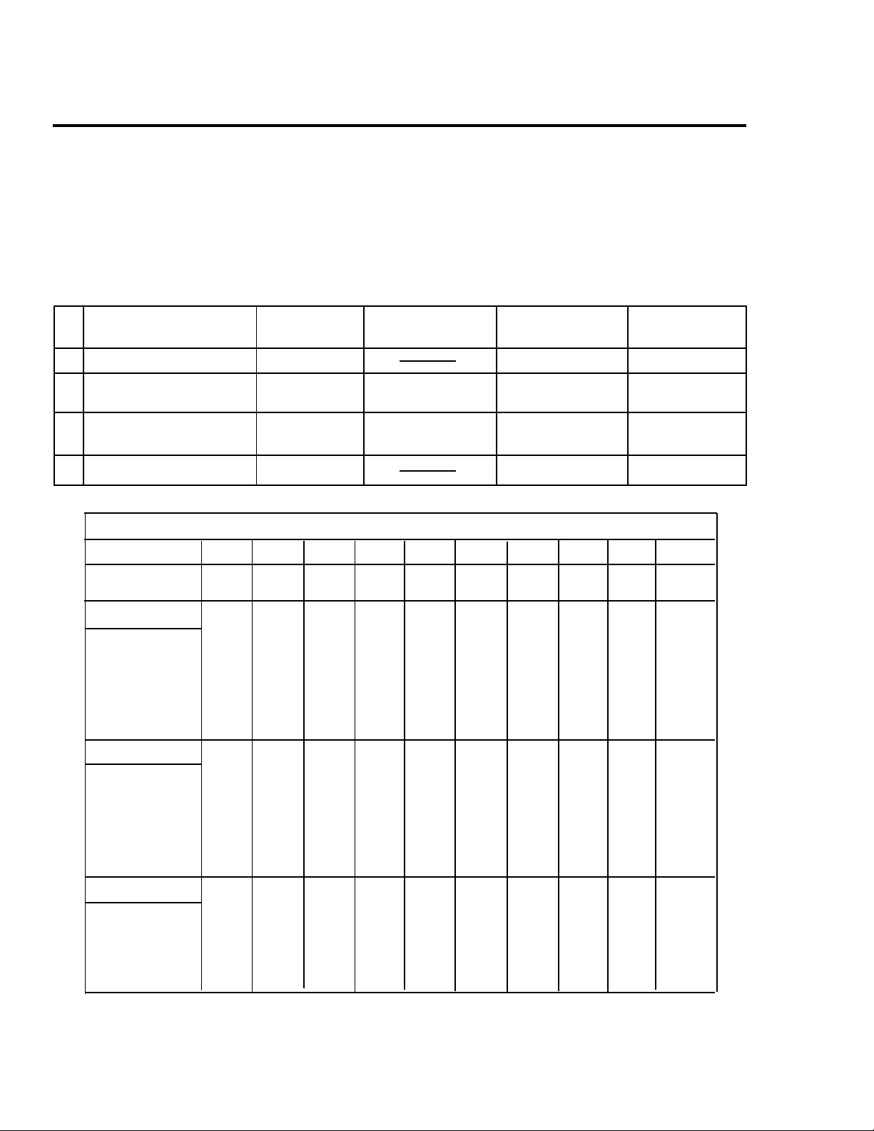
SPECIFICATIONS
0.25 mm aperture grill pitch
17 inches measured diagonally
90-degree deflection
(16" maximum viewing image)
Approx. 329.5 x 243 mm (w/h)
5/8
(13 x 9
Horizontal: Max. 1280 dots
Vertical: Max. 1024 lines
Horizontal: Max. 1024 dots
Vertical: Max. 768 lines
inches)
D-1H
Standard image area
Deflection frequency
AC input voltage / current
Dimensions
Mass
Design and specifications are subject to change without notice.
Approx. 312 x 234 mm (w/h)
(12
Horizontal: 30 to 85 KHz
Vertical: 50 to120 Hz
100 to 240 V, 50-60 Hz, 1.9 - 1.1 A
406 x 432 x 420 mm (w/h/d)
(16 x 17
Approx. 18.0 kg (39 lb 11 oz)
CHASSIS
3/8
1/4
x 9
inches)
1/8
5/8
x 16
inches)
COLOR COMPUTER DISPLAY
— 1 —
CPD-200GS
POWER SAVING FUNCTION
This monitor meets the power saving guidelines set
by the EPA Energy Star Program as well as the more
stringent TC092 guidelines (NUTEK). It is capable of
reduced power consumption when used with a computer equipped with Display Power Management Signaling (DPMS). By sensing the absence of the sync
signal coming from the computer, it will reduce the
CAUTION:
The Power Saving function will automatically put the monitor into Active-off state
if the power switch is turned on without
any video signal input. Once the horizontal and vertical syncs are sensed, the monitor will automatically return to its Normal
operation state.
power consumption as follows:
State Power Required u Power indicator POWER SAVING
consumption resumption time indicator
1
2
3
4
Normal Operation 100% green on off
Suspend
approx. 13% approx. 5 sec. green on orange on
(1st step of power saving)
Active-off
(2nd step of power saving)
Power - Off
approx. 7% approx. 15 sec. off orange on
0% off off
TIMING SPECIFICATION
MODE 1 2 3 4 5 6 7 8 9 10
Resolution (H x V)
Dot Clock (MHz)
640 X 480
25.175
800 X 600
49.500
800 x 600
56.250
832 X 624
57.283
1024 x 768
78.750
1024 x 768
80.000
1024 x 768
94.500
720 x 400
28.322
640 x 480
36.000
1280 x 1024
135.000
HORIZONTAL
Hor. Freq. (kHz)
H-Total
H-Blanking
H-Front Porch
H-Sync.
H-Back Porch
H-Active
(µsec)
VERTICAL
Ver. Freq. (Hz)
V-Total
V-Blanking
V-Front Porch
V-Sync.
V-Back Porch
V-Active
(lines)
SYNC.
Int(G)
Ext (H/V)/Polarity
Ext (CS)/Polarity
Int / Non Int
31.469
31.778
6.356
0.636
3.813
1.907
25.422
59.940
525
480
No
Yes -/-
No
Non Int
804
768
No
No
68.677
14.561
10.836
84.997
36
3
3
30
Yes +/+
Non Int
60.241
16.600
3.800
0.400
1.200
2.200
12.800
74.927
800
32
1
3
28
768
No
Yes -/-
No
Non Int
667
624
No
No
60.024
16.660
3.657
0.203
1.219
2.235
13.003
75.030
43
1
3
39
Yes +/+
Non Int
46.875
21.333
5.172
0.323
1.616
3.232
16.162
75.000
45
10
2
33
Yes +/+
Non Int
625
600
No
No
53.674
18.631
4.409
0.569
1.138
2.702
14.222
85.061
25
1
3
21
Yes +/+
Non Int
49.725
20.111
5.586
0.559
1.117
3.910
14.524
74.550
631
31
1
3
27
600
No
Yes -/-
No
Non Int
3.725
0.508
1.016
2.201
808
768
No
No
31.469
31.777
6.355
0.636
3.813
1.907
25.422
70.087
40
1
3
36
Yes -/+
Non Int
449
400
No
No
43.269
23.111
5.333
1.556
1.556
2.222
17.778
85.008
509
49
12
2
35
480
Yes -/-
Non Int
No
No
79.976
12.504
3.022
0.119
1.067
1.837
9.481
75.025
29
1
3
25
1066
42
1
3
38
1024
No
Yes +/+
No
Non Int
— 2 —
SAFETY CHECK-OUT
(US Model only)
CPD-200GS
After correcting the original service problem, perform
the following safety checks before releasing the set to the
customer:
1. Check the area of your repair for unsoldered or
poorly-soldered connections. Check the entire board
surface for solder splashes and bridges.
2. Check the interboard wiring to ensure that no wires
are “pinched” or contact high-wattage resistors.
3. Check that all control knobs, shields, covers, ground
straps, and mounting hardware have been replaced.
Be absolutely certain that you have replaced all the
insulators.
4. Look for unauthorized replacement parts,
particularly transistors, that were installed during
a previous repair. Point them out to the customer
and recommend their replacement.
5. Look for parts which, though functioning, show
obvious signs of deterioration. Point them out to
the customer and recommend their replacement.
6. Check the line cords for cracks and abrasion.
Recommend the replacement of any such line cord
to the customer.
7. Check the B+ and HV to see if they are specified
values. Make sure your instruments are accurate;
be suspicious of your HV meter if sets always have
low HV.
8. Check the antenna terminals, metal trim,
“metallized" knobs, screws, and all other exposed
metal parts for AC Leakage. Check leakage as
described below.
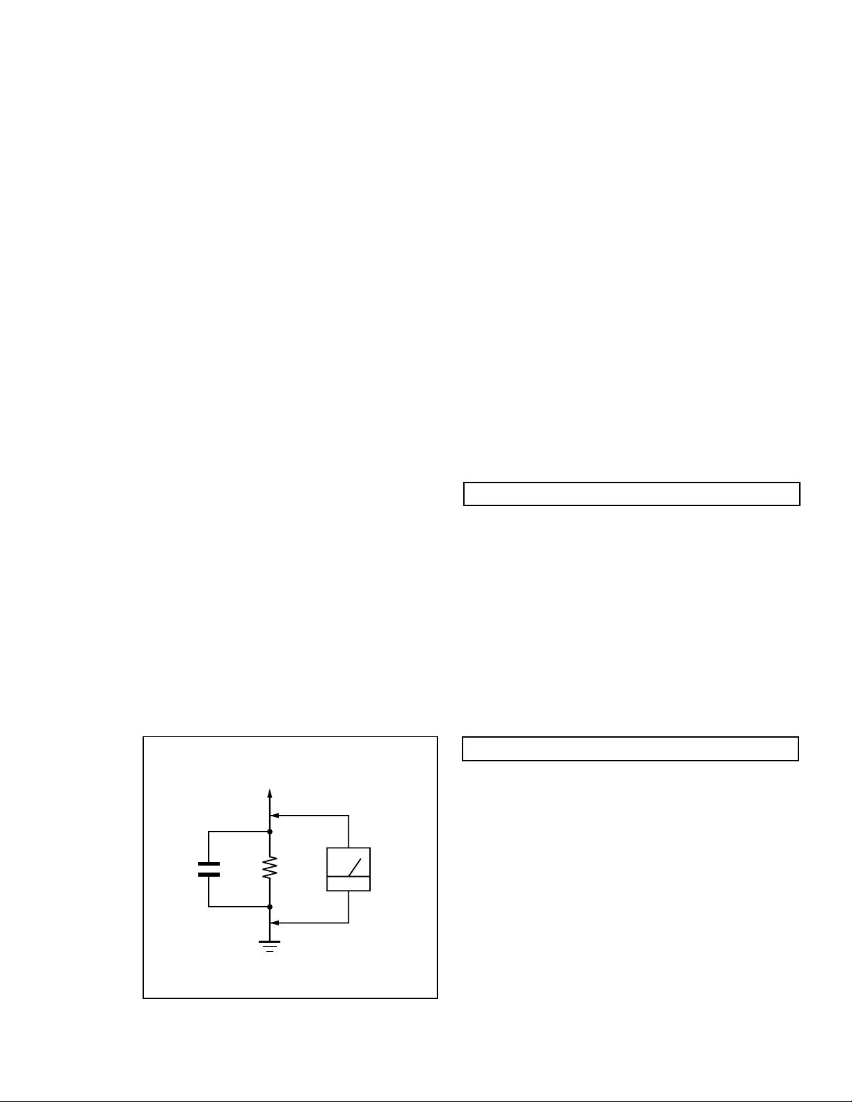
LEAKAGE TEST
The AC leakage from any exposed metal part to earth ground
and from all exposed metal parts to any exposed metal part having
a return to chassis, must not exceed 0.5 mA (500 microampere).
Leakage current can be measured by any one of three methods.
1. A commercial leakage tester, such as the Simpson 229 or
RCA WT-540A. Follow the manufacturers' instructions to
use these instructions.
2. A battery-operated AC milliammeter. The Data Precision
245 digital multimeter is suitable for this job.
3. Measuring the voltage drop across a resistor by means of
a VOM or battery-operated AC voltmeter. The "limit"
indication is 0.75 V, so analog meters must have an accurate
low voltage scale. The Simpson's 250 and Sanwa
SH-63Trd are examples of passive VOMs that are suitable.
Nearly all battery operated digital multimeters that have a
2V AC range are suitable. (See Fig. A)
WARNING!!WARNING!!
WARNING!!
WARNING!!WARNING!!
NEVER TURN ON THE POWER IN A CONDITION IN WHICH THE
DEGAUSS COIL HAS BEEN REMOVED.
SAFETY-RELATED COMPONENT WARNING!!
COMPONENTS IDENTIFIED BY SHADING AND MARK ¡ ON
THE SCHEMATIC DIAGRAMS, EXPLODED VIEWS AND IN THE
PARTS LIST ARE CRITICAL FOR SAFE OPERATION. REPLACE
THESE COMPONENTS WITH SONY PARTS WHOSE PART
NUMBERS APPEAR AS SHOWN IN THIS MANUAL OR IN
SUPPLEMENTS PUBLISHED BY SONY . CIRCUIT ADJUSTMENTS
THAT ARE CRITICAL FOR SAFE OPERATION ARE IDENTIFIED
IN THIS MANUAL. FOLLOW THESE PROCEDURES WHENEVER
CRITICAL COMPONENTS ARE REPLACED OR IMPROPER
OPERATION IS SUSPECTED.
0.15 µF
To Exposed Metal
Parts on Set
1.5 k
Earth Ground
AVERTISSEMENT!!
NE JAMAIS METTRE SOUS TENSION QUAND LA BOBINE DE
DEMAGNETISATION EST ENLEVEE.
ATTENTION AUX COMPOSANTS RELATIFS A LA
Ω
AC
Voltmeter
(0.75 V)
LES COMPOSANTS IDENTIFIES P AR UNE TRAME ET PAR UNE
MARQUE ¡ SUR LES SCHEMAS DE PRINCIPE, LES VUES
EXPLOSEES ET LES LISTES DE PIECES SONT D'UNE
IMPORTANCE CRITIQUE POUR LA SECURITE DU
FONCTIONNEMENT. NE LES REMPLACER QUE PAR DES
COMPOSANTS SONY DONT LE NUMERO DE PIECE EST
INDIQUE DANS LE PRESENT MANUEL OU D ANS DES SUPPLEMENTS PUBLIES PAR SONY. LES REGLAGES DE CIRCUIT
DONT L'IMPORTANCE EST CRITIQUE POUR LA
SECURITE DU FONCTIONNEMENT SONT IDENTIFIES DANS
LE PRESENT MANUEL. SUIVRE CES PR OCEDURES LORS DE
CHAQUE REMPLA CEMENT DE COMPOSANTS CRITIQUES, OU
LORSQU'UN MAUVAIS FONTIONNEMENT SUSPECTE
SECURITE!!
.
— 3 —

CPD-200GS
TABLE OF CONTENTS
Section Title Page
1. GENERAL ................................................................................... 5
2. DISASSEMBLY
2-1. Cabinet Removal ............................................................13
2-2. Service Position .............................................................. 13
2-3. D,A and J Board Removal.............................................. 13
2-4. Picture Tube Removal ................................................... 14
3. SAFETY RELA TED ADJUSTMENT................................. 15
4. ADJUSTMENTS ........................................................................16
5. DIAGRAMS
5-1. Block Diagram ................................................................19
5-2. Circuit Boards Location .................................................22
5-3. Schematic Diagrams and Printed Wiring Boards ...... 23
1. D Board - Schematic Diagram .................................23
2. A Board - Schematic Diagram ................................. 27
3. J Board - Schematic Diagram .................................. 30
5-4. Semiconductors ..............................................................31
6. EXPLODED VIEWS
6-1. Chassis ............................................................................ 33
6-2. Packing Materials .......................................................... 34
7. ELECTRICAL PARTS LIST ................................................ 35
— 4 —
The instructions given here are partial abstracts from the Operating Instruction
4
Getting Started
Warning on power connection
• Use an appropriate power cord for your local power
supply.
For the customers in the U.S.A.
If you do not use the appropriate cord, this monitor will
not conform to mandatory FCC standards.
Examples of plug types:
• Before disconnecting the power cord, wait at least 30
seconds after turning off the power to allow the static
electricity on the CRT display surface to discharge.
• After the power has been turned on, the CRT is
demagnetized (degaussed) for about 5 seconds. This
generates a strong magnetic field around the metal frame,
which may affect the data stored on magnetic tapes and
disks near the bezel. Place magnetic recording equipment,
tapes and disks away from this monitor.
The outlet should be installed near the equipment
and be easily accessible.
Precautions
Installation
• Prevent internal heat build-up by allowing adequate air
circulation. Do not place the monitor on surfaces (rugs,
blankets, etc.) or near materials (curtains, draperies) that
may block the ventilation holes.
• Do not install the monitor near heat sources such as
radiators or air ducts, or in a place subject to direct
sunlight, excessive dust, mechanical vibration or shock.
• Do not place the monitor near equipment which generates
magnetism, such as a transformer or high voltage power
lines.
Maintenance
• Clean the cabinet, panel and controls with a soft cloth
lightly moistened with a mild detergent solution. Do not
use any type of abrasive pad, scouring powder or solvent,
such as alcohol or benzine.
• Do not rub, touch, or tap the surface of the screen with
sharp or abrasive items such as a ballpoint pen or
screwdriver. This type of contact may result in a scratched
picture tube.
Transportation
When you transport this monitor for repair or shipment, use
the original carton and packing materials.
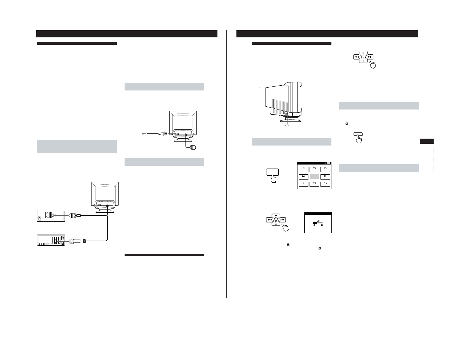
Use of the Tilt-Swivel
With the tilt-swivel, this monitor can be adjusted to the
desired angle within 180° horizontally and 20° vertically.
To turn the monitor vertically and horizontally, hold it at
the bottom with both hands as illustrated below.
for 100 to 120 V AC
for 200 to 240 V AC
Getting started
90°
90°
15°
5°
5
Getting Started
F
EN
ES
C
Getting Started
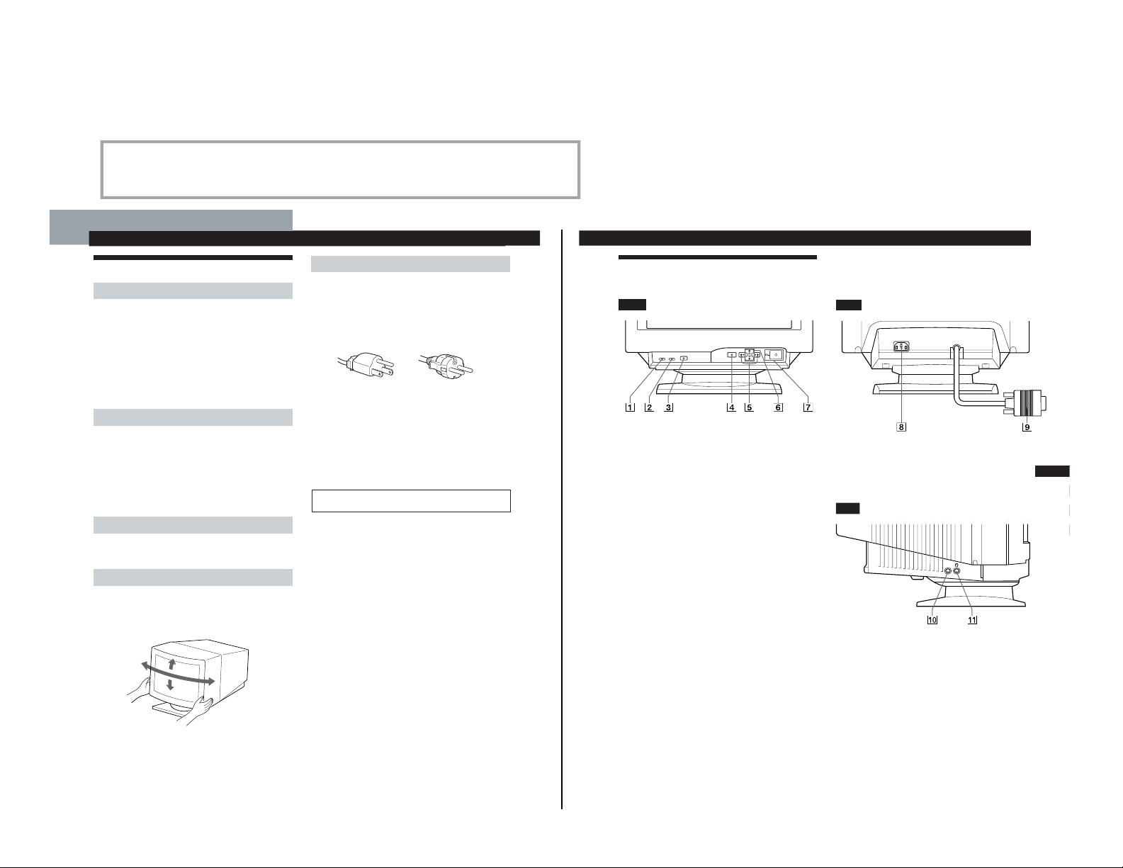
Identifying Parts and Controls
See the pages in parentheses for further details.
Front
1 MUTING button (page 7)
Mutes the sound.
2 RESET button (page 15)
Resets the adjustments to the factory settings.
3 GPE button (page 16)
Selects the Graphic Picture Enhancement (GPE) mode.
4 MENU button (pages 7 -15, 17)
Displays the MENU OSD.
5 > (contrast) (?//) buttons (pages 7 – 15,
20)
Adjust the contrast.
Function as the (?//) buttons when adjusting other
items.
6 ¨ (brightness) (./>) buttons (pages 7 –
15)
Adjust the picture brightness.
Function as the (./>) buttons when adjusting other
items.
7 u (power) switch and indicator (pages 17,
20)
Turns the monitor on or off.
The indicator lights up in green when the monitor is
turned on, and lights up in orange when the monitor is
in power saving mode.
Rear
8 AC IN connector
Provides AC power to the monitor.
9 Video input connector (HD15)
Inputs RGB video signals and SYNC signals.
Side
!º AUDIO IN jack
Inputs audio signals when connected to the computer’s
audio out jack.
!¡ 2 Headphones jack
Outputs audio signals to headphones (not supplied).
AUDIO
IN
Manual. The page numbers shown reflect those of the Operating Instruction Manual.
SECTION 1
GENERAL
— 5 —
CPD-200GS
CPD-200GS
6
Getting Started
to video output
to video output
About the supplied Macintosh adapter
The supplied Macintosh adapter is compatible with Macintosh LC,
Performa, Quadra and Power Macintosh series computers.
Macintosh II series and some older versions of Power Book models
may need an adapter with micro switches (not supplied).
Note
Do not short the pins of the video signal cable.
Step 2: Connect the power cord
With the monitor switched off, connect one end of the
power cord to the monitor and the other end to a power
outlet.
Step 3: Turn on the monitor and computer
The installation of your monitor is complete.
Note
If “OUT OF SCAN RANGE” or “NO INPUT SIGNAL” appears on
the screen, see “Warning Messages” on page 18.
For customers using Windows 95
Install the new model information from the “Windows 95 Monitor
Information Disk” into your PC. (To install the file, refer to the
attached “About the Windows 95 Monitor Information Disk/File.”)
This monitor complies with the “VESA DDC” Plug&Play standard.
If your PC/graphics board complies with DDC, select “Plug and
Play Monitor (VESA DDC)” as “Monitor type” from “Control
Panel” in Windows 95. Some PCs/graphics boards do not comply
with DDC. Even if your computer complies with DDC, it may have
some problems connecting with this monitor. In this case, select this
monitor‘s model name (CPD-100GS or CPD-200GS) as “Monitor
type” in Windows 95.
Selecting the On-screen Display
Language
If you need to change the OSD language, see “Selecting the
on-screen display language” on page 15.
The default setting is English.
to a power outlet
Power cord (supplied)
Macintosh adapter
(supplied)
IBM PC/AT or
compatible computer
Macintosh or
compatible computer
to AC IN
Setup
Before using this monitor, check that the following items are
included in your carton:
• Monitor (1)
• Power cord (1)
• Macintosh adapter (1)
• Windows
®
95 Monitor Information Disk/File (1)
• Warranty card (1)
• These operating instructions (1)
• Audio miniplug cord (1)
This monitor works with any IBM or compatible system
equipped with VGA or greater graphics capability.
Although this monitor works with other platforms running
at horizontal frequencies between 30 and 70 kHz (CPD100GS), 30 and 85 kHz (CPD-200GS), including Macintosh
and Power Macintosh systems, a cable adapter is required.
Please consult your dealer for advice on which adapter is
suitable for your needs.
Step 1: Connect the monitor to the
computer
Connecting to an IBM PC/AT, Macintosh or
compatible computer
With the computer switched off, connect the video signal
cable to the computer’s video output.
7
Getting Started
F
EN
ES
C
Getting Started
Connecting Y our Monitor’s
Speaker
You can listen to music, sounds, and other audio files using
the speaker in your monitor.
Connect the AUDIO IN jack to the audio out jack of your
computer’s sound card using the miniplug cord (supplied).
Adjusting the sound
1
Press the MENU button.
The MENU OSD appears.
2
Press the ¨./> and >?// buttons to select “™
SOUND,” and press the MENU button again.
The SOUND OSD appears.
Note
While muting the sound, the
mark appears in the SOUND OSD
instead of the Á mark. Adjust the volume to cancel the
mark
and activate the speaker.
3
Press the >?// buttons to adjust the volume.
The OSD automatically disappears after about 30 seconds.
To close the OSD, press the MENU button again.
To reset, press the RESET button while the OSD is on.
To mute the sound
Press the MUTING button.
No sound comes from the speaker.
The
mark appears at the bottom of the screen.
To cancel, press the MUTING button again.
Using the headphones jack
You can listen to the audio signals from your computer
using headphones (not supplied). The speaker turns off
when headphones are connected to the headphones jack.
Adjust the volume using the SOUND OSD.
AUDIO
IN
AUDIO IN jack
2 Headphones jack
MENU
EXIT
CENTER
SIZE
GEOM
COLOR
SOUND
ZOOM
SCREEN
OPTION
OK
MENU
MENU
SOUND
26
MUTING
— 6 —
8
Customizing Your Monitor
Introducing the On-screen
Display System
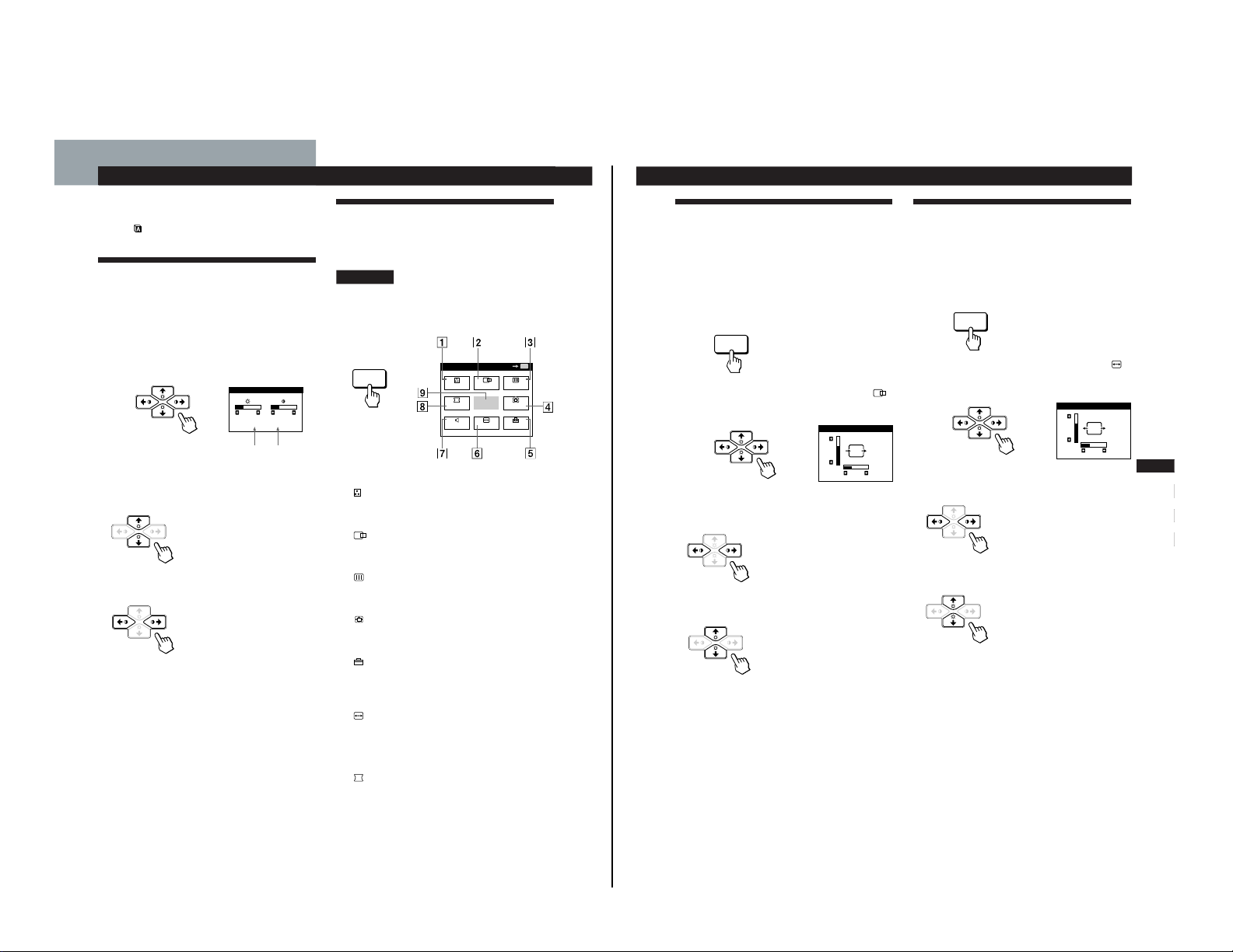
Most adjustments are made using the MENU OSD.
MENU OSD
Press the MENU button to display the MENU OSD.
This MENU OSD contains links to the other OSDs described
below.
1 COLOR
Displays the COLOR OSD for adjusting the color
temperature.
2
CENTER
Displays the CENTER OSD for adjusting the centering
of the picture.
3 SCREEN
Displays the SCREEN OSD for adjusting the vertical
and horizontal convergence, etc.
4 ZOOM
Displays the ZOOM OSD for enlarging and reducing
the picture.
5 OPTION
Displays the OPTION OSD for adjusting the OSD
position, degaussing the screen, selecting the OSD
language, etc.
6 SIZE
Displays the SIZE OSD for adjusting the picture size.
7 ™ SOUND
Displays the SOUND OSD for adjusting the sound.
8 GEOM
Displays the GEOMETRY OSD for adjusting the picture
rotation and pincushion, etc.
9 EXIT
Closes the MENU OSD.
MENU
MENU
EXIT
CENTER
SIZE
GEOM
COLOR
SOUND
ZOOM
SCREEN
OPTION
OK
MENU
Before adjusting
• Connect the monitor and the computer, and turn them on.
• Select “
(LANGUAGE)” in the OPTION OSD, then
select “ENG” (English) (see page 15).
Adjusting the Picture Brightness
and Contrast
Once the setting is adjusted , it will be stored in memory for
all input signals received.
1
Press the ¨ (brightness) ./> or > (contrast) ?//
buttons.
The BRIGHTNESS/CONTRAST OSD appears.
2
For brightness adjustment
Press the ¨./> buttons.
> . . . for more brightness
. . . . for less brightness
For contrast adjustment
Press the >?// buttons.
/ . . . for more contrast
? . . . for less contrast
The OSD automatically disappears after about 3 seconds.
To reset, press the RESET button while the OSD is on. The
brightness and contrast are both reset to the factory settings.
* The horizontal and vertical frequencies for the received input
signal appear in the BRIGHTNESS/CONTRAST OSD.
Horizontal
Frequency*
Vertical
Frequency*
Customizing Your Monitor
BRIGHTNESS/CONTRAST
26 26
60.0kHz/ 85Hz
9
Getting Started
F
EN
ES
C
Customizing Your Monitor
Using the CENTER On-screen
Display
The CENTER settings allow you to adjust the centering of
the picture.
Once the setting is adjusted, it will be stored in memory for
the current input signal.
1
Press the MENU button.
The MENU OSD appears.
2
Press the ¨./> and >?// buttons to select “
CENTER,” and press the MENU button again.
The CENTER OSD appears.
3
For horizontal adjustment
Press the >?// buttons.
/ . . . to move the picture right
? . . . to move the picture left
For vertical adjustment
Press the ¨./> buttons.
> . . . to move the picture up
. . . . to move the picture down
The OSD automatically disappears after about 30 seconds.
To close the OSD, press the MENU button again.
To reset, press the RESET button while the OSD is on.
The horizontal and vertical centerings are both reset to the
factory settings.
Using the SIZE On-screen Display
The SIZE settings allow you to adjust the size of the picture.
Once the setting is adjusted, it will be stored in memory for
the current input signal.
1
Press the MENU button.
The MENU OSD appears.
2
Press the ¨./> and >?// buttons to select “
SIZE,” and press the MENU button again.
The SIZE OSD appears.
3
For horizontal adjustment
Press the >?// buttons.
/ . . . to increase picture size
? . . . to decrease picture size
For vertical adjustment
Press the ¨./> buttons.
> . . . to increase picture size
. . . . to decrease picture size
The OSD automatically disappears after about 30 seconds.
To close the OSD, press the MENU button again.
To reset, press the RESET button while the OSD is on.
The horizontal and vertical sizes are both reset to the factory
settings.
MENU
MENU
SIZE
26
73
CENTER
26
73
— 7 —
CPD-200GS

CPD-200GS
10
Customizing Your Monitor
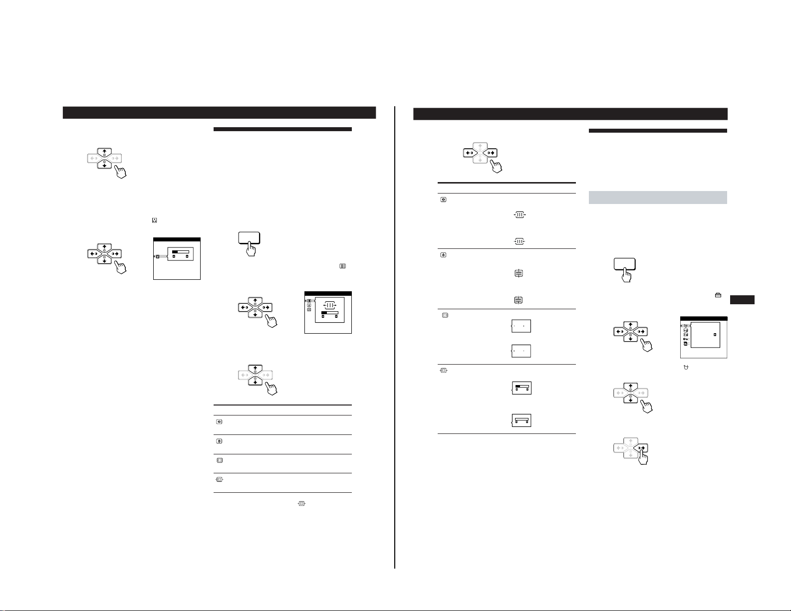
Using the GEOM (Geometry) Onscreen Display
The GEOM (geometry) settings allow you to adjust the
shape and orientation of the picture.
Once the rotation is adjusted, it will be stored in memory for
all input signals received. All other adjustments will be
stored in memory for the current input signal.
1
Press the MENU button.
The MENU OSD appears.
2
Press the ¨./> and >?// buttons to select “
GEOM,” and press the MENU button again.
The GEOMETRY OSD appears.
3
Press the ¨./> buttons to select the item you want
to adjust.
Select
ROTATION
PINCUSHION
PIN BALANCE
KEYSTONE
KEY BALANCE
To
adjust the picture rotation
adjust the picture sides
adjust the picture side balance
adjust the picture width
adjust the picture shape balance
4
Press the >?// buttons to adjust the settings.
The OSD automatically disappears after about 30 seconds.
To close the OSD, press the MENU button again.
To reset, press the RESET button while the OSD is on.
The selected item is reset to the factory setting.
For
ROTATION
PINCUSHION
PIN BALANCE
KEYSTONE
KEY BALANCE
Press
/ . . . to rotate the picture clockwise
? . . . to rotate the picture counterclockwise
/ . . . to expand the picture sides
? . . . to contract the picture sides
/ . . . to move the picture sides to the right
? . . . to move the picture sides to the left
/ . . . to increase the picture width at the
top
? . . . to decrease the picture width at the
top
/ . . . to move the top of the picture to
the right
? . . . to move the top of the picture to
the left
MENU
ROTATION
GEOMETRY
26
11
Getting Started
Customizing Your Monitor
F
EN
ES
C
Using the ZOOM On-screen
Display
The ZOOM settings allow you to enlarge or reduce the
picture.
Once the setting is adjusted, it will be stored in memory for
the current input signal.
1
Press the MENU button.
The MENU OSD appears.
2
Press the ¨./> and >?// buttons to select “
ZOOM,” and press the MENU button again.
The ZOOM OSD appears.
3
Press the >?//buttons to adjust the picture zoom.
/ . . . to enlarge the picture
? . . . to reduce the picture
The OSD automatically disappears after about 30 seconds.
To close the OSD, press the MENU button again.
To reset, press the RESET button while the OSD is on.
Note
The picture zoom adjustment will stop as soon as either the
horizontal or vertical size reaches its maximum or minimum value.
Using the COLOR On-screen
Display
You can change the monitor’s color temperature. For
example, you can change the colors of a picture on the
screen to match the actual colors of the printed picture.
Once the setting is adjusted, it will be stored in memory for
all input signals received.
1
Press the MENU button.
The MENU OSD appears.
2
Press the ¨./> and >?// buttons to select “
COLOR,” and press the MENU button again.
The COLOR OSD appears.
If you are using Graphic Picture Enhancement (GPE)
If you are in one of the GPE modes, the following
COLOR OSD appears when “
COLOR” is selected.
This OSD allows you to reduce the color temperature
from 11,000K to 9,300K. Press the >?// buttons to
adjust the color temperature.
For more information on using GPE, See “Selecting the
Graphic Picture Enhancement (GPE) Mode” on page 16.
ZOOM
73V
26H
MENU
MENU
9300K
5000K
COLOR
(continued)
COLOR
26
— 8 —
12
Customizing Your Monitor
Using the SCREEN On-screen
Display
Adjust convergence settings to eliminate red or blue
shadows that may appear around objects on the screen.
Adjust the CANCEL MOIRE function to eliminate wavy or
elliptical lines that may appear on the screen.
Once the setting is adjusted, it will be stored in memory for
all input signals received.
1
Press the MENU button.
The MENU OSD appears.
2
Press the ¨./> and >?// buttons to select “
SCREEN,” and press the MENU button again.
The SCREEN OSD appears.
3
Press the ¨./> buttons to select the item you want
to adjust.
Select
H CONVERGENCE
V CONVERGENCE
CANCEL MOIRE
*
MOIRE ADJUST
To
adjust the horizontal convergence
adjust the vertical convergence
eliminate elliptical or wavy lines on
the screen
adjust the degree of moire
cancellation
* CANCEL MOIRE must be “ON” for “
(MOIRE ADJUST)”
to appear on the screen.
MENU
3
Press the ¨./> buttons to select the color
temperature.
There are two color temperature modes in the OSD.
The preset adjustments are 9,300K and 5,000K.
Selecting your own color temperature between
9,300K and 5,000K
Press the ¨./> buttons to select “
(VARIABLE)”
and adjust by pressing the >?// buttons.
/ . . . for a higher temperature (bluish)
? . . . for a lower temperature (reddish)
The OSD automatically disappears after about 30 seconds.
To close the OSD, press the MENU button again.
To reset, press the RESET button while the OSD is on. The
selected color temperature is reset to the factory settings.
9300K
5000K
COLOR
VARIABLE
50
H CONVERGENCE
SCREEN
26
13
Getting Started
Customizing Your Monitor
F
EN
ES
C
4
Press the >?// buttons to adjust the settings.
The OSD automatically disappears after about 30 seconds.
To close the OSD, press the MENU button again.
To reset, press the RESET button while the OSD is on.
The selected item is reset to the factory setting.
For
H CONVERGENCE
V CONVERGENCE
CANCEL MOIRE
MOIRE ADJUST
Using the OPTION On-screen
Display
The OPTION OSD allows you to manually degauss the
screen and adjust settings such as the OSD position and
OSD language. It also allows you to lock the controls.
Degaussing the screen
The monitor screen is automatically degaussed
(demagnetized) when the power is turned on.
You can also manually degauss the monitor.
1
Press the MENU button.
The MENU OSD appears.
2
Press the ¨./> and >?// buttons to select “
OPTION,” and press the MENU button again.
The OPTION OSD appears.
3
Press the ¨./> buttons to select “
(MANUAL
DEGAUSS).”
4
Press the > / button.
The screen is degaussed for about 5 seconds.
If you need to degauss the screen a second time, wait for at
least 20 minutes before repeating the steps above.
The OPTION OSD automatically disappears after about 30
seconds.
To close the OSD, press the MENU button again.
MENU
ON
OFF
ON
OFF
Press
/ . . . to shift red shadows to the right
and blue shadows to the left
? . . . to shift red shadows to the left
and blue shadows to the right
/ . . . to shift red shadows up and blue
shadows down
? . . . to shift red shadows down and
blue shadows up
/ . . . to turn CANCEL MOIRE “ON”
? . . . to turn CANCEL MOIRE “OFF”
/ . . . to increase the moire cancellation
effect
? . . . to decrease the moire cancellation
effect
50
0
MANUAL DEGAUSS
OPTION
ON
— 9 —
CPD-200GS
CPD-200GS
14
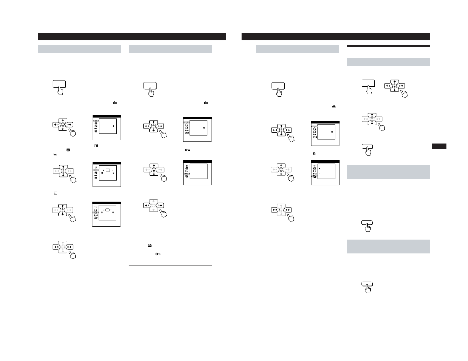
Customizing Your Monitor
Changing the on-screen display position
You can change the OSD position (for example, when you
want to adjust the picture behind the OSD).
1
Press the MENU button.
The MENU OSD appears.
2
Press the ¨./> and >?// buttons to select “
OPTION,” and press the MENU button again.
The OPTION OSD appears.
3
Press the ¨./> buttons to select “
(OSD H
POSITION)” or “
(OSD V POSITION).”
Select “
(OSD H POSITION)” to adjust the horizontal
position.
Select “
(OSD V POSITION)” to adjust the vertical
position.
4
Press the >?// buttons to move the OSD to the
desired position.
The OPTION OSD automatically disappears after about 30
seconds.
To close the OSD, press the MENU button again.
To reset, press the RESET button while the OSD is on.
MENU
Locking the controls
The control lock function disables all of the buttons on the
front panel except the u (power) switch and MENU button.
1
Press the MENU button.
The MENU OSD appears.
2
Press the ¨./> and >?// buttons to select “
OPTION,” and press the MENU button again.
The OPTION OSD appears.
3
Press the ¨./> buttons to select “
(CONTROL
LOCK).”
4
Press the >?// buttons to select “ON.”
The OPTION OSD automatically disappears after about 30
seconds.
To close the OSD, press the MENU button again.
Once you select “ON,” you cannot select any items except
“EXIT” and ”
OPTION” in the MENU OSD.
If you press any button other than the u (power) switch and
MENU button, the
mark appears on the screen.
To cancel the control lock
Repeat steps 1 through 3 above and press the >?//
buttons to select “OFF.”
MENU
OSD H POSITION
OPTION
OSD V POSITION
OPTION
CONTROL LOCK
OPTION
OFF ON
MANUAL DEGAUSS
OPTION
ON
MANUAL DEGAUSS
OPTION
ON
15
Getting Started
Customizing Your Monitor
F
EN
ES
C
Resetting the Adjustments
Resetting an adjustment item
1 Press the MENU, ¨./> and >?//buttons to select
the OSD containing the item you want to reset.
2 Press the ¨./> buttons to select the item you want
to reset.
3 Press the RESET button.
Resetting all of the adjustment data for
the current input signal
When there is no OSD displayed, press the RESET
button.
All of the adjustments data for the current input signal is
reset to the factory settings.
Note that adjustment data not affected by changes in input
signal (OSD language , OSD position and the control lock
function) is not reset to the factory settings.
Resetting all of the adjustment data for all
input signals
Press and hold the RESET button for more than two
seconds.
All of the adjustment data, including the brightness and
contrast, is reset to the factory settings.
MENU
RESET
RESET
MENU
RESET
Selecting the on-screen display language
English, French, German, Spanish and Japanese versions of
the OSDs are available.
1
Press the MENU button.
The MENU OSD appears.
2
Press the ¨./> and >?// buttons to select “
OPTION,” and press the MENU button again.
The OPTION OSD appears.
3
Press the ¨./> buttons to select “
(LANGUAGE).”
4
Press the >?// buttons to select the desired
language.
ENG: English, FRA: French, DEU: German,
ESP: Spanish, or JPN: Japanese.
The OPTION OSD automatically disappears after about 30
seconds.
To close the OSD, press the MENU button again.
To reset to English, press the RESET button while the OSD
is on.
LANGUAGE
OPTION
ENG FRA
DEU
ESP
JPN
MANUAL DEGAUSS
OPTION
ON
— 10 —
Loading...