


3-860-292-14(1)
Compact
Component
Stereo System
Operating Instructions
CMT-ED1/ED1A
©1997 by Sony Corporation
WARNING
To prevent fire or shock hazard, do not expose the unit to rain or moisture.
To avoid electrical shock, do not open the cabinet. Refer servicing to qualified personnel only.
Do not install the appliance in a confined space, such as a bookcase or built-in cabinet.
Laser component in this product is capable of emitting radiation exceeding the limit for Class 1.
This appliance is classified as a CLASS 1 LASER product. The CLASS 1 LASER PRODUCT MARKING is located on the rear exterior.
This caution label is located inside the unit.
This stereo system is equipped with the Dolby* B- type noise reduction system.
* Dolby noise reduction manufactured under license from Dolby Laboratories Licensing Corporation. “DOLBY” and the double-D symbol aare trademarks of the Dolby Laboratories Licensing Corporation.
2

Table of Contents |
|
Getting Started |
|
Step 1: Hooking up the system ............ |
4 |
Step 2: Setting the time ......................... |
7 |
Step 3: Presetting radio stations .......... |
8 |
Connecting optional AV |
|
components .................................... |
10 |
Basic Operations |
|
Playing a CD ......................................... |
12 |
Recording a CD .................................... |
14 |
Listening to the radio ........................... |
15 |
Recording from the radio .................... |
16 |
Playing a tape ........................................ |
18 |
The CD Player |
|
Using the CD display ........................... |
19 |
Playing CD tracks repeatedly ............. |
19 |
Playing CD tracks in random |
|
order ................................................ |
20 |
Programming CD tracks ..................... |
21 |
The Tape Deck |
|
Recording on a tape manually ........... |
22 |
Recording CD by specifying the track |
|
order ................................................ |
23 |
Sound Adjustment |
|
Activating the bass sound ................... |
25 |
Activating the sound effect ................. |
25 |
Other Features |
|
Falling asleep to music ........................ |
26 |
Waking up to music ............................. |
26 |
Timer-recording radio programmes.. |
28 |
Additional Information |
|
Precautions ............................................ |
30 |
Troubleshooting ................................... |
31 |
Specifications ........................................ |
33 |
Index ....................................................... |
34 |
F
ES
P
3

Getting Started
Step 1: Hooking up the system
Follow steps 1 through 5 to hook up your system using the supplied cords and accessories.
The rear cover |
Right speaker |
|
|
|
|
Left speaker |
|
||||
|
|
|
|
|
|
|
|
|
|
|
|
|
|
|
|
|
|
|
|
|
|
|
|
|
|
|
|
|
|
|
|
|
|
|
|
|
|
|
|
|
|
|
|
|
|
|
|
|
|
|
|
|
|
|
|
|
|
|
|
|
|
|
|
|
|
|
|
|
|
|
|
|
|
|
|
|
|
|
|
|
|
|
|
|
|
|
|
|
|
|
|
|
|
|
|
|
|
|
|
|
|
|
|
|
|
|
|
|
|
|
|
|
|
|
|
|
|
|
|
|
|
|
|
|
|
|
|
|
|
|
|
1Remove the rear cover. |
2Connect the speakers. |
Push in on the tabs and pull up on the cover.
1 Connect the speaker cords to the SPEAKER R jack and the SPEAKER L jack on the rear panel of the unit.
SPEAKER


 L
L
R
2 Attach the speaker cables to the clump.
4
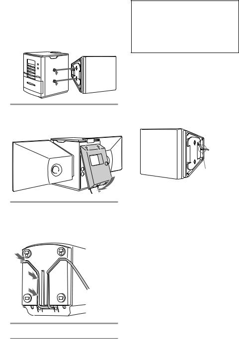
3Attach the speakers.
Facing the front of the unit, attach the speaker connected to the SPEAKER R jack onto the right side of the unit and the speaker connected to the SPEAKER L jack onto the left side of the unit.
3Reinstall the rear cover.
Put the wires through the hole at the bottom of the rear cover.
Note on the glass door of CD player
The CD player cover of the CMT-ED1 is made of tempered glass.
Under normal conditions, this tempered glass is more shock resistant and able to bear more weight than ordinary glass. This glass, however, may shatter if it receives a sharp blow or if it is scratched.
To detach the speakers
1Slide the speakers in the opposite direction of the arrows of the
illustration in “Attach the speakers” (see step 2 -3 on this page.)
2After detaching the speakers, set the speaker cords into the speaker cord groove at the bottom of the speaker. Otherwise, the speaker cord could be damaged.
Groove
4Turn the unit upside down holding the glass door with firm hand and set the speaker cord into a groove of the unit.
5Connect the mains lead to mains.
continued 5
Step 1: Hooking up the system (continued)
To remove the AM aerial
If noise is heard while listening to an AM station, remove the AM aerial from the rear panel and place the aerial outside the cabinet.
1Remove the rear cover. (See step 1 on the page 4.)
2Remove the AM aerial.
3Attach the rear cover.
(See step 3 on the page 5.)
Hook
You can hang the AM aerial on a wall. If noise is heard while listening to an FM
station, remove the FM aerial from the rear panel and place the aerial outside the cabinet.
To exchange the speaker net
You can remove the speaker net drawing up to your side and exchange with the supplied extra net.
Tip
See wire dressing for the rear panel prior to install the rear cover.
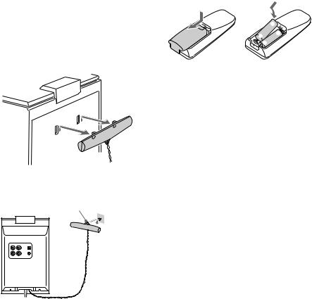
Inserting two AA (R6) batteries into the remote
]
} }

 ]
]
Tip
With normal use, the batteries should last for about six months. When the remote no longer operates the system, replace both batteries with new ones.
Note
If you do not use the remote for a long period of time, remove the batteries to avoid possible damage from battery leakage.
6
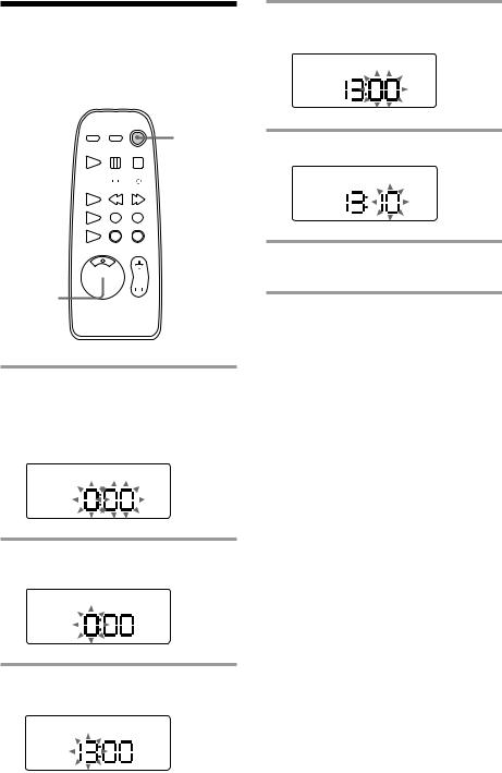
Step 2: Setting the time
4 Press ENTER.
The minute indication flashes.
You must set the time before using the timer functions.
1/u
(Power)


 3,5
3,5
1 


 2,4,6
2,4,6 

1 Press TIMER SET.
The clock of the display begins flashes. When “DAILY” or “TIMER REC” appears, press -/±repeatedly so that it disappears.
5 Press -/±to set the minutes.
6 Press ENTER.
The clock starts working.
Tip
If you make a mistake, start over from step 1.
2 Press ENTER.
The hour indication flashes.
3 Press -/±to set the hour.
The clock uses the 24 -hour system.
7

Step 3: Presetting radio stations
You can preset up to 30 stations, 20 for FM and 10 for AM.
1/u
(Power)
2
1
4,6
1/u
(Power)
2 
 4,6
4,6


 3 5
3 5 

7
1 Press FUNCTION repeatedly to select “FM” or “AM.”
2 Press FM or AM (or TUNER/BAND on the remote repeatedly).
3 Press TUNING/PLAY MODE on the remote repeatedly until “AUTO” appears.
4 Press TUNING +/– (or -/± on the remote).
The frequency indication changes and scanning stops when the system tunes in a station. “TUNED” and “ST” (for a stereo programme) appears.
PGM
TUNED ST
MHz
5 Press MEMORY on the remote.
The preset channel number flashes.
PGM
TUNED ST
MHz
6 Press TUNING +/– (or -/± on the remote) to select the preset number you want.
PGM
TUNED ST
MHz
7 Press ENTER on the remote.
The station is stored.
8 Repeat steps 4 through 7 to store other stations.
8
To tune in a station with a weak signal
Press TUNING/PLAY MODE on the remote repeatedly until “MANUAL” appears in step 3, then press TUNING +/– (or -/±on the remote) to tune in the station.
To change the preset number
Start over from step 2.
Tip
The preset stations are retained for about two days when you disconnect the mains lead or a power failure occurs.
9
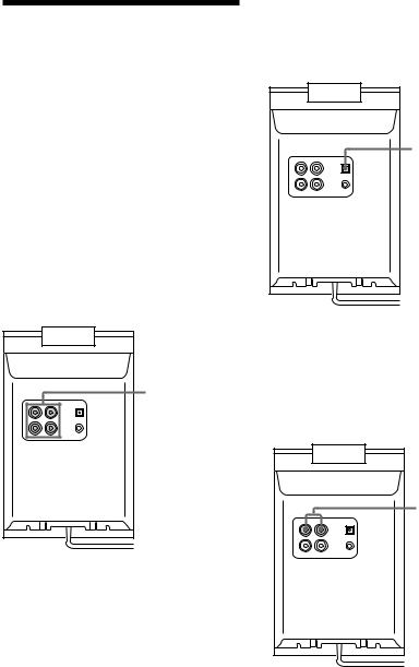
Connecting optional AV components
To enhance your system, you can connect optional components. Refer to the instructions included with each component for details.
Connecting audio components
Connecting an MD deck for analog recording
Be sure to match the colour of the plugs and the connectors. To listen to the sound from the connected MD deck, press FUNCTION repeatedly until “MD” appears.
Connecting an MD deck for digital recording
You can record from CD into the MD deck digitally by connecting an optical cable.
To the digital input of the MD deck
To the audio input/output of the MD deck
Connecting a VCR
Be sure to match the colour of the plugs and the connectors. To listen to the sound from the connected VCR, press FUNCTION repeatedly until “MD” appears.
To the audio output of the VCR
10
Connecting the headphones
Connect the headphones to the PHONES jack.
PHONES jack |
AM aerial
Connect a 6 to 15 meter insulated wire to the AM aerial terminal. Leave the supplied AM bar aerial connected.
Insulated wire |
|
(not supplied) |
AM bar aerial |
AM
Screw clamp
FM
Connecting outdoor aerials
Remove the rear cover and connect an outdoor aerial to improve the reception.
FM aerial
Connect an optional FM outdoor aerial using a 75-ohm coaxial cable and IEC standard socket connector. You can also use the TV aerial instead.
Screw clamp
AM
FM
Ground wire |
IEC standard |
(not supplied) |
socket (not |
|
supplied) |
Ground wire (not supplied)
Important
If you connect an outdoor aerial, connect a ground wire to the yterminal with the screw clamp. To prevent a gas explosion, do not connect the ground wire to a gas pipe.
11
 Loading...