


CMT-ED2U

3-867-342-13(1)
Micro HiFi
Component
System
Operating Instructions
Owner’s Record
The model and serial numbers are located on the rear of the system. Record the serial
number in the space provided below. Refer to them whenever you call upon your Sony
dealer regarding this product.
Model No.
Serial No.
CMT-ED2/ED2U
©1999 by Sony Corporation
WARNING
To prevent fire or shock hazard, do not
expose the unit to rain or moisture.
To avoid electrical shock, do not open the cabinet.
Refer servicing to qualified personnel only.
Do not install the appliance in a confined space,
such as a bookcase or built-in cabinet.
This appliance is classified as
a CLASS 1 LASER product.
The CLASS 1 LASER
PRODUCT MARKING is
located on the rear exterior.
NOTICE FOR THE CUSTOMERS IN
THE U.S.A.
This symbol is intended to alert the
user to the presence of uninsulated
“dangerous voltage” within the
product’s enclosure that may be of
sufficient magnitude to constitute a
risk of electric shock to persons.
This symbol is intended to alert the
user to the presence of important
operating and maintenance (servicing)
instructions in the literature
accompanying the appliance.
CAUTION
The use of optical instruments with this product will
increase eye hazard.
Note on CATV system installer:
This reminder is provided to call CATV system
installer’s attention to Article 820-40 of the NEC that
provides guidelines for proper grounding and, in
particular, specifies that the cable ground shall be
connected to the grounding system of the building, as
close to the point of cable entry as practical.
INFORMATION
This equipment has been tested and found to comply
with the limits for a Class B digital device, pursuant
to Part 15 of the FCC Rules. These limits are
designed to provide reasonable protection against
harmful interference in a residential installation. This
equipment generates, uses, and can radiate radio
frequency energy and, if not installed and used in
accordance with the instructions, may cause harmful
interference to radio communications. However, there
is no guarantee that interference will not occur in a
particular installation. If this equipment does cause
harmful interference to radio or television reception,
which can be determined by turning the equipment
off and on, the user is encouraged to try to correct the
interference by one or more of the following
measures:
– Reorient or relocate the receiving antenna.
– Increase the separation between the equipment and
receiver.
– Connect the equipment into an outlet on a circuit
different from that to which the receiver is
connected.
– Consult the dealer or an experienced radio/TV
technician for help.
CAUTION
You are cautioned that any changes or modification
not expressly approved in this manual could void
your authority to operate this equipment.
NOTICE FOR THE CUSTOMERS IN
CANADA
CAUTION
TO PREVENT ELECTRIC SHOCK, DO NOT USE
THIS POLARIZED AC PLUG WITH AN
EXTENSION CORD, RECEPTACLE OR OTHER
OUTLET UNLESS THE BLADES CAN BE FULLY
INSERTED TO PREVENT BLADE EXPOSURE.
This system is equipped with the Dolby* B-type noise
reduction system.
* Dolby noise reduction manufactured under license
from Dolby Laboratories Licensing Corporation.
“DOLBY” and the double-D symbol ; are
trademarks of Dolby Laboratories Licensing
Corporation.
2

Table of Contents
Getting Started
Step 1: Hooking up the system ................ 4
Step 2: Setting the time ............................ 7
Step 3:
Presetting radio stations — Preset ..
Connecting optional components ............ 10
Basic Operations
Playing a CD — Normal Play ................. 13
Recording from a CD to a tape
— CD Synchro Recording ............... 14
Listening to the radio — Preset Tuning .. 16
Recording from the radio ........................ 17
Playing a tape .......................................... 18
The CD Player
Checking the remaining playing time on the
CD .................................................... 20
Playing CD tracks repeatedly
— Repeat Play .................................. 20
Playing CD tracks in random order
— Shuffle Play ................................. 21
Playing CD tracks in a favorite order
–– Program Play ............................... 22
Sound Adjustment
Generating a more dynamic sound.......... 26
Selecting the sound mode ....................... 26
9
Other Features
Using the Radio Data System (RDS)* .... 27
Falling asleep to music — Sleep Timer .. 27
Waking up to music — Daily Timer....... 28
Timer-activated recording of radio
programs — REC Timer .................. 29
Additional Information
Precautions .............................................. 31
Troubleshooting ...................................... 32
Specifications .......................................... 34
Parts identification for the remote........... 36
Index.......................................... Back cover
* European model only
The Tape Deck
Recording to a tape manually.................. 23
Recording your favorite CD tracks to a tape
— Program Edit................................ 24
3
Getting Started
Step 1: Hooking up the system
Follow steps 1 through 6 of the procedure below to hook up your system using the supplied cords and
accessories.
The speaker grille design differs somewhat from that of the U.S. and other models.
The U.S. model is used here for illustration purposes.
Rear cover
41
1 Remove the rear cover.
U
Push in on the tabs, pull downward,
and then lift off
Right speaker
5
Left speaker
2
U
3
6
2 Connect the speakers.
1 Connect the right and left speaker cords to
the SPEAKER terminals as shown below.
3
Gray (3)
L
#
Black (#)
#
R
3
Insert this
portion
Note
Keep the speaker cords away from the
antennas to prevent noise.
4
2 Fasten the four screws to both sides of the
unit.
+
–
4 After making sure that the cords are
correctly and securely connected,
reinstall the rear cover.
Pass the speaker cords through the holes on
both sides of the rear cover.
Getting Started
3 Attach the speakers.
Facing the front of the unit, attach the
speaker connected to the SPEAKER R
terminals onto the right side of the unit
and the speaker connected to the
SPEAKER L terminals onto the left side
of the unit.
Afterwards, push down on the speakers to
make sure they are securely fastened to the
unit.
+
–
3 For models with a voltage selector, set
VOLTAGE SELECTOR to the local
power line voltage.
220-240V
110-120V
VOLTAGE SELECTOR
U
5 Turn the unit upside down while
holding the glass door firmly with your
hand, then set the speaker cord into the
groove at the bottom of the unit.
*
* This groove is used to hold the power cord
when the optional stand is attached.
continued
5
+
–
Step 1: Hooking up the system
(continued)
6 Connect the power cord to a wall outlet.
If the plug does not fit the wall socket,
detach the supplied plug adaptor (only for
models equipped with an adaptor).
Note
Do not attempt to lift up the system by the speakers.
There is a chance the unit will detach and drop. To
move the system, detach the speakers first and carry
them separately.
Note on the glass door of the CD
player
The CD player door is made of tempered glass.
Under normal conditions, this tempered glass is
more shock resistant and able to bear more weight
than ordinary glass. This glass, however, may
shatter if it receives a sharp blow or if it is
scratched.
To detach the speakers
1 Slide the speakers in the opposite direction of
the arrows of the illustration in “Attach the
speakers” (see step 2-3 on page 5).
2 After detaching the speakers, pass the speaker
cords through the speaker cord slot at the
bottom of the speaker to prevent them from
being damaged.
Tip
If you use the system with the speakers detached, you
may remove the four screws on the both sides of the
unit. If you do, be sure to retain the screws for future
use.
To replace the speaker grille
To remove the speaker grille, grasp one of the corners
and lift the grille out towards you. You can replace
the grille with one of the other supplied grilles of a
different color.
Verify which sides of the grille are rounded, then
attach the grille with the rounded sides on the top and
the bottom.
To remove the AM antenna
If noise is heard while listening to an AM station,
remove the AM antenna from the rear panel and
place the antenna outside.
1 Remove the rear cover. (see step 1 on the
page 4).
2 Remove the AM antenna.
Slot
6
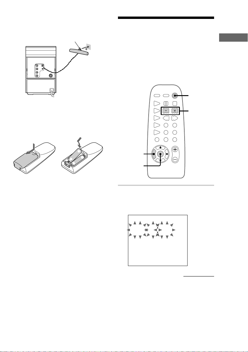
3 Reinstall the rear cover (see step 4 on the
page 5).
You can hang the AM antenna on a wall as
shown below.
If noise is heard while listening to an FM
station, remove the FM antenna from the rear
panel and place the antenna outside.
Hook
Inserting two size-AA (R6)
batteries into the remote
Step 2: Setting the time
Before you can use the system’s timer functions,
set the internal clock.
The clock uses a 24-hour system on the European
model, and a 12-hour system on other models.
The 24-hour system is used here for illustration
purposes.
To turn on the system, press ?/1.
?/1
(Power)
3,5,7
Getting Started
e
E
E
e
Tip
With normal use, the batteries should last for about
six months. When the remote no longer operates the
system, replace both batteries with new ones.
Notes on batteries
• Make sure the battery poles (plus/minus) are
properly oriented.
• Do not use a new battery with an old one.
• Do not use different types of batteries together.
• If you do not use the remote for a long period of
time, remove the batteries to prevent possible
damage from battery leakage and corrosion.
• Do not use a battery that is leaking.
• If a battery has leaked, clean the battery
compartment and replace all the batteries.
• Do not place the remote in an extremely hot or
humid place.
• Do not expose the remote sensor to direct sunlight
or lighting apparatuses. Doing so may cause a
malfunction.
1
2,4,
6,8
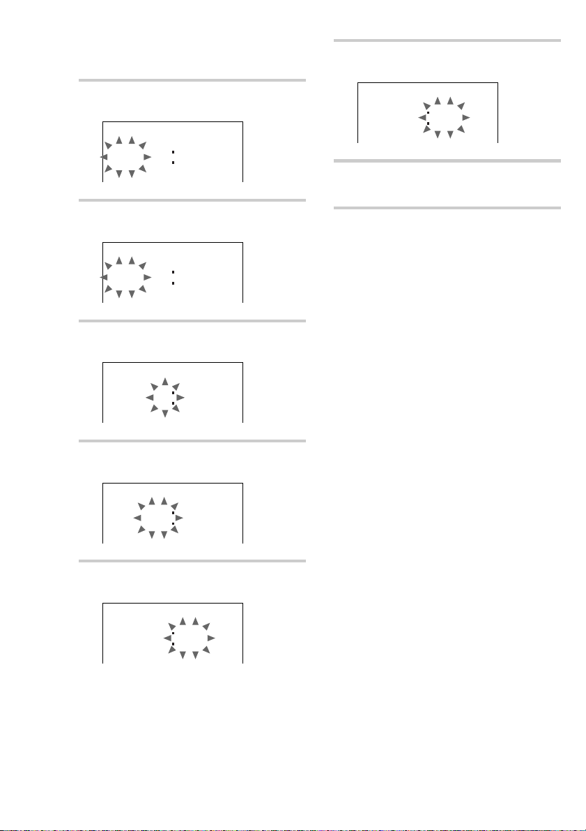
1 Press TIMER SET.
The clock on the display begins to flash.
When “DAILY” or “c REC” appears, press
l/L repeatedly until it disappears.
SU 000
continued
7
Step 2: Setting the time
(continued)
2 Press ENTER.
The day of the week indication flashes.
7 Press l/L repeatedly to set the
minute.
FR1310
SU 000
3 Press l/L repeatedly to set the
day of the week.
FR 000
4 Press ENTER.
The hour indication flashes.
FR 000
5 Press l/L repeatedly to set the
hour.
FR1300
8 Press ENTER.
The clock will begin operating.
Tip
If you make a mistake, start over from step 1.
6 Press ENTER.
The minute indication flashes.
FR1300
8
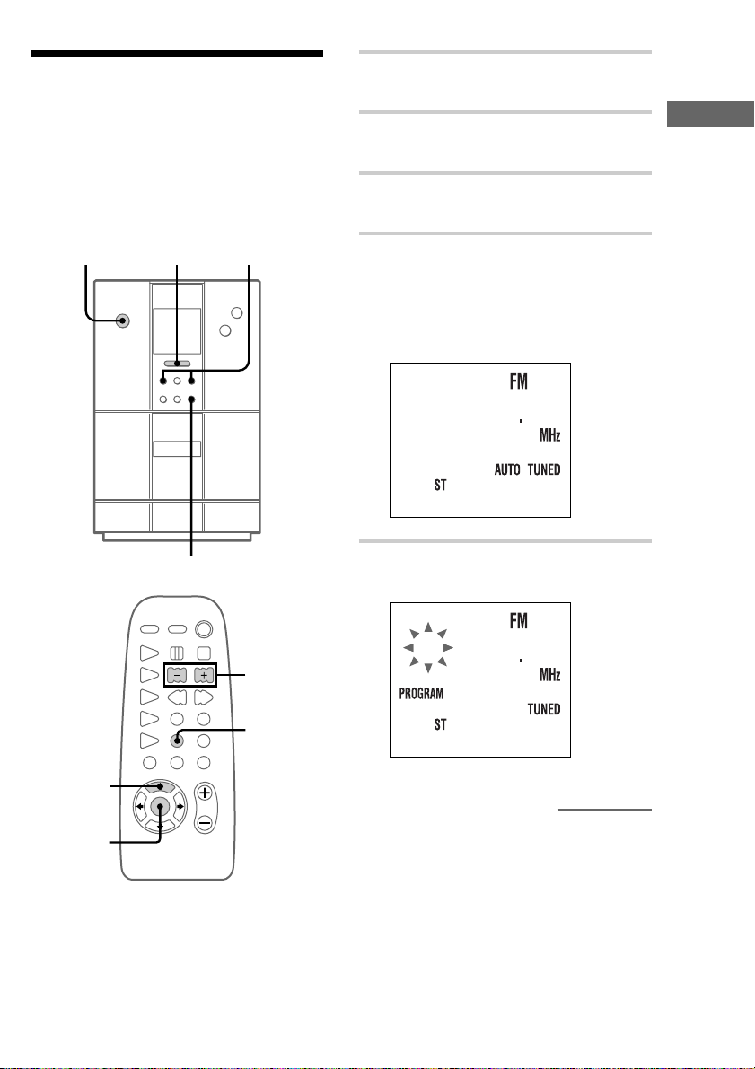
Step 3: Presetting radio
stations
The system can store a total of 30 preset stations
(20 for FM and 10 for AM). This section explains
how to tune in stations and preset them.
To turn on the system, press ?/1.
?/1
(Power)
— Preset
?/1
Z
12
+
–
nx
N
.m X M>
1 Press FUNCTION on the unit
repeatedly until “FM” or “AM” appears.
2 Press FM or AM on the unit to change
the band, if necessary.
3 Press TUNING MODE repeatedly until
“AUTO” appears.
4 Press +/–.
The frequency changes as the system scans
for a station. Scanning stops automatically
when a station is tuned in. At that time,
“TUNED” and “ST” (for stereo programs
only) appear.
1005
Getting Started
5
7
TUNING
+
5 Press MEMORY.
A preset number flashes.
1 1005
4,6
3
continued
9
Step 3: Presetting radio stations
(continued)
Connecting optional
6 Press +/– repeatedly to select the preset
number that you want.
3 1005
7 Press ENTER.
The station is stored to the selected preset
number.
8 Repeat steps 2 through 7 to preset other
stations.
To tune in a weak station
In step 3, press TUNING MODE repeatedly until
“MANUAL” appears, then press +/– repeatedly to
tune in the station.
To change the preset number
Start over from step 2.
Tip
The preset stations are saved in the system’s memory
for about two days even if you disconnect the power
cord or a power failure occurs.
components
This section explains how to connect a variety of
components to your system in order to enhance it.
Refer to the instructions included with each
component for details.
Connecting audio components
Connecting an MD deck for
analog recording
You can connect an MD deck to the system with
commercially available audio cords. Be sure to
match the color-coded pins to the appropriate
jacks. To listen to the MD deck after connecting it,
press FUNCTION repeatedly until “MD” appears.
To the audio output jacks on
the MD deck
To change the AM tuning
interval (not applicable on the
European model)
The AM tuning interval is factory-preset to 9 kHz (or
10 kHz on North American model). To switch the
AM tuning interval, tune in any AM station first, then
turn off the system. Pressing TUNING + on the unit
down, turn the system back on. When you change the
interval, all the AM preset stations are erased. To
change back to the original interval, repeat the same
procedure.
10
To the audio input jacks on the MD
deck
Connecting an MD deck for
digital recording
By connecting an MD deck to the system with a
commercially available optical cable, you can
make a digital recording from a CD.
To the digital input
connector on the MD deck
Connecting a VCR
You can connect a VCR to the system with a
commercially available audio cord. Be sure to
match the color-coded pins to the appropriate
jacks. To listen to the VCR after connecting it,
press FUNCTION repeatedly until “MD” appears.
Connecting headphones
Connect headphones to the PHONES jack.
Getting Started
PHONES jack
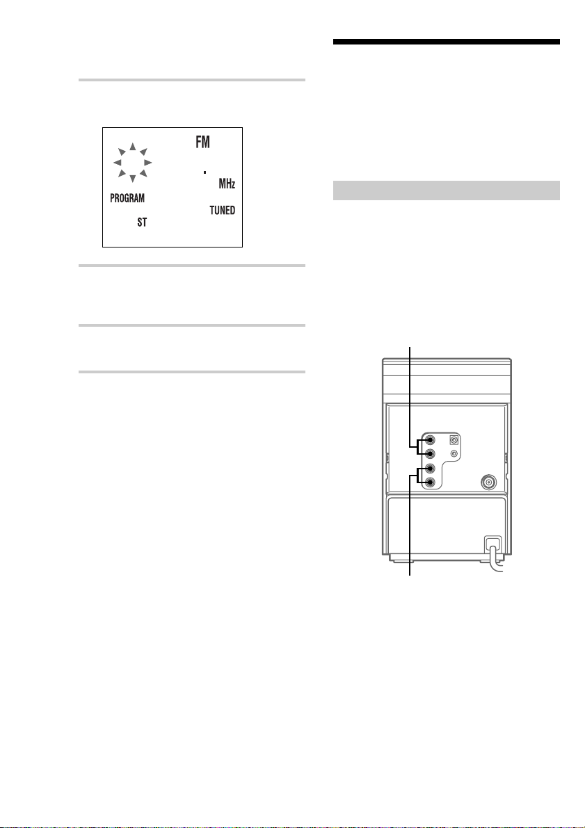
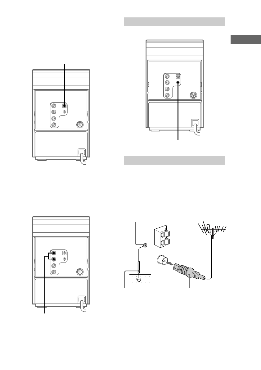
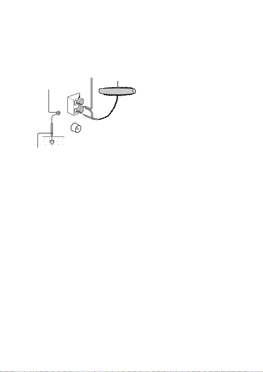
Connecting external antennas
You can connect an external antenna to your
system to get better reception.
FM antenna
Connect a commercially available external FM
antenna to the FM ANTENNA terminal as shown
below. You may also connect a TV antenna for
the same purpose.
Screw clamp
To the audio output jacks on the
VCR
U
Ground wire
(not supplied)
IEC standard
socket connector
(not supplied)
continued
11
Connecting optional components
(continued)
AM antenna
For the AM antenna, use a 6- to 15-meter (20- to
50-foot), horizontally extended insulated wire,
with one end connected to the AM ANTENNA
terminals as shown below. Leave the supplied AM
bar antenna connected.
Screw
clamp
Insulated wire
(not supplied)
AM bar antenna
U
Ground wire (not supplied)
Important
If you connect an external antenna, connect a ground
wire to the U terminal with a screw clamp. To avoid
causing a gas explosion, do not connect the ground
wire to a gas pipe.
12
 Loading...