


3-858-024-12 (1)
Trinitronâ Color Computer Display
Multiscan100sf
Multiscan200sf
Operating Instructions |
|
|
EN |
|
|
|
|
|
|
Mode d’emploi |
|
F |
||
|
|
|
||
Manual de instrucciones |
ES |
|||
|
|
|
|
|
|
|
|
|
C |
CPD-100SF
MODEL: CPD-200SF
ã 1996 by Sony Corporation

Owner’s Record
The model and serial numbers are located at the rear of the unit. Record the serial number in the space provided below. Refer to these numbers whenever you call upon your dealer regarding this product.
Model No. |
|
Serial No. |
WARNING
To prevent fire or shock hazard, do not expose the unit to rain or moisture. Dangerously high voltages are present inside the set. Do not open the cabinet. Refer servicing to qualified personnel only.
This equipment has been tested and found to comply with the limits for a Class B digital device, pursuant to Part 15 of the FCC Rules. These limits are designed to provide reasonable protection against harmful interference in a residential installation. This equipment generates, uses, and can radiate radio frequency energy and, if not installed and used in accordance with the instructions, may cause harmful interference to radio communications. However, there is no guarantee that interference will not occur in a particular installation. If this equipment does cause harmful interference to radio or television reception, which can be determined by turning the equipment off and on, the user is encouraged to try to correct the interference by one or more of the following measures:
–Reorient or relocate the receiving antenna.
–Increase the separation between the equipment and receiver.
–Connect the equipment into an outlet on a circuit different from that to which the receiver is connected.
–Consult the dealer or an experienced radio/TV technician for help. You are cautioned that any changes or modifications not expressly approved in this manual could void your authority to operate this equipment.
INFORMATION
This product complies with Swedish National Council for Metrology (MPR) standards issued in December 1990 (MPR II) for very low frequency (VLF) and extremely low frequency (ELF).
INFORMATION
Ce produit est conforme aux normes du Swedish National Council for Metrology de décembre 1990 (MPR II) en ce qui concerne les fréquences très basses (VLF) et extrêmement basses (ELF).
Hinweis
Dieses Gerät erfüllt bezüglich tieffrequenter (very low frequency) und tiefstfrequenter (extremely low frequency) Strahlung die Vorschriften des „Swedish National Council for Metrology (MPR)“ vom Dezember 1990 (MPR II).
INFORMACIÓN
Este producto cumple las normas del Consejo Nacional Sueco para Metrología (MPR) emitidas en diciembre de 1990 (MPR II) para frecuencias muy bajas (VLF) y frecuencias extremadamente bajas (ELF).
Dieses Gerät entspricht den folgenden europäischen EMVVorschriften für Betrieb in Wohngebieten, gewerblichen Gebieten und Leichtindustriegebieten.
EN55022/1994 Klasse B
EN50082-1/1992
EN60555-2/1987
Hinweise
∙Aus ergonomischen Gründen wird empfohlen, die Grundfarbe Blau nicht auf dunklem Untergrund zu verwenden (schlechte Erkennbarkeit, Augenbelastung bei zu geringem Zeichenkontrast).
∙Aus ergonomischen Gründen flimmern sollten nur Darstellungen bei Vertikalfrequenzen ab 70 Hz (ohne Zeilensprung) benutzt werden.
NOTICE
This notice is applicable for USA/Canada only.
If shipped to USA/Canada, install only a UL LISTED/CSA LABELLED power supply cord meeting the following specifications:
SPECIFICATIONS
Plug Type |
Nema-Plug 5-15p |
Cord |
Type SVT or SJT, minimum 3 × 18 |
|
AWG |
Length |
Maximum 15 feet |
Rating |
Minimum 7 A, 125 V |
NOTICE
Cette notice s’applique aux Etats-Unis et au Canada uniquement.
Si cet appareil est exporté aux Etats-Unis ou au Canada, utiliser le cordon d’alimentation portant la mention UL LISTED/CSA LABELLED et remplissant les conditions suivantes: SPECIFICATIONS
Type de fiche |
Fiche Nema 5-15 broches |
||||||||
Cordon |
Type SVT ou SJT, minimum 3 × 18 |
||||||||
|
|
|
|
|
|
AWG |
|||
Longueur |
Maximum 15 pieds |
||||||||
Tension |
Minimum 7 A, 125 V |
||||||||
|
|
|
|
|
|
|
|
|
|
|
|
|
|
|
|
|
|
|
|
|
|
|
|
|
|
|
|
|
|
|
|
|
|
|
|
|
|
|
|
This monitor is ENERGY STAR Compliant when used with a computer equipped with VESA Display Power Management Signaling (DPMS). As an International ENERGY STAR Partner, Sony Corporation has determined that this product meets the International ENERGY STAR Program for efficiency.
(VCCI
2
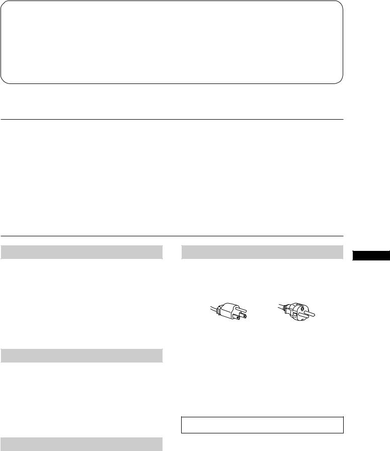
Table of Contents
Introduction .............................................................................. |
3 |
Power Saving Function |
........................................................... 8 |
Precautions ............................................................................... |
3 |
Plug and Play ........................................................................... |
8 |
Getting Started ......................................................................... |
4 |
Use of the Tilt-Swivel .............................................................. |
8 |
Using Your Monitor ................................................................ |
4 |
Damper Wire ............................................................................ |
8 |
Adjustments .............................................................................. |
5 |
Specifications ............................................................................ |
9 |
Entering New Timings ............................................................ |
8 |
Troubleshooting ..................................................................... |
10 |
Introduction
Congratulations on your purchase of a Sony Multiscan 100sf/200sf!
This monitor incorporates over 25 years of Sony experience with Trinitron display technology, ensuring excellent performance and outstanding reliability. The Multiscan 100sf/200sf’s wide scan range (Multiscan 100sf: 30 – 70 kHz, Multiscan 200sf: 30 – 80 kHz), together with Digital Multiscan Technology, allows it to sync to any video mode from standard VGA through VESA 1024 × 768 at 85 Hz, VESA 1280 × 1024 at 75 Hz (Multiscan 200sf only).
In addition, its two factory preset color modes and one user adjustable color mode give you unprecedented flexibility in matching on-screen colors to hard copy printouts.
Furthermore, the Multiscan 100sf/200sf feature digital controls, raster rotation, power saving, low emissions, and much more. All together, it delivers incredible performance with the quality and support you can expect from Sony.
Precautions
Installation
∙Prevent internal heat build-up by allowing adequate air circulation. Do not place the unit on surfaces (rugs, blankets, etc.) or near materials (curtains, draperies) that may block the ventilation holes.
∙Do not install the unit near heat sources such as radiators or air ducts, nor in a place subject to direct sunlight, excessive dust, mechanical vibration or shock.
∙Do not place the unit near equipment which generates magnetism, such as a converter or high voltage power lines.
Maintenance
∙Clean the cabinet, glass panel and controls with a soft cloth lightly moistened with a mild detergent solution. Do not use any type of abrasive pad, scouring powder or solvent, such as alcohol or benzine.
∙Do not rub, touch, or tap the surface of the screen with sharp or abrasive items, like a ball point pen or a screw driver. Otherwise, this type of contact may result in a scratched picture tube.
Warning on Power Connection |
EN |
|
∙Use the supplied power cord.
For the customers in U.S.A.
If you do not do this, this monitor will not conform to mandatory FCC standards.
for 100 to 120 V AC |
for 220 to 240 V AC |
∙Before disconnecting the power cord, wait for at least
30 seconds after turning off the power switch to allow for the discharging of static electricity on the CRT display surface.
∙After the power has been turned on, the CRT is demagnetized for approximately 5 seconds. This generates a strong magnetic field around the bezel which may affect the data stored on magnetic tape or disks near the bezel. Place such magnetic recording equipment and tapes/disks at a distance from this unit.
The socket-outlet shall be installed near the equipment and shall be easily accessible.
Transportation
When you transport this monitor for repairing or shipping, use the original carton box and packing materials.
3
Getting Started
Before using this monitor, please make sure that the following items are included in your package: Multiscan 100sf/200sf monitor (1), power cord (1), Macintosh adapter (1), warranty card (1) and this operating instruction manual (1).
This monitor will sync with any IBM or compatible system equipped with VGA or greater graphics capability. Although this monitor will sync to other platforms running at horizontal frequencies between 30 and 70 kHz (Multiscan 100sf), 30 and 80kHz (Multiscan 200sf), including Macintosh and Power Macintosh system, a cable adapter is required. Please consult your dealer for advice on which adapter is suitable for your needs.
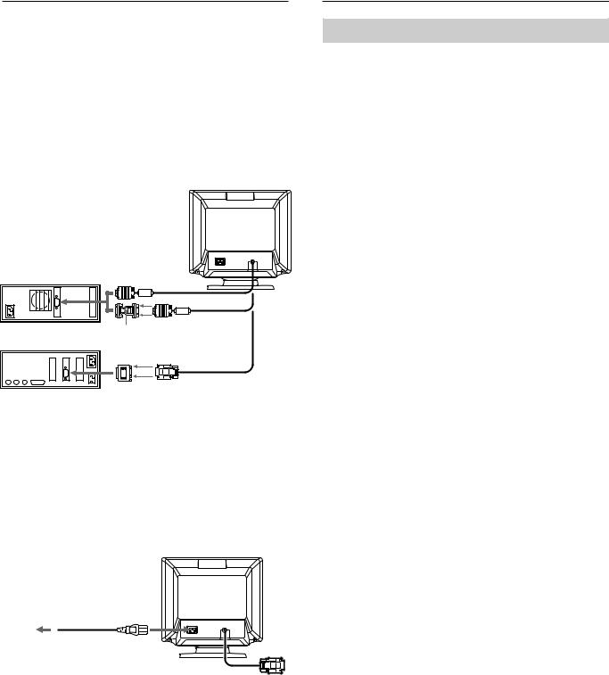
Step 1: With the computer switched off, attach the video signal cable to the video output.
IBM or compatible computer
Apple computer
to video output
HD15 - HD15 adapter
(not supplied) may be required to video output
Macintosh adapter (supplied)
Notes :
∙Use a HD15 (Female) - HD15 (Male without the No.9 pin) adapter (not supplied) for any current DOS computer which is not compatible with DDC 2 AB and its No.9 pin is disconnected.
∙Supplied Macintosh adapter is compatible with Macintosh LC, Performa, Quadra and Power Macintosh series computers. Macintosh II series and some older version of PowerBook models may need an adapter with micro switches.
Step 2: Attach the power cord to the monitor and the other end to a power outlet.
Power cord (supplied)
to a power outlet
Step 3: Turn on the monitor and computer.
Step 4: If necessary, adjust the user controls according to your personal preference.
The installation of your Multiscan 100sf/200sf is complete. Enjoy your monitor.
1)VGA is a trademark of IBM Corporation.
2)VESA is a trademark of the non-profit organization, Video Electronics Standard Association.
3)Macintosh is a trademark of Apple Computer Inc.
4)Windows® is a registered trademark of Microsoft Corporation in the United States and other countries.
Using Your Monitor
Preset and User Modes
The Multiscan 100sf/200sf has factory preset modes for the 7 most popular industry standards for true “plug and play” capability. For less common modes, the Multiscan 100sf/200sf ’s Digital Multiscan Technology will perform all of the complex adjustments necessary to ensure a high quality picture for any timing between
30 and 70Ê kHz (Multiscan 100sf ), 30 and 80Ê kHz (Multiscan 200sf ).
CPD-100SF
No. |
Resolution |
Horizontal |
Vertical |
Graphics |
|
|
(dots × lines) |
Frequency |
Frequency |
Mode |
|
|
|
|
|
|
|
1 |
640 × 480 |
31.5 kHz |
60 Hz |
VGA Graphic 1) |
|
2 |
800 × 600 |
46.9 kHz |
75 Hz |
VESA 2) |
|
3 |
800 × 600 |
53.7 kHz |
85 Hz |
VESA 2) |
|
4 |
832 × 624 |
49.7 kHz |
75 Hz |
Macintosh |
|
|
|
|
|
|
16” Color 3) |
5 |
1024 |
× 768 |
60.0 kHz |
75 Hz |
VESA 2) |
6 |
1024 |
× 768 |
68.7 kHz |
85 Hz |
VESA 2) |
7 |
1280 |
× 1024 |
64.0kHz |
60 Hz |
VESA 2) |
CPD-200SF |
|
|
|
|
|
No. |
Resolution |
Horizontal |
Vertical |
Graphics |
|
|
(dots × lines) |
Frequency |
Frequency |
Mode |
|
1 |
640 × 480 |
31.5 kHz |
60 Hz |
VGA Graphic 1) |
|
2 |
800 × 600 |
46.9 kHz |
75 Hz |
VESA 2) |
|
3 |
800 × 600 |
53.7 kHz |
85 Hz |
VESA 2) |
|
4 |
832 × 624 |
49.7 kHz |
75 Hz |
Macintosh |
|
|
|
|
|
|
16” Color 3) |
5 |
1024 |
× 768 |
60.0 kHz |
75 Hz |
VESA 2) |
6 |
1024 |
× 768 |
60.2 kHz |
75 Hz |
Macintosh |
|
|
|
|
|
19” Color 3) |
7 |
1024 |
× 768 |
68.7 kHz |
85 Hz |
VESA 2) |
8 |
1152 |
× 870 |
68.7 kHz |
75 Hz |
Macintosh |
|
|
|
|
|
21” Color 3) |
9 |
1280 |
× 1024 |
80.0 kHz |
75 Hz |
VESA 2) |
For the customers using the Windows®4)95
Install the new model information of the Sony computer display from “Windows95 Monitor Information Disk” into your PC. (To install the file, refer to the attached “About the Windows95 Monitor Information Disk/File”).
This monitor complies with “VESA DDC,” the standards of Plug&Play. If your PC/graphic board complies with DDC, select “Plug and Play Monitor (VESA DDC)” or this monitor’s model name (CPD-100SF or CPD-200SF) as “Monitor type” from “Control Panel” on Windows95. Some PC/graphic boards do not comply with DDC. Even if they comply with DDC, they may have some problems on connecting this monitor. In this case, select this monitor’s model name (CPD-100SF or CPD-200SF) as “Monitor type” on Windows95.
Recommended horizontal timing conditions
Horizontal sync width should be: >1.0 µsec.
Horizontal blanking width should be: >3.6 µsec. (Multiscan 100sf)/ >3.0 µsec. (Multiscan 200sf)
Vertical sync width should be: < 560 µsec.
Note
CPD-100SF does not apply to Macintosh 21” color mode.
4

Adjustments
When one of the preset-type signals is input, no picture adjustment is necessary.
You can, however, adjust the picture to your preferences by following the procedure described below.
You can adjust the all items on the OSD (On Screen Display).
Control Panel
pBefore adjusting the items, turn on the unit and feed the video signal from the connected computer/work station.
pAdjustments will be stored automatically.
|
|
|
|
|
POWER |
|
RESET |
COLOR |
GEOM |
SIZE |
CENTER |
SAVING |
POWER |
|
||||||
|
|
Adjusting the Picture Brightness |
|
Adjusting the Picture Centering |
The adjustment data becomes the common setting for all input signals.
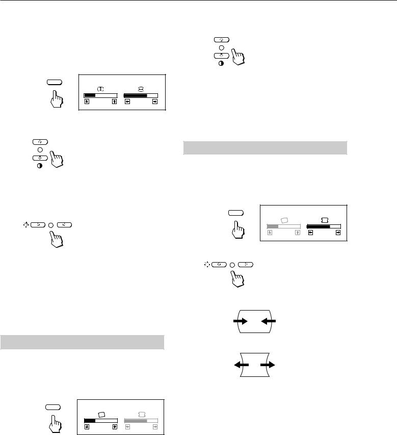
1 Press the ¬?//button.
The “CONTRAST/BRIGHTNESS” OSD appears.
The adjustment data becomes the individual setting for each input signal received.
1 Press the CENTER button. The “CENTER” OSD appears.
CONTRAST/BRIGHTNESS |
|
100 |
50 |
31.5kHz/70Hz |
|
|
2 |
Horizontal |
Vertical |
frequency |
frequency |
CENTER |
CENTER |
|
|
32 |
68 |
For vertical adjustment
Press the >>/.buttons.
2 Press the ¬?//buttons to adjust picture brightness. ?. . . for less brightness
/. . . for more brightness
The “CONTRAST/BRIGHTNESS” OSD disappears 3 seconds after you release the buttons.
To reset, press the RESET button while the OSD is on.
EN
>. . . to move up
.. . . to move down
For holizontal adjustment
Press the ¬?//buttons.
Adjusting the Picture Contrast
The adjustment data becomes the common setting for all input signals.
1 Press the >>/.button.
The “CONTRAST/BRIGHTNESS” OSD appears.
CONTRAST/BRIGHTNESS |
|
100 |
50 |
31.5kHz/70Hz |
|
Horizontal |
Vertical |
frequency |
frequency |
2 Press the >>/.buttons to adjust picture contrast. >. . . for more contrast
.. . . for less contrast
The “CONTRAST/BRIGHTNESS” OSD disappears 3 seconds after you release the buttons.
To reset, press the RESET button while the OSD is on.
?. . . to move left /. . . to move right
To erase the “CENTER” OSD, press the CENTER button again. The “CENTER” OSD automatically disappears 10 seconds after you release the buttons.
To reset, press the RESET button while the OSD is on.
The horizontal and vertical frequencies for each input signal received appear on the “CONTRAST/BRIGHTNESS” OSD.
5
Adjustments
|
2 Press the >>/.buttons. |
|
Adjusting the Picture Size |
||
>. . .to rotate clockwise |
.. . . to rotate counterclockwise
The adjustment data becomes the individual setting for each input signal received.
1 Press the SIZE button. The “SIZE” OSD appears.
SIZE |
SIZE |
|
|
32 |
68 |
2 For vertical adjustment
Press the >>/.buttons.
>. . . to enlarge
.. . . to diminish
For holizontal adjustment
Press the ¬?//buttons.
?. . . to diminish /. . . to enlarge
To erase the “SIZE” OSD, press the SIZE button again. The “SIZE” OSD automatically disappears 10 seconds after you release the buttons.
To reset, press the RESET button while the OSD is on.
To erase the “GEOMETRY” OSD, press the GEOM button again.
The “GEOMETRY” OSD automatically disappears 10 seconds after you release the buttons.
To reset, press the RESET button while the OSD is on.
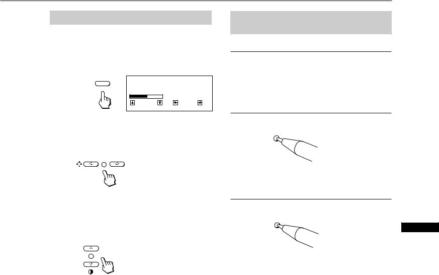
Adjusting the Pincushion
The adjustment data becomes the individual setting for each input signal received.
1 Press the GEOM button.
The “GEOMETRY” OSD appears.
GEOMETRY |
|
GEOM |
|
32 |
68 |
2 Press the ¬?//buttons.
?. . . to diminish the picture sides
Adjusting the Picture Rotation
/. . . to expand the picture sides
The adjustment data becomes the common setting for all input signals.
1 Press the GEOM button.
The “GEOMETRY” OSD appears.
GEOMETRY |
|
GEOM |
|
32 |
68 |
To erase the “GEOMETRY” OSD, press the GEOM button again.
The “GEOMETRY” OSD automatically disappears 10 seconds after you release the buttons.
To reset, press the RESET button while the OSD is on.
6
Setting the Color Temperature
The selected color temperature becomes the common setting for all input signals.
1 Press COLOR button.
The “COLOR TEMPERATURE” OSD appears.
COLOR |
COLOR TEMPERATURE |
|
VAR I ABLE |
||
|
||
|
5000K 9300K |
|
|
50 |
2 Adjust with the ¬ ?//and > >/.buttons.
To select 5000K or 9300K
Press ¬ ?//buttons.
The selected color temperature is indicated in yellow.
?. . . to select 5000K /. . . to select 9300K
To obtain the desired color temperature between 5000K and 9300K
Press > >/.buttons.
>. . . for higher temperature
.. . . for lower temperature
Your most recent adjusted color temperature will be recalled by pressing > >/.button.
To erase the “COLOR TEMPERATURE” OSD, press the COLOR button again.
The “COLOR TEMPERATURE” OSD automatically disappears 10 seconds after you release the buttons.
To reset, press the RESET button while the OSD is on.
Resetting the Adjustment Data to Factory-preset Levels
To reset an adjustment item
Press the button of the adjustment item you want to reset, and then press the RESET button before the OSD (On Screen Display) disappears.
To reset all adjustment data at once (for the received signal)
Press the RESET button with something like a pen for 1 second when no OSD is shown.
RESET
To reset all adjustment data to factorypreset levels
Press and hold the RESET button for more than 2 seconds. All adjustment data are reset to factory-preset levels.
EN
RESET
7
Entering New Timings
When using a video mode that is not one of the factory preset modes, some fine tuning may be required to optimize the display to your preferences. Simply adjust the monitor according to the preceding adjustment instructions. The adjustments will be stored automatically and recalled whenever that mode is used.
A total of 10 user-defined modes can be stored in memory. If the 11th mode is entered, it will replace the first.
Power Saving Function
This monitor meets the power saving guidelines set by the International ENERGY STAR Program as well as the more stringent TCO92 803299 (NUTEK) guidelines. It is capable of reduced power consumption when used with a computer equipped with Display Power Management Signaling (DPMS). By sensing the absence of the sync signal coming from the computer, it will reduce the power consumption as follows:
CAUTION: The Power Saving function will automatically put the monitor into Active-off state if the power switch is turned on without any video signal input. Once the horizontal and vertical syncs are sensed, the monitor will automatically return to its Normal operation state.
|
State |
Power |
Required |
u |
POWER |
|
|
resumption |
POWER |
SAVING |
|||
|
consumption |
|||||
|
|
|
time |
indicator |
indicator |
|
1 |
Normal |
100% |
— |
green on |
off |
|
operation |
||||||
|
|
|
|
|
||
|
|
|
|
|
|
|
2 |
Suspend |
approx. |
approx. |
green on |
orange on |
|
(1st step of |
||||||
10% |
3 sec. |
|||||
|
power saving) |
|
|
|||
|
|
|
|
|
||
|
|
|
|
|
|
|
|
Active-off |
|
approx. |
|
|
|
3 |
(2nd step of |
approx. 7% |
off |
orange on |
||
10 sec. |
||||||
|
power saving) |
|
|
|
||
|
|
|
|
|
||
|
|
|
|
|
|
|
4 |
Power-off |
approx. 7% |
– |
off |
off |
|
|
|
|
|
|
|
If you want the power consumption to be 0W, unplug the power cord.
Plug and Play
This monitor complies with the DDCTM1, DDC2B, DDC2AB and DDC2B+ which are the Display Data Channel (DDC) standards of VESA.
When a DDC1 host system is connected, the monitor synchronizes with the V. CLK in accordance with the VESA standards and outputs the EDID (Extended Display Identification Data) to the data line.
When a DDC2B, DDC2AB or DDC2B+ host system is connected, the monitor automatically switches to each communication.
DDCTM is a trademark of Video Electronics Standard Association.
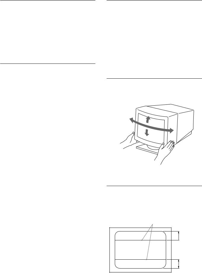
Use of the Tilt-Swivel
With the tilt-swivel, this unit can be adjusted to be viewed at your desired angle within 90˚ horizontally and 20˚ vertically. To turn the unit vertically and horizontally, hold it at its bottom with both hands.
15°
45°
45°
5°
Damper Wire
Using a white background, very thin horizontal stripes on the screen are visible as shown on the illustration. These stripes are damper wires. These wires are attached to the aperture grille inside the Trinitron tube and are there to damp vibrations of the aperture grille in order to prevent them from influencing to the picture quality.
Damper wire
Approx. 6 cm (CPD-200SF  only)
only)
Approx. 6 cm
8
Specifications
CPD-100SF
Picture tube |
0.25 mm aperture grille pitch |
|
15 inches measured diagonally |
|
90-degree deflection |
Viewable image size |
Approx. 284 × 212 mm (w/h) |
|
(11 1/4 × 8 3/8 inches) |
|
13.9” viewing image |
Logical resolution |
Horizontal: Max. 1280 dots |
|
Vertical: Max. 1024 lines |
Physical resolution |
Horizontal: Max. 1024 dots |
|
Vertical: Max. 768 lines |
Standard image area |
Approx. 270 × 202 mm (w/h) |
|
(10 3/4 × 8 inches) |
Deflection frequency |
Horizontal: 30 to 70 kHz |
|
Vertical: 50 to 120 Hz |
AC input voltage/current |
|
|
100 to 120 V, 50/60 Hz, 1.8 A |
|
220 to 240 V, 50 – 60 Hz, 1 A |
Dimensions |
Approx. 368 × 373 × 384.5 mm (w/h/d) |
|
(14 1/2 × 14 3/4 × 15 1/4 inches) |
Mass |
Approx. 14 kg (30 lb 14 oz) |
CPD-200SF |
|
|
|
Picture tube |
0.25 mm aperture grille pitch |
|
17 inches measured diagonally |
|
90-degree deflection |
Viewable image size |
Approx. 327 × 241 mm (w/h) |
|
(12 7/8 × 9 1/2 inches) |
|
15.9” viewing image |
Logical resolution |
Horizontal: Max. 1280 dots |
|
Vertical: Max. 1024 lines |
Physical resolution |
Horizontal: Max. 1280 dots |
|
Vertical: Max. 1024 lines |
Standard image area |
Approx. 312 × 234 mm (w/h) |
|
(12 3/8 × 9 1/4 inches) |
Deflection frequency |
Horizontal: 30 to 80 kHz |
|
Vertical: 50 to 120 Hz |
AC input voltage/current |
|
|
100 to 240 V, 50 – 60 Hz, 2 – 1 A |
Dimensions |
Approx. 406 × 426.5 × 451 mm (w/h/d) |
|
(16 × 16 7/8 × 17 7/8 inches) |
Mass |
Approx. 19 kg (41 lb 14 oz) |
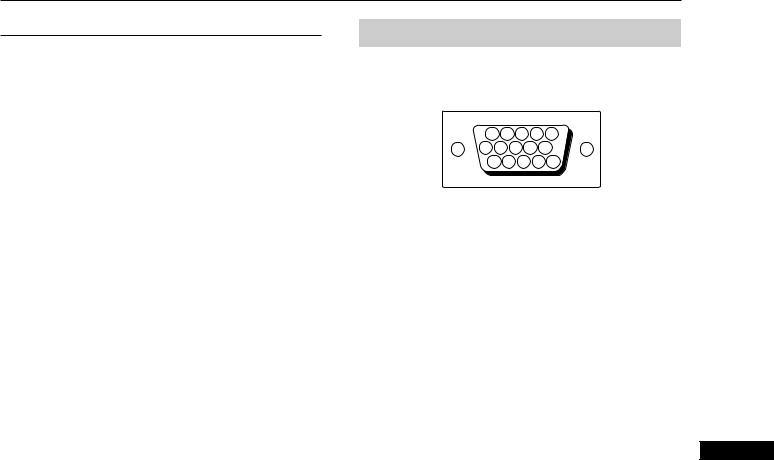
Pin assignment
Video signal cable (HD15) (Male)
The cable accepts RGB video signals (0.714 Vp-p, positive), and SYNC signals.
1 |
2 |
3 |
4 |
5 |
6 |
7 |
8 |
9 |
10 |
11 12 13 |
14 15 |
|||
Pin No. |
Signal |
Pin No. |
Signal |
|
|
|
|
|
|
1 |
Red |
8 |
Blue Ground |
|
|
|
|
|
|
2 |
Green |
9 |
DDC + 5V |
|
|
(Composite |
|
|
|
|
10 |
Ground |
||
|
Sync on Green) |
|||
|
|
|
||
|
11 |
— |
||
|
|
|||
3 |
Blue |
|
|
|
12 |
Bi-Directional |
|||
|
|
|||
4 |
— |
|
Data (SDA) |
|
|
|
|
|
|
5 |
DDC Ground |
13 |
H. Sync |
|
|
|
|
|
|
6 |
Red Ground |
14 |
V. Sync |
|
|
|
|
|
|
7 |
Green Ground |
15 |
Data Clock (SCL) |
Display Data Channel (DDC) Standard by VESA.
EN
Design and specifications are subject to change without notice.
9
 Loading...