


CDX-5V661
Table of contents
 Loading...
SERVICE MANUAL
US Model
AEP Model
CDX-5V661
/
5V661A
/
5V661D
/
5V661S
(
VW No.: 3B7 035 110/6X0 035 110/3D0 035 110/7M7 035 110
)
Photo: CDX-5V661
Ver 1.3 2001.12
Model Name Using Similar Mechanism NEW
CD Drive Mechanism Type MG-160-154
Optical Pick-up Name KSS-660C
9-873-511-14 Sony Corporation
2001L0500-1 e Vehicle Company
C 2001.12 Published by Sony Engineering Corporation
6 DISC IN-DASH CD CHANGER
Connectable head units
Manufacture Model name VW No.
SONY Gamma 1J0 035 186D
Clarion Premium 1J0 035 180D
Philips Beta 1J0 035 152B
Blaupunkt Gamma 1J0 035 186B
Blaupunkt Beta 6X0 035 152
Grundig Beta 1J0 035 152 E
Blaupunkt Radio Navigation (Color LED) 3B0 035 191 A
Blaupunkt Radio Navigation 1J0 035 191
2
CDX-5V661/5V661A/5V661D/5V661S
TABLE OF CONTENTS
1. SERVICING NOTES ................................................ 3
2. DISASSEMBLY
2-1. Disassembly Flow ........................................................... 4
2-2. Cover (Up)....................................................................... 5
2-3. Front Panel Section ......................................................... 5
2-4. Mechanism Deck (MG-160-154) ................................... 6
2-5. MAIN Board ................................................................... 7
2-6. Slide Variable Resistor
(Elevator Height Sensor) (RV1) ..................................... 8
2-7. ASSIST Board................................................................. 8
2-8. L Motor Assy (Loading) (M103).................................... 9
2-9. Chassis (TR) Main Assy ................................................. 9
2-10. Bracket (DE) Main Assy................................................. 10
2-11. Slider (TOP) Assy ........................................................... 10
2-12. Bracket (UD) Assy .......................................................... 11
2-13. Guide (Chuck) ................................................................. 11
2-14. Setting The OP Block Assy In The Highest Position ..... 12
2-15. Address Detection Flexible Board.................................. 13
2-16. Torsion Spring (OP) ........................................................ 13
2-17. OP Block Assy ................................................................ 14
3. ELECTRICAL ADJUSTMENT............................ 15
4. DIAGRAMS
4-1. Block Diagram – MAIN Section – ................................. 39
4-2. Block Diagram – DISPLAY/POWER Section – ............ 40
4-3. Note for Printed Wiring Boards and
Schematic Diagrams ....................................................... 41
4-4. Schematic Diagram – MAIN Board (1/3) – ................... 43
4-5. Schematic Diagram
– MAIN (2/3)/ASSIST/POS Boards – ........................... 44
4-6. Schematic Diagram – MAIN Board (3/3) – ................... 45
4-7. Printed Wiring Boards
– MAIN (Component Side)/ASSIST/POS Boards – ..... 46
4-8. Printed Wiring Board
– MAIN Board (Conductor Side) – ................................ 47
4-9. Printed Wiring Board – KEY Board –............................ 48
4-10. Schematic Diagram – KEY Board – .............................. 49
4-11. Printed Wiring Board – F2 Board –................................ 50
4-12. Schematic Diagram – F2 Board –................................... 51
4-13. Printed Wiring Board – F1 Board –................................ 52
4-14. Schematic Diagram – F1 Board –................................... 52
4-15. IC Pin Function Description ........................................... 57
5. EXPLODED VIEWS
5-1. Cover Section .................................................................. 60
5-2. Front Panel Section ......................................................... 61
5-3. Chassis Section ............................................................... 62
5-4. Mechanism Deck Section-1 (MG-160-154)................... 63
5-5. Mechanism Deck Section-2 (MG-160-154)................... 64
6. ELECTRICAL PARTS LIST ............................... 65
SAFETY-RELATED COMPONENT WARNING!!
COMPONENTS IDENTIFIED BY MARK 0 OR DOTTED
LINE WITH MARK 0 ON THE SCHEMATIC DIAGRAMS
AND IN THE PARTS LIST ARE CRITICAL TO SAFE
OPERATION. REPLACE THESE COMPONENTS WITH
SONY PARTS WHOSE PART NUMBERS APPEAR AS
SHOWN IN THIS MANUAL OR IN SUPPLEMENTS PUB-
LISHED BY SONY.
The laser diode in the optical pick-up block may suffer electro-
static break-down because of the potential difference generated
by the charged electrostatic load, etc. on clothing and the human
body.
During repair, pay attention to electrostatic break-down and also
use the procedure in the printed matter which is included in the
repair parts.
The flexible board is easily damaged and should be handled with
care.
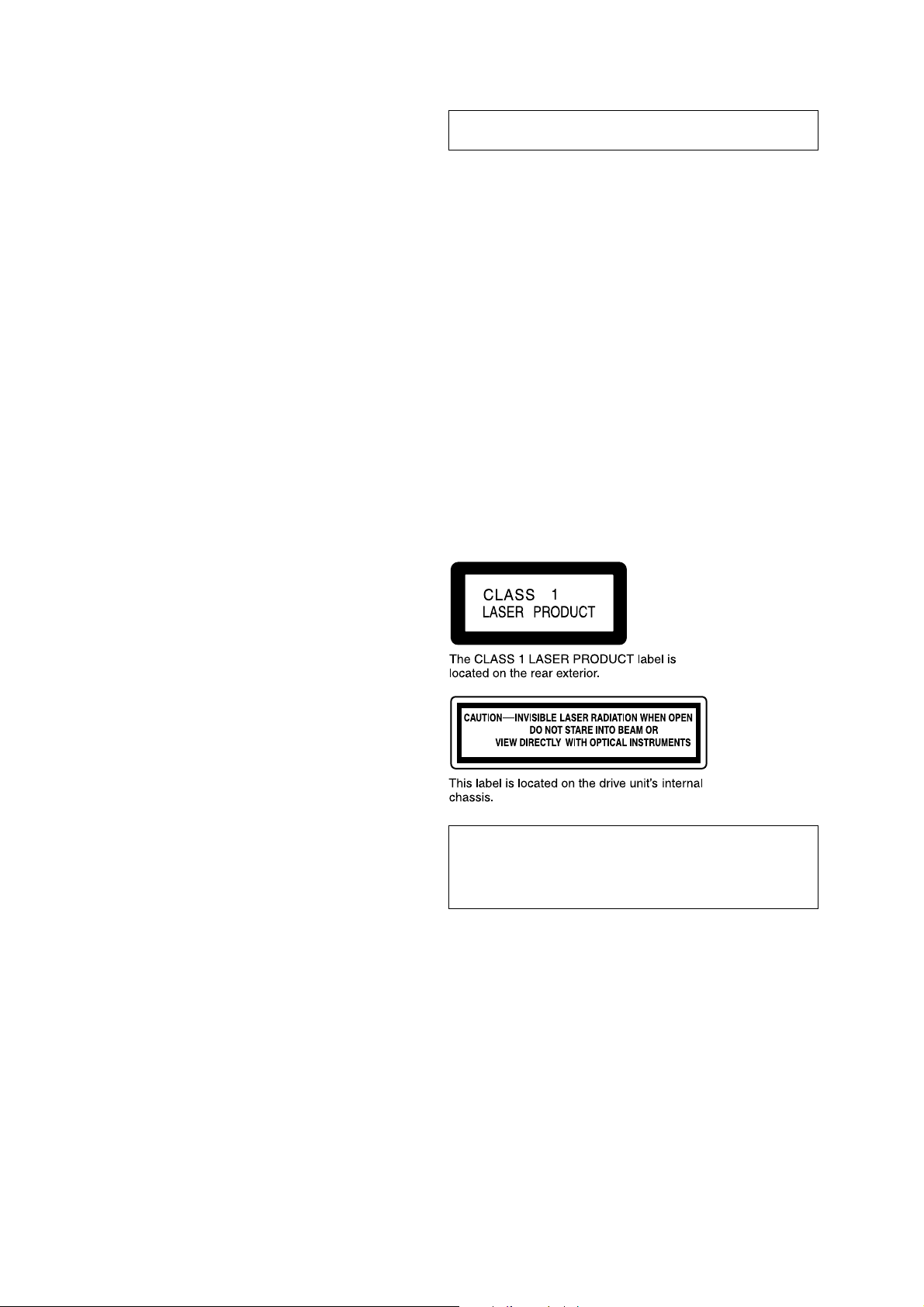
Laser Diode Properties
• Material: GaAlAs
• Wavelength: 780 nm
• Emission Duration: continuous
• Laser Output Power: less than 44.6 µW*
* This output is the value measured at a distance of 200 mm
from the objective lens surface on the Optical Pick-up Block.
NOTES ON LASER DIODE EMISSION CHECK
The laser beam on this model is concentrated so as to be focused
on the disc reflective surface by the objective lens in the optical
pick-up block. Therefore, when checking the laser diode emis-
sion, observe from more than 30 cm away from the objectiv e lens.
NOTES ON HANDLING THE OPTICAL PICK-UP
BLOCK OR BASE UNIT
Notes on chip component replacement
• Never reuse a disconnected chip component.
• Notice that the minus side of a tantalum capacitor may be dam-
aged by heat.
Flexible Circuit Board Repairing
• Keep the temperature of the soldering iron around 270 ˚C dur-
ing repairing.
• Do not touch the soldering iron on the same conductor of the
circuit board (within 3 times).
• Be careful not to apply force on the conductor when soldering
or unsoldering.
CAUTION
Use of controls or adjustments or performance of procedures
other than those specified herein may result in hazardous ra-
diation exposure.
Ver 1.2
3
CDX-5V661/5V661A/5V661D/5V661S
SECTION 1
SERVICING NOTES
• DISCRIMINATION
VWZ3Z8A3304086: CDX-5V661
VWZ3Z8A3304011: CDX-5V661A
VWZ3Z8A3304055: CDX-5V661D
SEZ3Z8A3304006 : CDX-5V661S
• HOW TO EJECT THE DISC MANUALLY
When an electric current can be applied, eject the disc forcibly by moving each motor manually.
(See “3. Electrical Adjustment 3. Mechanism check mode” on page 26).
CDX-5V661/5V661A/5V661D/5V661S
4
SECTION 2
DISASSEMBLY
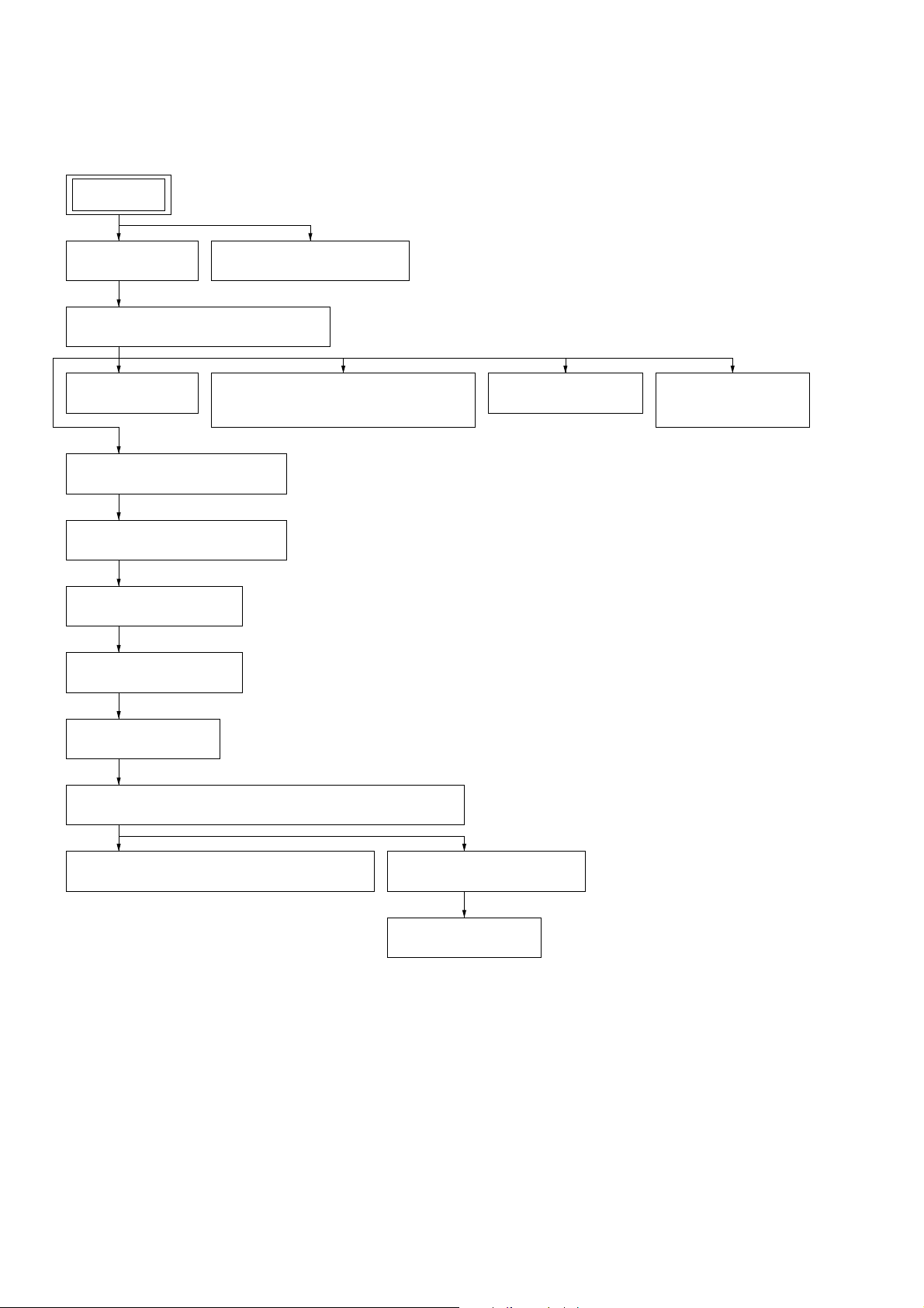
• This set can be disassembled in the order shown below.
2-1. DISASSEMBLY FLOW
2-3. FRONT PANEL SECTION
(Page 5)
2-2. COVER (UP)
(Page 5)
2-4. MECHANISM DECK (MG-160-154)
(Page 6)
2-5. MAIN BOARD
(Page 7)
2-7. ASSIST BOARD
(Page 8)
2-8. L MOTOR ASSY
(LOADING) (M103)
(Page 9)
2-9. CHASSIS (TR) MAIN ASSY
(Page 9)
2-10. BRACKET (DE) MAIN ASSY
(Page 10)
2-11. SLIDER (TOP) ASSY
(Page 10)
2-12. BRACKET (UD) ASSY
(Page 11)
2-13. GUIDE (CHUCK)
(Page 11)
2-14. SETTING THE OP BLOCK ASSY IN THE HIGHEST POSITION
(Page 12)
2-15. ADDRESS DETECTION FLEXIBLE BOARD
(Page 13)
2-16. TORSION SPRING (OP)
(Page 13)
2-17. OP BLOCK ASSY
(Page 14)
2-6. SLIDE VARIABLE RESISTOR
(ELEVATOR HEIGHT SENSOR) (RV1)
(Page 8)
SET
CDX-5V661/5V661A/5V661D/5V661S
5
Note: Follow the disassembly procedure in the numerical order given.
Note: Screws and washers cannot be re-used.
Please replace to brand-new ones once screws and washers are removed .
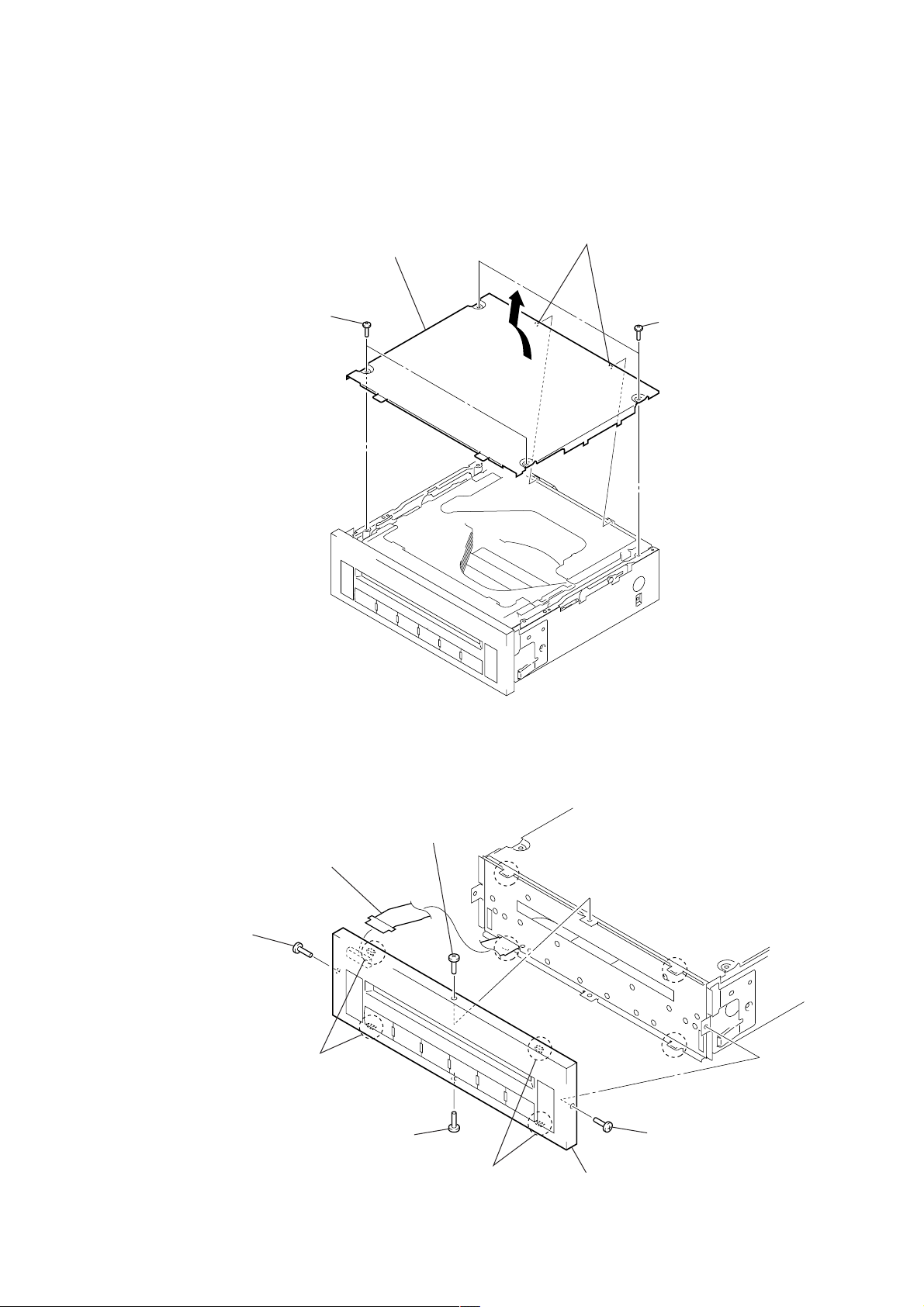
2-2. COVER (UP)
2-3. FRONT PANEL SECTION
1
two screws
(PTT2.6
×
6
)
1
two screws
(PTT2.6
×
6)
3
Remove the cover (up)
in the direction of the arrow.
2
two bosses
1
screw
(2
×
4.5)
1
screw
(2
×
4.5)
1
screw
(2
×
4.5)
1
screw
(2
×
4.5)
4
front panel section
2
two claws
2
two claws
3
key flexible board
(CN1)
CDX-5V661/5V661A/5V661D/5V661S
6
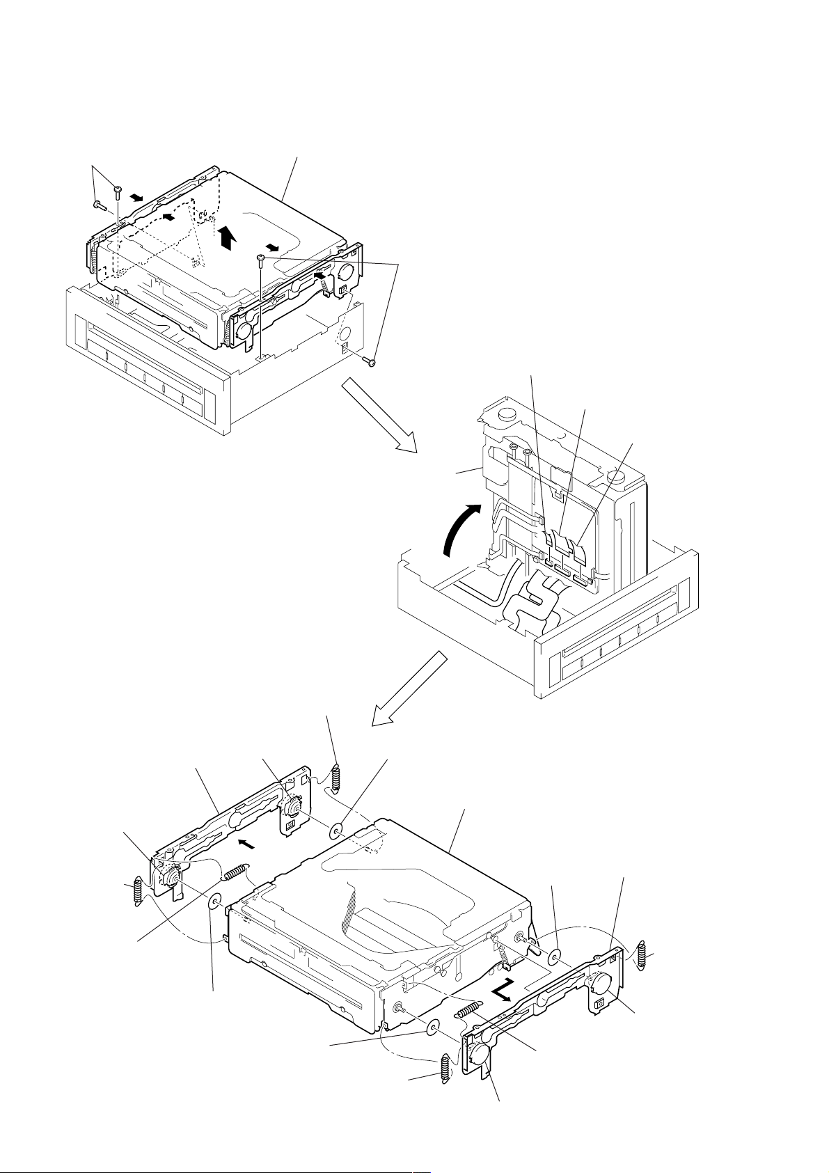
4
key flexible boar
d
(CN903)
3
Put up the mechanism
deck in the direction
of arrow
A
.
4
F2 flexible board
(CN902)
A
4
F1 flexible board
(CN901)
2-4. MECHANISM DECK (MG-160-154)
1
two screws
(PTT2.6
×
6)
1
two screws
(PTT2.6
×
6)
2
Hold the bracket (L), the bracket (R)
and the mechanism deck up
to remove from chassis assy.
5
tension coil spring (float)
7
Remove two oil dampers
from each axis, then
remove the bracket (L).
5
tension coil
spring (float)
5
tension coil
spring (float
)
5
tension coil
spring (float)
6
tension spring (float 30)
(CDX-5V661A only)
6
tension spring (float 30)
(CDX-5V661A only)
9
sheet (teflon)
9
sheet
(teflon)
9
sheet (teflon)
9
sheet (teflon)
8
Remove two oil dampers
from each axis, then
remove the bracket (R).
0
mechanism deck
(MG-160-154)
oil damper
oil damper
oil damper
oil damper

CDX-5V661/5V661A/5V661D/5V661S
7
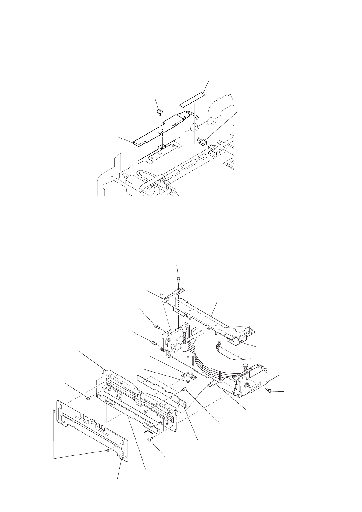
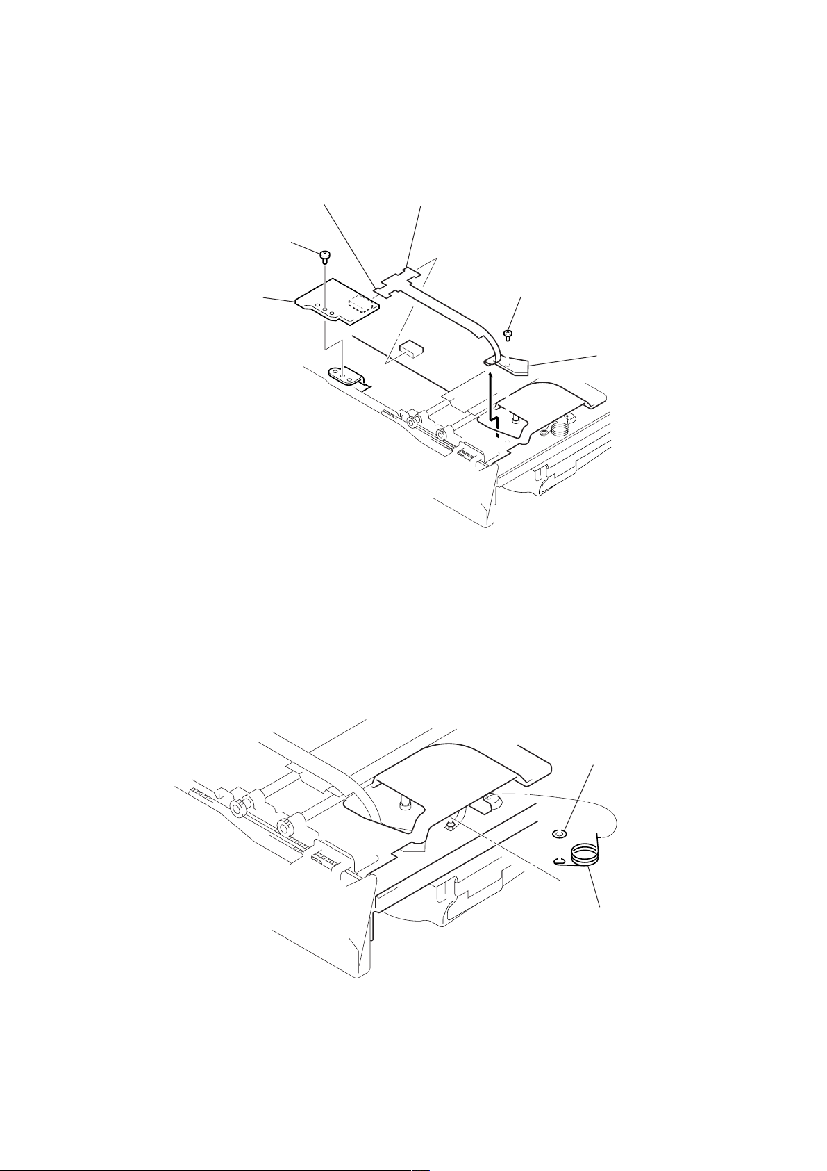
2-5. MAIN BOARD
3
assist flexible board
(CN801)
7
connector
(CN501)
7
connector
(CN503)
4
mech motor flexible board
(CN502)
1
screw (M2)
2
Disconnect the address
detection flexible board
from the connector (CN802
)
on the main board.
5
two flexible boards
(CN201, 301)
6
two cushions
(unweaved cloth)
8
three screws
(M2)
qa
main board
0
screw (M2)
9
Open the sheet (main) in th
e
direction of arrow
A
.
A
CDX-5V661/5V661A/5V661D/5V661S
8
2-6. SLIDE VARIABLE RESISTOR (ELEVATOR HEIGHT SENSOR) (RV1)
2-7. ASSIST BOARD
2
connector
(CN503)
1
cushion (unweaved cloth)
3
screw (M2)
4
slide variable resistor
(elevator height sensor)
(RV1)
4
chassis (TF) main assy
3
boss
2
screw (M2)
1
assist flexible board
(CN950)
qs
two screws
(M2)
0
two screws (M2)
0
two screws (M2)
qa
chassis (F) main assy
7
washer
8
retainer plate (DS)
0
screw (M2)
2
screw (M2)
2
four screws
(M2)
3
boss
9
lever (selection) (S)
6
shutter (A)
5
four washers (F)
qd
assist board
CDX-5V661/5V661A/5V661D/5V661S
9
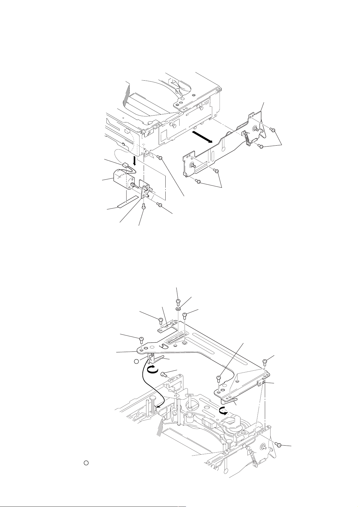
2-8. L MOTOR ASSY (LOADING) (M103)
2-9. CHASSIS (TR) MAIN ASSY
2
bracket (damper R) assy
1
two screws (M2
)
1
two screws (M2)
5
two screws (M1.7)
(P2)
8
two screws
(P2
×
2)
6
screw (M2)
9
bracket (HL) assy
3
cushion
(unweaved cloth)
0
L motor assy
(loading) (M103)
4
connector
(CN501)
7
5
screw (M2)
3
three screws
(M2)
4
screw (M1.7) (P2)
5
screw (M2)
A
4
two screws (M1.7) (P2)
1
screw (M2)
3
two screws
(M2)
4
screw (M1.7) (P2)
7
chassis (TR) main assy
Note: To install the chassis (TR) main assy,
turn the lever (EJL) and the lever (EJR) in the
direction of each arrow, hold them, and
put
a
of the lever (EJL) upon the edge pointed
by arrow
A
.
6
boss
2
washer
6
boss
lever (EJR)
lever (EJL)
a
CDX-5V661/5V661A/5V661D/5V661S
10
2-10. BRACKET (DE) MAIN ASSY
2-11. SLIDER (TOP) ASSY
2
two screws
(M2)
3
5
mech motor flexible board
6
bracket (DE) main assy
1
mech motor flexible board
(CN502)
4
Remove four solders of
mech motor flexible board.
2
two type-E stop rings 1.5
3
slider (TOP) assy
1
Slide the lever fully in the
direction of the arrow.
1
Slide the lever fully in th
e
direction of the arrow.
CDX-5V661/5V661A/5V661D/5V661S
11
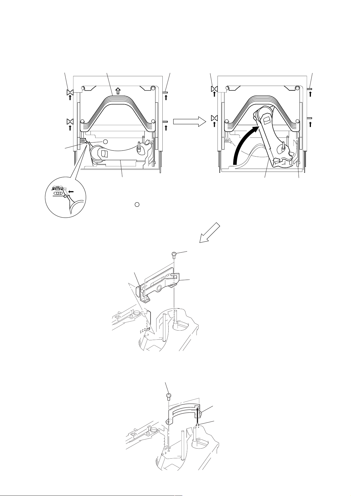
1
Slide the levers on both sides in the
direction of arrow
A
to the position
where the portion
a
of the OP block
and the lever (lock) can be disconnect.
(The tray goes up to the highest position)
Note: Do not slide the levers on both side
fully in the direction of arrow
A
in
this step.
2
Move the OP block assy in the direction of
arrow
B
. (PLAY position)
3
Slide the levers on both sides fully in the
direction of arrow
A
.
A A
A
B
A
– UP view –
a
lever lever leverlever
lever (lock)
OP block
OP block
bracket (UD) assy
tray
2-12. BRACKET (UD) ASSY
2-13. GUIDE (CHUCK)
4
two screws (M1.7)
(P2)
6
bracket (UD) assy
5
roller (UD)
1
two screws (M1.7)
(P2)
3
guide (chuck
)
2
shaft
CDX-5V661/5V661A/5V661D/5V661S
12
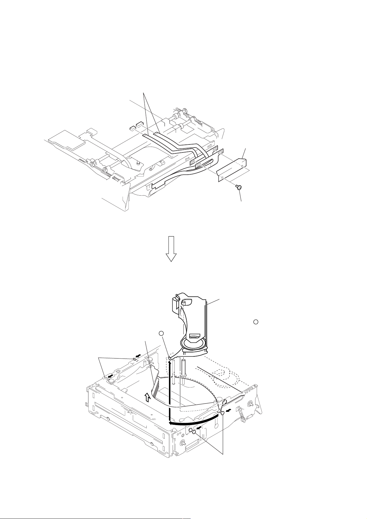
tray
1
Slide levers in the direction of
arrows until the tray goes down
to the lowest position.
1
Slide levers in the direction of
arrows until the tray goes down
to the lowest position.
OP block assy at the highest position
OP block assy at the highest position
2
Slide the lever fully in the
direction of arrow
A
.
– bottom view –
A
2-14. SETTING THE OP BLOCK ASSY IN THE HIGHEST POSITION
CDX-5V661/5V661A/5V661D/5V661S
13
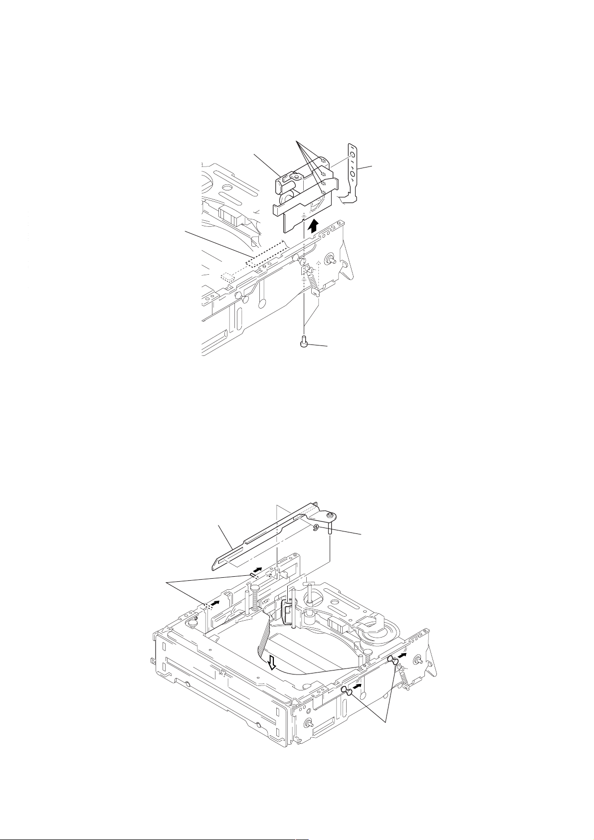
2-15. ADDRESS DETECTION FLEXIBLE BOARD
2-16. TORSION SPRING (OP)
6
POS board
3
screw (M2)
1
screw
(P1.4
×
1.4)
2
Remove the address detectio
n
flexible board in the direction
of the arrow.
5
Disconnect the address ditection flexible board
from the connector (CN960) on the POS board.
4
Disconnect the address ditection flexible board
from the connector (CN802) on the main board.
2
torsion spring (OP)
1
washer
CDX-5V661/5V661A/5V661D/5V661S
14
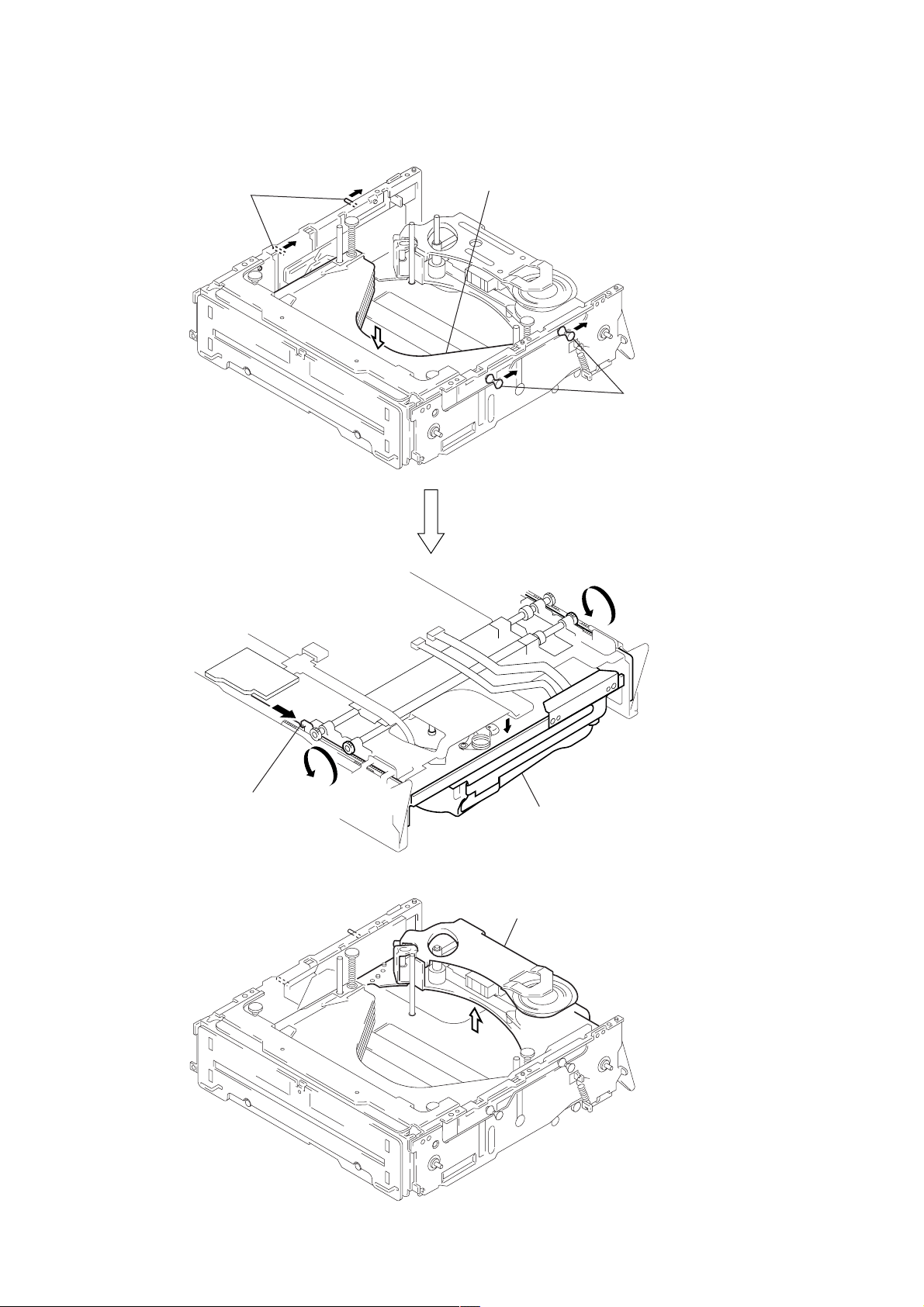
2-17. OP BLOCK ASSY
2
two screws
(special flat head M1.7)
3
cover (flexible)
1
two flexible board
(CN201, 301)
tray
4
Slide the lever fully in the
direction of arrow
A
.
4
Slide the lever fully in the
direction of arrow
A
.
A
B
A
A
A
a
5
Rotate the OP block assy in the
direction of arrow
B
.
Remove the OP block assy up
straight carefully to prevent
the portion
a
from being caugh
t
by the tray.
15
CDX-5V661/5V661A/5V661D/5V661S
SECTION 3
ELECTRICAL ADJUSTMENTS
Adjustment and Check after Repair
The execution of the following adjustment and check after repair can judge OK or NG of the Changer, or can find a faulty part from NG.
Adjustment/Check Repaired/Replaced Parts
Servo information check If optical pickup and MAIN board were replaced
(See 1. Normal Mode on page 22)
Linear position adjustment If linear position or mecha deck was repaired, or MAIN board, microcomputer (IC801)
(See 5. Production Line Mode on page 29) was replaced, or microcomputer software was up dated, or EEPROM (IC810) was re-
placed
LED adjustment If KEY board and EEPROM (IC810) were replaced
(See 6. LED Adjustment on page 31)
Jig board (SJ-5551 PANA BUS2)
This set (CDC: Changer) operates by receiving command signals from the radio through the PANA-BUS connector. The Changer cannot
operate by itself, and therefore use the jig instead of radio so as to perform the following operations:
• Normal operation
• Error code display (display/clear history)
• Aging operation
• LED luminance adjustment
• Linear position adjustment
• Servo information check
• Manual operation of mechanism motors (Elevator, Loading, Divider)
• EEPROM data reading
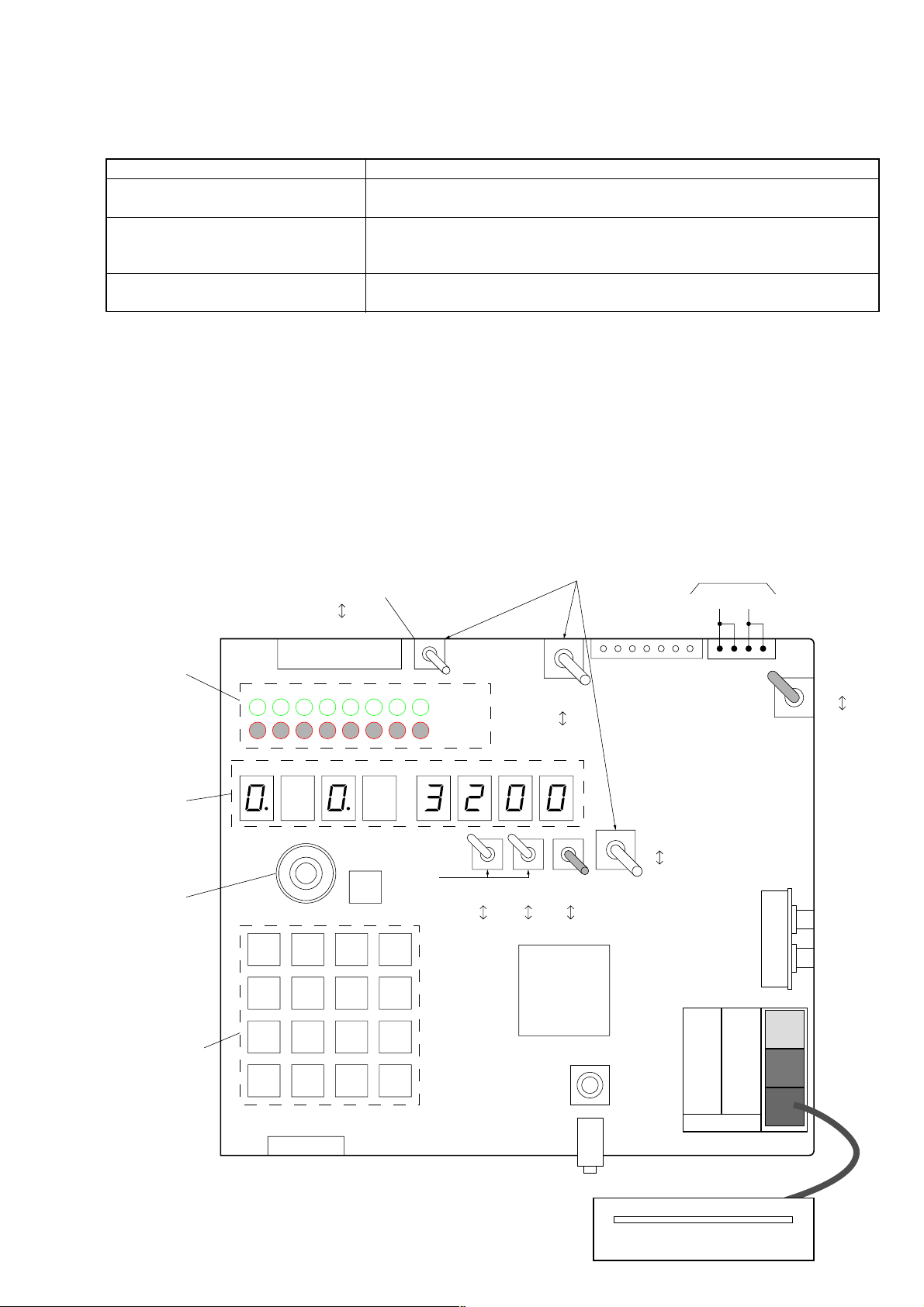
Location of switches and description of connectors
L1 L2 L3 L4 L5 L6 L7 L8
: Green
LINE
fix it down (
r
)
fix it
up (
R
)
: Red
RS-232C
uART
RST
uCOM
FL-CDC
OFF
ON
FL-JIG
OFF
ON
CTRLV
OFF
ON
H/U
RADIO
JIG
CDC
JIG
MODE LED
(for checking)
RS-232C Cable Select
STRAIGHT
CROSS
CDC Cable
connector
CDC (changer)
POWER
switch
ON
OFF
+12V GND
Push keys
(Execution keys)
SEG1 SEG2 SEG3 SEG4 SEG5 SEG6 SEG7 SEG8
1234
5678
9 101112
13 14 15 16
Power supply
Display
(7 seg. LED)
Rotary switch
(12 steps)
Jig board
(SJ-5551 PANA BUS2)
16
CDX-5V661/5V661A/5V661D/5V661S
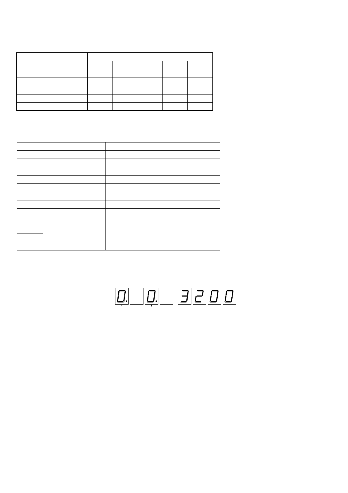
<Selection>
operation mode: rotary switch
display mode: KEY
1
, KEY
2
<Indication>
Seg. 1
Seg. 2
Seg. 3 Seg. 5 Seg. 6
Seg. 7
Seg. 8Seg. 4
LED
indication of the display mode
indication of the operation mode
(when the operation mode is 0.)
Toggle Switch Setting in Each Operation Mode
Mode
Setting of Toggle SW
LINE FL-CDC FL-JIG CTRLV H/U
CDC Flash Rewriting CDC ON OFF ON –
JIG Flash Rewriting JIG OFF ON ––
PANA-BUS Conversion Mode JIG OFF OFF ON JIG
Jig Operation Mode – OFF OFF ON JIG
MC Mode CDC OFF OFF ON JIG
Operation Modes
Each operation mode can be selected with the rotary switch.
Mode Use Description
0 Normal Operation Mode Normal operation mode
1 Special Operation Mode PANA-BUS command check mode (for design)
2 Mecha Check Mode Mechanism manual operation
3 Aging Mode Various aging modes (for design and QA)
4 Production Line Mode Aging/linear position adjustment (for line)
5 LED Check Mode LED PWM Duty adjustment
6 Diag Mode Error history check/clear
7
8
9
A
B
Selection and Indication of Operation Mode and Display Mode
17
CDX-5V661/5V661A/5V661D/5V661S
Jig Connection/Connectors
Destination Name
CDC
UART connector (for design)
PANA-BUS connector
PC RS-232C connector (for design)
H/U PANA-BUS connector (for design)
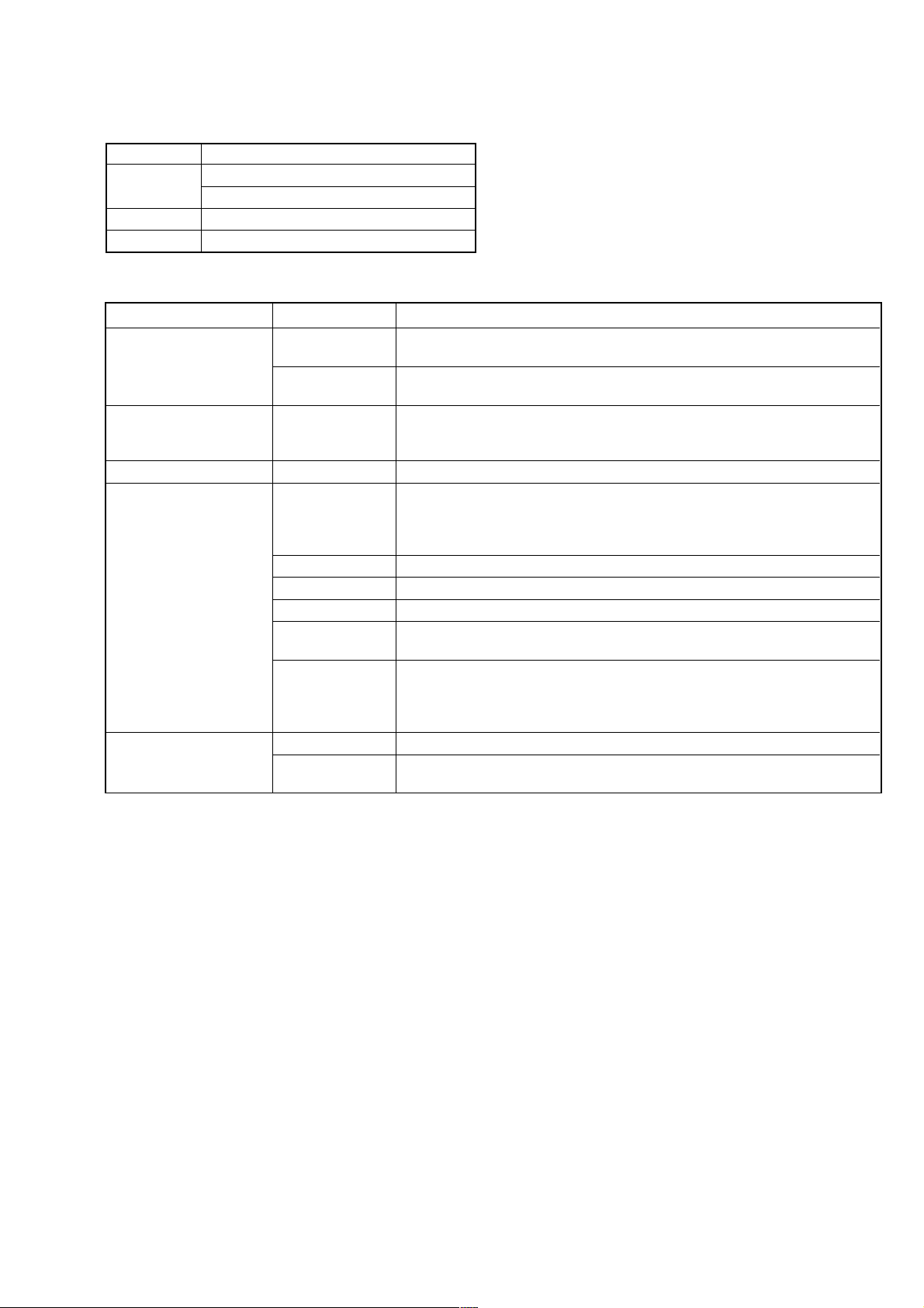
Use of Each Switch and LED on the Jig
Name Type Use
SCAN
Blink t Disc scan
MODE LED
Lit t All scan
(Number to be adjusted)
SHUFFLE
Blink t Disc shuffle
Lit t All shuffle
DTMS
Display 7 seg LED × 8 Aging count
Error
Rotary SW 12 steps Operation mode selection
UART line selection
LINE
CDC: PC y CDC
JIG: PC y JIG
FL-CDC Set CDC microcomputer to the Flash Rewrite mode.
Toggle SW FL-JIG Set Jig microcomputer to the Flash Rewrite mode.
CONTROL Control voltage
RS-232C To use str aight cable: STRAIGHT
CABLE SELECT To use cross cable: CROSS
Head Unit selection
H/U
RADIO: Radio connection mode
JIG: PANA-BUS standalone mode
Push SW
1 to16 Execution keys according to each operation mode
RST Reset key for Jig and CDC microcomputers
However, CDC cannot be reset unless the UART connector is connected.
18
CDX-5V661/5V661A/5V661D/5V661S
Display (7 Segment LED) List
Disp
Mode Description Display Format
No.
Seg. 1 Seg. 2 Seg. 3 Seg. 4 Seg. 5 Seg. 6 Seg. 7 Seg. 8
Software
0: Display Operation Version No. Version No.
Version No. Version No.
0
Version mode No. mode No. (10th place) (Unit place)
(1st decimal (2nd decimal
place) place)
Seg. 1 Seg. 2 Seg. 3 Seg. 4 Seg. 5 Seg. 6 Seg. 7 Seg. 8
1 DTMS
1: Display
Disc No.
Track No. Track No. Minute Minute Second Second
mode No. (10th place) (Unit place) (10th place) (Unit place) (10th place) (Unit place)
Seg. 1 Seg. 2 Seg. 3 Seg. 4 Seg. 5 Seg. 6 Seg. 7 Seg. 8
Servo 2: Display ESP
D-RAM D-RAM
2
Information 1 mode No. Mode
residual residual Error Rate Error Rate Error Rate Error Rate
capacity capacity
ESP MODE 0: ESP ON, 1: ESP OFF (x1), 2: ESP ON (x2)
Seg. 1 Seg. 2 Seg. 3 Seg. 4 Seg. 5 Seg. 6 Seg. 7 Seg. 8
3
Servo 3: Display Disc check Disc check
Focus Bias Focus Bias Focus Bias Focus Gain Focus Gain
Information 2 mode No. RFDC RFDC
Seg. 1 Seg. 2 Seg. 3 Seg. 4 Seg. 5 Seg. 6 Seg. 7 Seg. 8
4
Servo 4: Display
Jitter Jitter
E-F E-F E-F Tracking Tracking
Information 3 mode No. Barance Barance Barance Gain Gain
Seg. 1 Seg. 2 Seg. 3 Seg. 4 Seg. 5 Seg. 6 Seg. 7 Seg. 8
5: Display
Linear pos.
Linear pos. Linear pos.
Linear pos. Linear pos.
5 Mechanism
mode No.
adjustment
A/D value A/D value
adjusted adjusted
result value value
Linear pos. adj result 0: Not executed, 1:OK, 2: Adj required, 3: Adj & exec required, F: NG
Seg. 1 Seg. 2 Seg. 3 Seg. 4 Seg. 5 Seg. 6 Seg. 7 Seg. 8
6: Display Aging
Count
Count Count Count Count
6 Aging
mode No. mode
(10000th
(1000th place) (100th place) (10th place) (Unit place)
place)
At completion of aging, OK:PASS, NG:Exxvv (xxvv=error code)
Seg. 1 Seg. 2 Seg. 3 Seg. 4 Seg. 5 Seg. 6 Seg. 7 Seg. 8
7: Display
Linear pos.
Aging Aging Aging Aging Aging
7 Line 1
mode No.
adjustment
count count count count count
result
Linear pos. adj result 0: Not executed, 1: OK, 2: Adj required, 3:Adj & exec required, F:NG
At completion of aging, OK: PASS, NG:Exxvv (xxvv=error code)
Seg. 1 Seg. 2 Seg. 3 Seg. 4 Seg. 5 Seg. 6 Seg. 7 Seg. 8
8: Display
Type Data Data Data Data Data Data
8 Line 2 mode No.
Type 0: Serial No., 1: Model No., 2: Production Date
Serial No.: 4 digits, Model No.: 2 digits, Production Date: 6 digits
Seg. 1 Seg. 2 Seg. 3 Seg. 4 Seg. 5 Seg. 6 Seg. 7 Seg. 8
9: Display
Data Select
PWM PWM PWM PWM
mode No. (1000th place) (100th place) (10th place) (Unit place)
9
LED PWM
Adjustment
0: DIM PWM (Night Min)
1: DIM PWM (Night Max)
Data Select 2: IND PWM (Night Min)
3: IND PWM (Night Max)
4: IND PWM (Day Max)

19
CDX-5V661/5V661A/5V661D/5V661S
Disp
Mode Description Display Format
No.
Seg. 1 Seg. 2 Seg. 3 Seg. 4 Seg. 5 Seg. 6 Seg. 7 Seg. 8
A: Display
Dimmer Dimmer PWM
PWM PWM PWM
mode No.
Data select A/D value A/D value (1000th
(100th place) (10th place) (Unit place)
A
LED Data (10th place) (Unit place) place)
Display
Seg. 1 Seg. 2 Seg. 3 Seg. 4 Seg. 5 Seg. 6 Seg. 7 Seg. 8
B DIAG
B: Display
Error Error
mode No.
history history Error code Error code Error code Error code
(10th place) (Unit place)
Data select
0:DIM PWM current value
1:IND PWM current value
• The software version is displayed at the reset start or when operation mode is changed.
• Select with DISP + /– keys.
• Only the information related to the operation mode is displayed.
Error codes list
• Description of codes
xxvv xx: task where the error happened.
02 ....... Actctrl
03 ....... Servo
06 ....... Mecha
vv: Error code
e
Description Code
Sound Off Error 02 00
TOC Error 02 01
Focus Error 03 02
GFS Error 03 03
Access Error 03 04
HOT Error 03 04
Mecha Error 06 ––
Load Transition Error 06 10
Load Max Time Over 06 11
Eject Transition Error 06 20
Eject Max Time Over 06 21
Detecting Position Max Time Over 06 30
Position Av erage Error 06 31
Detecting Address Max Time Over (ST) 06 40
Address undefined Error (ST) 06 41
Home SW Error (ST) 06 42
Detecting Address Max Time Over (OP) 06 50
Address undefined Error (OP) 06 51
Home SW Error (OP) 06 52
Detecting OPP Max Time Over 06 60
Detecting OPH Max Time Over 06 70
OP lever rotated opsite and Detecting OPH Error 06 71
Error Eject Max Time Over 06 80
Load Error 06 90
Eject Give-up 06 91
Eject Give-up 06 92
Shutter Give-up 06 93
Shutter Give-up 06 94
Disc Search Give-up 06 95
Disc Search Give-up 06 96
Disc Search Give-up 06 97
Disc Search Give-up 06 98
Disc Search Give-up 06 99
Disc Search Give-up 06 9A
Disc Search Give-up 06 9B
Disc Search Give-up 06 9C
Disc Search Give-up 06 9D
• ST: Stocker is operating
OP:OP is operating (Playing)
• OPP: OP Play Position
OPH:OP Home Position

20
CDX-5V661/5V661A/5V661D/5V661S
Disc Loading Method
<To load one disc each>
Operation by buttons on changer front panel Operation by push keys on jig
1. Press
[LOAD] button. 1. Press 3 key.
2. Press the button of disc table to be loaded. 2. Press the key of disc table to be loaded (5, 6, 9, 0, qd,
qf).
3. Load a disc when the disc LED blinks fast. 3. Load a disc when the disc LED blinks fast.
<To load maximum 6 discs at a time>
Operation by buttons on changer front panel Operation by push keys on jig
1. Press
[LOAD] button for more than 3 sec. 1. Press 3 key for more than 3 sec.
2. While the disc LED is blinking, load discs in order of disc 2. While the disc LED is blinking, load discs in order of disc
table address. table address.
Disc Ejection Method
<To eject one disc each>
Operation by buttons on changer front panel Operation by push keys on jig
1. Press
[EJECT] button. 1. Press 4 key.
2. Press the button of disc table to be ejected. 2. Press the key of disc table to be ejected (5, 6, 9, 0, qd,
qf).
• To eject a disc forcibly
1. Press 4 key.
2. Press the key of disc table to be ejected (5, 6, 9, 0, qd,
qf) for more than 3 sec.
<To eject maximum 6 discs at a time>
Operation by buttons on changer front panel Operation by push keys on jig
1. Press
[EJECT] button for more than 3 sec. 1. Press 4 key for more than 3 sec.
2. Discs are ejected one by one successively in order of address. 2. Discs are ejected one by one successively in order of address.
21
CDX-5V661/5V661A/5V661D/5V661S
Starting method
Setting:
Procedure:
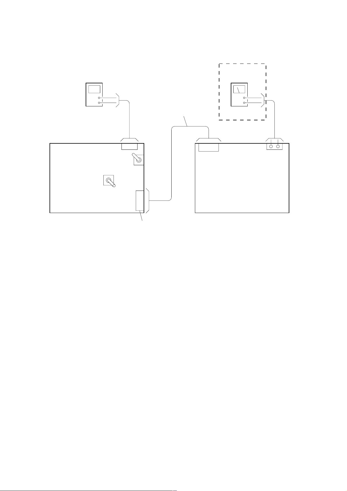
1. Connect the CDC (Changer) and Jig with the PANA-BUS connector.
2. Connect the power supply (+12V, GND) to the Jig.
3. Turn ON the POWER switch and the CTRLV switch. (See page 15)
Turning ON/OFF the CTRLV switch makes the ON/OFF control of the PANA-BUS command to the CDC (Changer).
4. For the LED adjustment, a luminance meter is required.
+
–
+
–
(Power supply)
CTRLV
POWER
switch
PANA-BUS
connector
PANA-BUS Cable
(DC+12V)
(Duty GEN.)
FRQ : 50 to 100Hz
Duty : 10 to 100%
LED adjustment mode only
Jig board
(SJ-5551 PANA BUS2)
(CDC: Changer)
22
CDX-5V661/5V661A/5V661D/5V661S
1. Normal operation mode (See “Display List” on page 18 and 19)
This mode checks normal operation and servo information.
Push key (execution key) assignment
Key Description
1 DISP –
2 DISP +
3 LOAD
4 EJECT
5 DISC key 1
6 DISC key 4
7 AMS –
8 AMS +
* Whether the PLAY key command or STOP key command is outputted is judged with the status received from the CDC.
(In the PLAY status, the STOP key command is active, or in the STOP status, the PLAY key command is active.)
How to enter the Check mode
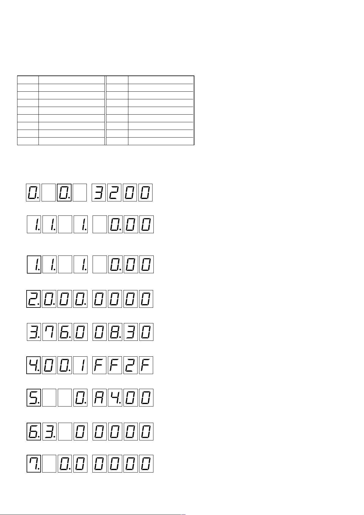
1. Rotating the rotary switch, adjust the display (7 Seg LED) to “0” (third place).
After 2 or 3 seconds, the display will change to the execution mode.
2. The display mode number can be changed by pressing 1 or 2 key.
(Example)
Press 2 key r R Press 1 key
Press 2 key r R Press 1 key
Press 2 key r R Press 1 key
Press 2 key r R Press 1 key
Press 2 key r R Press 1 key
Press 2 key r R Press 1 key
Press 2 key r R Press 1 key
: Software version display
: DTMS displa
y
: DTMS displa
y
: Servo information 1 displa
y
: Servo information 2 displa
y
: Servo information 3 displa
y
: Mechanism displa
y
: Aging displa
y
: Line 1 displa
y
Key Description
9 DISC key 2
0 DISC key 5
qa REV
qs CUE
qd DISC key 3
qf DISC key 6
qg ESP
qh PLAY/STOP (*)
23
CDX-5V661/5V661A/5V661D/5V661S
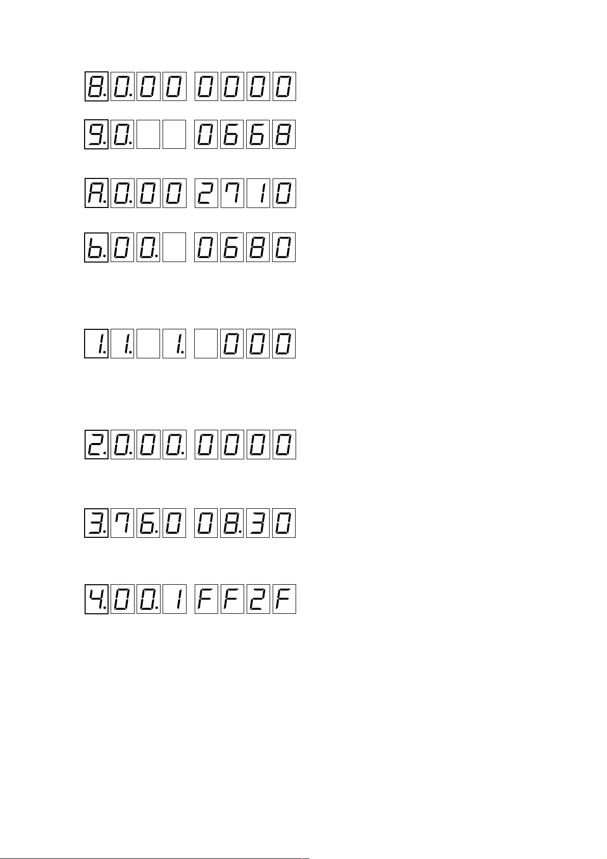
Press 2 key r R Press 1 key
Press 2 key r R Press 1 key
Press 2 key r R Press 1 key
Normal Operation Check (See “Display List” on page 18 and 19)
(Example)
1. Execution mode
2. Press 3 key, and load a disc. (See “Disc Loading Method” on page 20)
3. Press qh key to check the DTMS in the PLAY status
4. Press other keys to check each operation.
5. Press qh key (STOP).
6. Press 2 key to enter the servo information mode 1.
7. Press qh key to check the servo information 1 in the PLAY status.
8. Press qh key (STOP).
9. Press 2 key to enter the servo information mode 2.
10. Press qh key to check the servo information 2 in the PLAY status.
11. Press qh key (STOP).
12. Press 2 key to enter the servo information mode 3.
13. Press qh key to check the servo information 3 in the PLAY status.
14. The check results of servo information 1-3 can be confirmed with the MODE LED.
: Line 2 displa
y
: LED PWM Adjustmen
t
: LED data displa
y
: DIAG displa
y
: DTMS displa
y
: Servo information 1 displa
y
: Servo information 2 displa
y
: Servo information 3 displa
y
24
CDX-5V661/5V661A/5V661D/5V661S
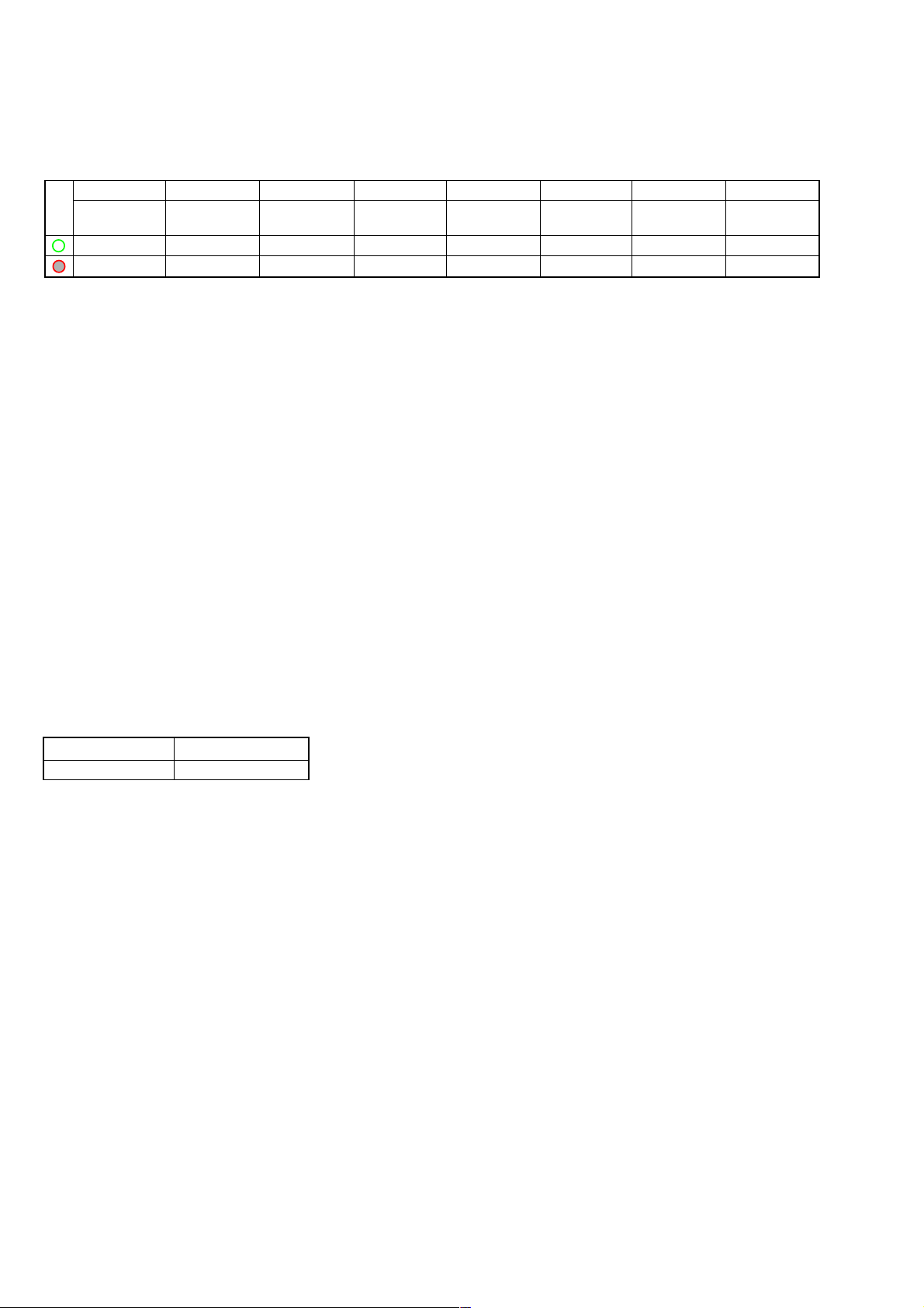
MODE LED Display
Green LED lights up: Normal
Red LED lights up: Abnormal (requiring repair)
L1 L2 L3 L4 L5 L6 L7 L8
ESP
DISC DISC Focus E-F Focus Tracking
Error Rate
CHECK CHECK Bias Balance Gain Gain
OFF × 1 OK (Note 1) ROM OK (Note 2) OK (Note 3) OK (Note 4) OK (Note 5) OK (Note 6)
OFF × 2 NG (Note 1) RW NG (Note 2) NG (Note 3) NG (Note 4) NG (Note 5) NG (Note 6)
Note 1:OK/NG range of RFDC
050h - 090h is OK.
Other range is NG.
Note 2:OK/NG r ange of Focus Bias
1E9h, 08h, 27h is OK.
Other range is NG.
Note 3:OK/NG range of E-F Balance
000h - 060h and 1A0h - 1FFh are OK.
Other range is NG.
Note 4:OK/NG r ange of Focus Gain
18h - 60h is OK.
Other range is NG.
Note 5: OK/NG range of Tracking Gain
18h - 60h is OK.
Other range is NG.
Note 6:OK/NG range of Error Rate
0000 - 0050 is OK.
Other range is NG.
Conditions:
• All items are checked in the PLAY status only.
• Once the Error Rate becomes NG, the NG status is held unless the operation is stopped and the disc is changed.
• Data clear timing t Operation stop and disc change
• OK/NG decision is a standard which is made under the condition that P ATD-012 (test disk) is used and that the temperature of inside of
the machine is 25°C.
Under different condition, the decision might be different.
Default display mode
Display mode No. Description
1 DTMS
25
CDX-5V661/5V661A/5V661D/5V661S
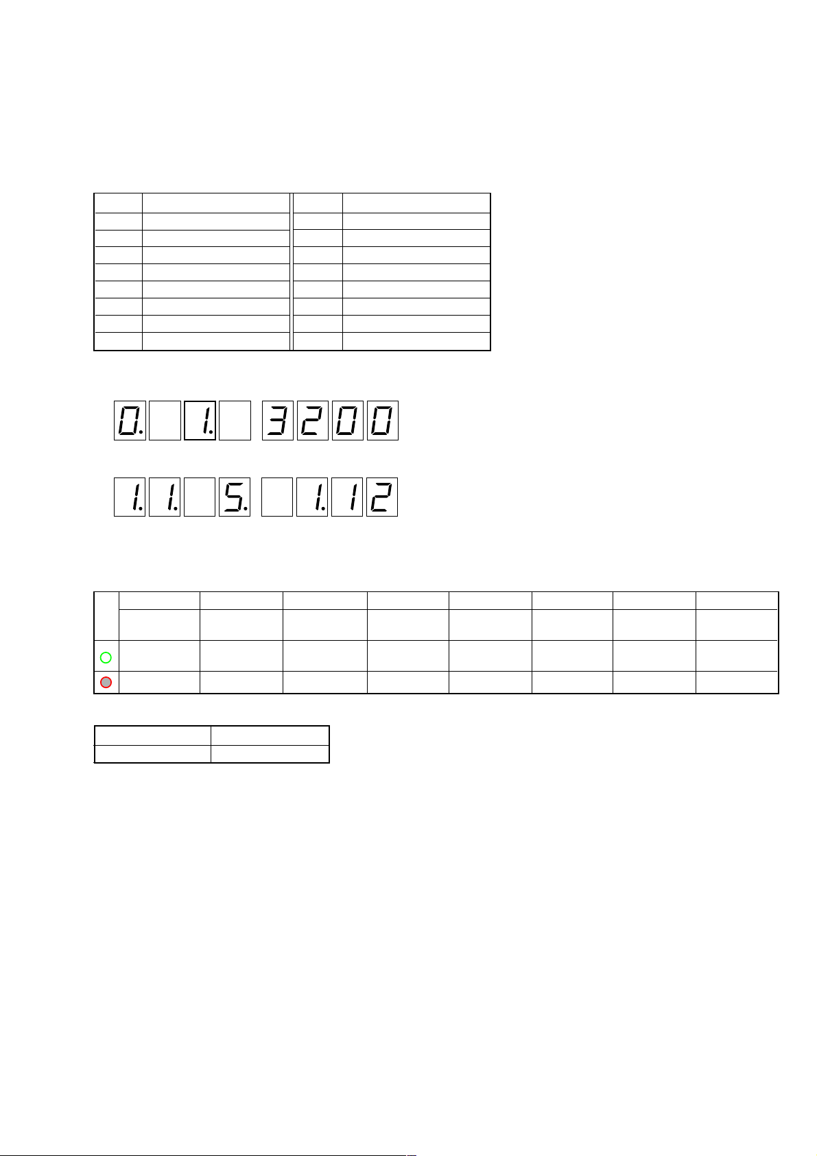
How to enter the Check mode
1. Rotating the rotary switch, adjust the display (7 Seg LED) to “1” (third place).
2. After 2 or 3 seconds, the display will change to the execution mode.
3. Load a disc. (See “Disc Loading Method” on page 20)
4. Each operation can be checked with the push keys.
MODE LED display
L1 L2 L3 L4 L5 L6 L7 L8
RANDAM SCAN
RANDAM
––– ––
ALL
ON: Light up ON: Light up ON: Light up
––– ––
OFF: Go off OFF: Go off OFF: Go off
––– ––– ––
2. Special Operation Mode
This mode can check the CD operations such as scan, repeat, and random.
(Changer control check function by issuing PANA-BUS commands)
Push key (execution key) assignment
Key Description
1 SCAN IN A DISC
2 SCAN ALL
3
4
5 DISC SHUFFLE
6 MAGAZINE SHUFFLE
7 DISC DOWN
8 DISC UP
: Software version displa
y
: DTMS displa
y
Default display mode
Display mode No. Description
1 DTMS
Key Description
9 RANDOM 1
0 RANDOM ALL
qa
TRACK SEARCH DOWN
qs TRACK SEARCH UP
qd REPEAT/RANDOM
qf NOP
qg PAUSE
qh PLAY 2/STOP
26
CDX-5V661/5V661A/5V661D/5V661S
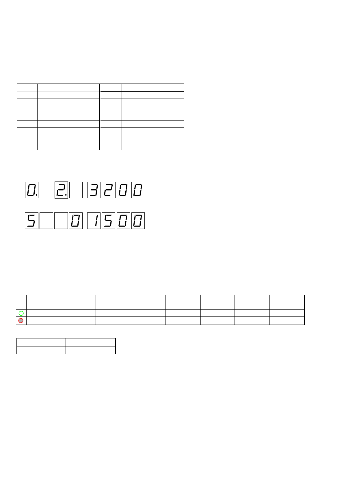
MODE LED display
L1 L2 L3 L4 L5 L6 L7 L8
––– ––– ––
––– ––– ––
––– ––– ––
* The check results of each key cannot be confirmed with the MODE LED.
How to enter the Check mode
1. Rotating the rotary switch, adjust the display (7 Seg LED) to “2” (third place).
After 2 or 3 seconds, the display will change to the execution mode.
2. The display mode number can be changed by pressing the 1 and 2 keys.
(See “Example” in step 2 in the Normal mode on page 22 and 23)
3. Press 3 and 4 keys to check manually the elevator motor operation.
4. Press 7 and 8 keys to check manually the loading motor operation.
5. Press qa and qs keys to check manually the divider motor operation.
6. The linear position can be adjusted by pressing qh key.
For the adjusted values and adjustment results, see “Display List” (page 18 and 19).
3. Mechanism Check Mode (See “Display List” on page 18 and 19)
This mode can adjust the linear position and check manually the operation of the elevator motor, loading motor, and divider motor.
Also, the disc can be ejected forcibly by moving each motor manually.
However, manual operation could destroy the mechanism depending on the mechanical position, thus requiring extreme care.
Push key (execution key) assignment
: Software version displa
y
: DTMS displa
y
Default display mode
Display mode No. Description
5 Mechanism
Key Description
1 DISP –
2 DISP +
3 ELEVATOR MOTOR -
4 ELEVATOR MOTOR +
5
6
7 LOADING MOTOR -
8 LOADING MOTOR +
Key Description
9
0
qa DIVIDER MOTOR –
qs DIVIDER MOTOR +
qd
qf
qg
qh LINEAR POSITION ADJUST
Loading...