


 Loading...
*9000510260* 9000510260 |
940725 |
|
|
|
|
||
Ø Montageanleitung |
|
ê Monteringsveiledning |
|
Ú Installation instructions |
|
Ù Οδηγίες εγκατάστασης |
|
Û Instrucciones de montaje |
|
ó Monteringsanvisning |
|
Þ Notice de montage |
|
Ý Asennusohje |
|
â Istruzioni per il montaggio |
|
ë Instrukcja montażu |
|
é Installatievoorschrift |
|
ô Montaj kılavuzu |
|
× Monteringsvejledning |
|
î Инструкция по монтажу |
|
ì Instruções de montagem |
|
|
|
|
|
|
|
|
|
|
|
PD[ 5 |
5 |
|
|
|
|
|
|
|
|
|
|
||
|
|
|
|
[ |
|
|
|
|
|
|
|
|
|
|
|
|
|
|
|
|
|
|
|
|
|
|
|
|
|
% |
|
$ |
% |
|
|
|
|
||||
|
|
PLQ |
|
PLQ |
PLQ |
|
PLQ |
|
& |
|
|||
|
|
|
PLQ |
PLQ |
|
|
|
|
|
|
|
||
|
|
|
|
|
|
|
PLQ |
PLQ |
|
& PLQ PLQ |
|
||
|
|
|
|
|||
|
$ |
|
|
|
|
|
D |
E |
F |
PLQ |
|
PLQ |
PLQ |
|
|
|
PLQ |
|
PLQ |
PLQ |
$ |

PLQ |
PLQ |
$ |
$ |
$ |
PLQ |
$ |
$ |
$ |
9 1a
 /
/
 1
1
|
|
|
9 9 1a |
|
|
|
|
|
|
/ |
|
|
|
9 |
9 |
|
/ |
|
9 |
9 |
|
9 |
9 |
||||
|
|
|
1 |
|
|
|
|
|
|
|
|
|
|
|
|
|
|
|
|
|
|
9 9 / 1a |
||
|
|
|
1/ |
|
/ |
9 |
9 |
|
/ |
||
|
1 |
|
9 9 |
|
|
|
|
|
1 |
|
|
|
|
|
|

de
Ø
Wichtige Hinweise
Die Sicherheit während des Gebrauchs ist nur gewährleistet, wenn der Einbau technisch korrekt und gemäß diesen Montageanweisungen vorgenommen wurde. Schäden, die durch einen unsachgemäßen Einbau entstehen, liegen in der Verantwortung des Monteurs.
Das Gerät darf nur von einem qualifizierten Fachmann angeschlossen werden. Dabei gelten die Bestimmungen der örtlichen Stromversorger.
Dieses Gerät entspricht Schutzklasse I und darf nur mit einem Erdungsanschluss betrieben werden.
Die Benutzung dieses Geräts ohne Erdungsanschluss oder der unsachgemäße Einbau kann schwerwiegende Schäden verursachen.
Der Hersteller übernimmt keine Verantwortung für den unsachgemäßen Betrieb oder mögliche Schäden wegen fehlerhafter elektrischer Installationen.
Das Gerät muss fest eingebaut werden, und es müssen beim festen Einbau gemäß den Montagevorschriften Trennungsmöglichkeiten berücksichtigt werden.
Das Netzkabel muss so angebracht werden, dass heiße Teile des Kochfelds oder Backofens nicht berührt werden.
Induktionskochfelder dürfen nur über Backöfen mit Gebläse desselben Herstellers eingebaut werden. Unter dem Kochfeld dürfen keine Kühlschränke, Geschirrspüler, Backöfen ohne Gebläse oder Waschmaschinen eingebaut werden.
Wenn das Kochfeld über einem Schubfach eingebaut wurde, können im Schubfach befindliche Metallgegenstände hohe Temperaturen durch den Rückstrom der Luft aus dem Umluftbetrieb des Kochfelds erreichen. Daher wird empfohlen, einen Zwischenboden einzubauen (Abb. 2a).
Jegliche Arbeiten im Geräteinneren, einschließlich Austausch des Netzkabels, müssen vom Kundendienst vorgenommen werden.
Unsachgemäßer Einbau führt zum Verlust der Garantie.
Vorbereitung der Einbaumöbel, Abb. 1, 2, 3, 4
Arbeitsplatte:
Die Arbeitsplatte muss eben und waagerecht sein. Der Zuschnitt des Möbels muss vor Einbau des Geräts erfolgen. Späne entfernen, andernfalls ist der korrekte Betrieb der elektrischen Komponenten nicht gewährleistet. Die Stabilität der Küchenmöbel muss auch nach erfolgten Schnittarbeiten gewährleistet sein.
■Die Schnittflächen müssen hitzebeständig versiegelt werden, damit sie bei Feuchtigkeit nicht aufquellen.
■Einbaumöbel müssen bis 90 ºC hitzebeständig sein.
■Wenn die Stärke der Arbeitsplatte, in die das Kochfeld eingebaut wird, weniger als 30 mm beträgt, sollte sie mit einem hitzeund wasserbeständigen Material verstärkt werden. Andernfalls ist sie nicht stabil genug.
Hinweise
■Die Arbeitsplatte, in die das Kochfeld eingebaut wird, muss über eine Tragfähigkeit von etwa 60 kg verfügen.
■Die Ebenheit des Kochfelds erst nach Installation in der Einbauöffnung überprüfen.
Das Gerät kann in folgende hitzeund wasserbeständige Arbeitsplatten eingebaut werden:
■Arbeitsplatten aus Marmor oder Naturstein
■Synthetische Arbeitsplatten
■Arbeitsplatten aus Massivholz: Nur nach Vorgaben des Herstellers der Arbeitsplatte (Versiegelung der Schnittkanten)
■Einbau in andere Arten von Arbeitsplatten: Nur nach Vorgaben des Herstellers der Arbeitsplatte
Hinweis: Alle Schnittarbeiten an der Arbeitsplatte müssen von Fachpersonal laut Einbauskizze durchgeführt werden. Der Zuschnitt muss sauber und präzise erfolgen, da die Schnittkante an der Oberfläche sichtbar ist. Die Schnittkanten mit einem geeigneten Reinigungsmittel reinigen und entfetten (Angaben des Silikonherstellers beachten).
Lüftung, Abb. 2:
Für die Lüftung des Kochfelds ist Folgendes notwendig:
■eine Öffnung im oberen Bereich der Rückwand des Möbels
(Abb. 2a).
■eine Trennung zwischen der Rückwand des Möbels und der Küchenwand (Abb. 2b).
■Wenn die Breite des Möbels (Innenmaß) weniger als 780 mm beträgt, sollte an den Seitenwänden ein Schnitt durchgeführt werden (Abb. 2c).
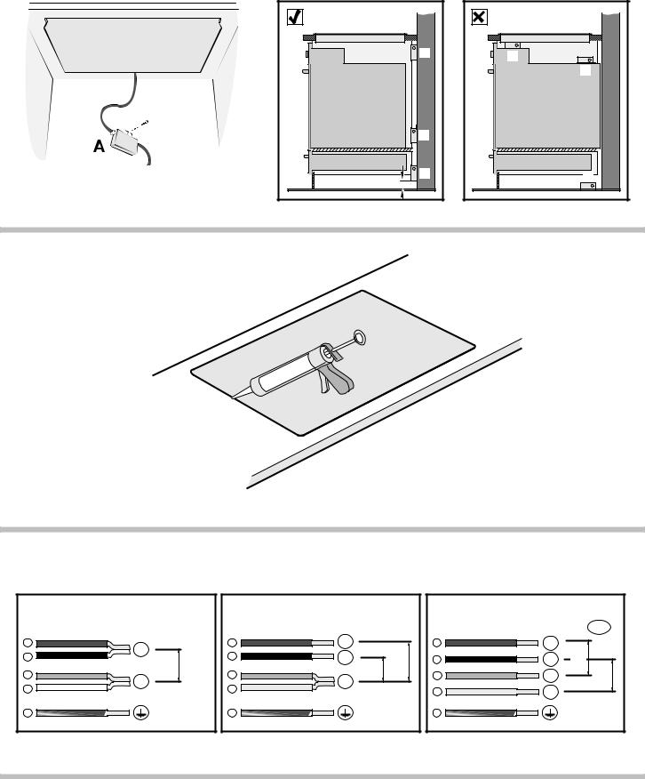
Verbindungskabel, Abb. 3:
Das Anschlusskabel nicht einklemmen:
■Wird das Kochfeld auf einem Schubfach oder einem Zwischenboden eingebaut, muss ein Mindestabstand von 70 mm zwischen Schubfach bzw. Zwischenboden und Oberseite der Arbeitsplatte gelassen werden.
■Erfolgt der Einbau auf einem festen Möbel, muss ein Mindestabstand von 100 mm zwischen Möbel und Oberseite der Arbeitsplatte gelassen werden.
Klebedichtung, Abb. 4:
Die Klebedichtung zentral auf dem Absatz der Arbeitsplatte anbringen.
Einbau des Geräts, Abb. 5/6/7/8
Hinweis: Zum Einbauen des Kochfeldes Schutzhandschuhe verwenden. Die nicht sichtbaren Flächen können scharfe Kanten aufweisen.
Hinweis: Das Gerät wiegt zu viel. Es wird daher empfohlen, den Einbau von zwei Personen vornehmen zu lassen.
1.Das Gerät gleichmäßig in den zugeschnittenen Bereich setzen. Fest von oben in den zugeschnittenen Bereich pressen.
Hinweis: Das Gerät muss fest im zugeschnittenen Bereich sitzen und darf sich nicht bewegen (z. B. bei der Reinigung). Liegt die Breite des zugeschnittenen Bereichs an der oberen Toleranzgrenze, je nach Bedarf seitliche Leisten am Schnitt anbringen.
2.Überprüfen, ob das Kochfeld auf gleicher Höhe mit der Arbeitsplatte liegt. Falls das Kochfeld nicht ausgerichtet werden kann, die mitgelieferten Verankerungen nur an den notwendigen Punkten anbringen und vorsichtig festziehen,
(Abb. 5).
Hinweis: Keine elektrischen Schraubendreher verwenden.
3.Die Filterbox anbringen (Abb. 6).
4.Gerät an das Netz anschließen und Funktion prüfen.
–Spannung siehe Typenschild.
–Nur gemäß Anschlussbild anschließen (Abbildung 8).
1.Braun
2.Schwarz
3.Blau
4.Grau
5.Grün-gelb
Hinweis: Je nach Anschlussart muss eventuell die Anordnung der vom Werk gelieferten Klemmen verändert werden.
5.Vor dem Abdichten (Abb. 7) unbedingt einen Betriebstest durchführen!
Den Abstand zwischen den Bereichen mit geeignetem hitzebeständigen Silikon (z. B. Novasil®S70, Ottoseal®S70) abdichten. Die hermetische Dichtung mit einem vom Hersteller empfohlenen Produkt glätten. Die Angaben auf dem Silikon beachten.
Das Gerät nicht in Betrieb nehmen, bevor das Silikon vollständig getrocknet ist (je nach Umgebungstemperatur, mindestens 24 Stunden).
Geeignetes Silikon kann bei unserem Kundendienst erworben werden.
Achtung!
Wird bei Arbeitsplatten aus Naturmarmor ungeeignetes Silikon verwendet, können Verfärbungen entstehen, die nicht entfernt werden können.
Ausbau des Geräts
Das Gerät von der Stromzufuhr trennen.
Die Silikondichtung der gesamten Umrandung des Kochfelds mit einem geeigneten Werkzeug entfernen.
Die Halterungen entfernen.
Entnehmen Sie das Kochfeld, indem Sie von unten dagegen drücken.

Achtung!
Schäden am Gerät! Versuchen Sie nicht, das Gerät durch Hebeln von oben zu entnehmen.
en
Ú
Important notes
Safety in use is only guaranteed if the technical installation of the hob has been carried out correctly and in accordance with the installation instructions. The installation technician shall be liable for any damage caused as a result of incorrect installation.
Only an authorised technician is able to connect the appliance. The guidelines set out by the local electricity provider must be observed.
This is a class I appliance and should only be used with an earthed connection.
Using this appliance without an earth connection or after it has been incorrectly installed may, under very rare circumstances, cause serious harm.
The manufacturer accepts no responsibility for any malfunction or damage caused by incorrect electrical installation.
The appliance must be connected to a fixed installation and the means of disconnecting it from the fixed installation must be included according to the installation instructions.
The inlet hose must be positioned so that it does not touch any of the hot parts of the hob or oven.
Induction hobs may only be installed over ovens with the same brand of forced-air ventilation. Refrigerators, unventilated ovens, and washing machines may not be installed beneath the hob.
If the hob has been installed over a drawer, any metallic objects found in the drawer may reach high temperatures due to the recirculation of the air coming from the hob's ventilation. In this case, an intermediary support is recommended (Figure 2a).
Any change to the appliance's interior, including changing the power cable, must be performed by the Technical Assistance Service.
An unsuitable installation will invalidate the warranty.
Preparation of assembly units, figures 1/2/3/4
Worktop:
The worktop should be flat and horizontal. The cuts should be made in the kitchen unit before installing the appliance. Remove any shavings, as these can affect the operation of the electrical components. When the cutouts have been made, the unit's stability should be checked again.
■Surfaces which have been cut should be sealed so that they are heat-resistant and so that they do not swell due to humidity.
■The built-in kitchen units must withstand temperatures of up to 90 ºC.
■If the thickness of the worktop where the hob is installed is less than 30 mm., reinforce the worktop with a material resistant to temperature and water. Otherwise it won't be sufficiently stable.
Notes
■The worktop where the hob is installed should be able to support a weight of approximately 60 kg.
■The hob levelling should only be checked after it is installed in the gap for the built-in unit.
The appliance can be mounted on the following heat and water resistant worktops:
■Marble, natural stone worktops
■Synthetic worktops
■Solid wood worktops: only according to the manufacturer of the worktop (sealing of cutout edges)
■Assembly with other types of worktops: only according to the manufacturer of the worktop
Note: All worktop cutout work must be carried out by a specialised service according to the assembly drawings. The cutout must be clean and precise, as the cut edge will be visible on the surface. Clean and degrease the cutout edges using a suitable cleaning product (check the silicone manufacturer's indications).
Ventilation, figure 2:
Ventilating the hob requires:
■An opening on the upper part of the unit's rear wall
(figure 2a).
■A separation between the rear part of the unit and kitchen wall
(figure 2b).
■If the interior width of the unit is less than 780 mm., a cut must be made in the lateral walls (figure 2c).
Connection cable, figure 3:
Do not tie the connection cable:
■If the hob is installed on a drawer or intermediate support, a minimum gap of 70 mm must be left between the drawer or support and the top of the worktop.
■If installed on a fixed unit, leave a minimum gap of 100 mm between the unit and the top of the worktop.
Adhesive seal, figure 4:
Adhere the adhesive seal to the stepped rim of the worktop.
Installing the appliance, figures 5/6/7/8
Note: Wear protective gloves to fit the hob. The non-visible surfaces may have sharp edges.
Note: The appliance is too heavy. It is recommended that two persons insert it.
1.Insert the appliance uniformly in the cutout. Press it down firmly into the cutout.
Note: The appliance must be firmly embedded in the cutout and should not move (e.g. when cleaning it). If the width of the cutout is at the upper tolerance limit, attach side strips to the cutout as required.
2.Check that the hob is flush with the worktop. If the hob is not flush, install the anchoring devices supplied only in the points necessary and tighten them carefully, (figure 5).
Note: Do not use electric screwdrivers.
3.Install the filter box (figure 6).
4.Connect the appliance to the mains and check that it works correctly.
–See the rating plate for the voltage.
–Only connect the appliance in accordance with the connection diagram (Fig. 8).
1.Brown
2.Black
3.Blue
4.Grey
5.Green-yellow
Note: Depending on the type of connection, the arrangement of the clamps supplied by the factory may need to be changed.
5.Before sealing the joint (figure 7) you must test that the appliance works!
Grout the perimeter separation using appropriate, heat resistant silicone ( e.g. Novasil® S70, Ottoseal® S70). Smooth the seal with a finishing product recommended by the manufacturer. Follow the silicone indications. Do not start the appliance until the silicone is completely dry (minimum
24 hours, depending on the ambient temperature).
The appropriate silicones can be obtained through our Technical Assistance Service.
Caution!
The use of unsuitable silicone causes permanent colour changes to natural marble worktops.
Uninstalling the appliance
Disconnect the appliance from the mains.
Remove the silicone seal from the edge of the hob with a suitable tool.
Remove the anchoring devices.
Push the hob upwards from below to remove it.
Caution!
Damage to the appliance! Do not try to remove the appliance by pulling it from above.

es
Û
Observaciones importantes
La seguridad durante el uso sólo está garantizada si la instalación se ha efectuado de manera correcta en el aspecto técnico y en conformidad con estas instrucciones de montaje. Los daños causados por un montaje inadecuado serán responsabilidad del instalador.
Sólo puede efectuar la conexión del aparato un técnico especialista autorizado. Se tendrá que regir por las disposiciones de la compañía abastecedora de electricidad de la zona.
El aparato corresponde al tipo de protección I y sólo se puede utilizar con una conexión con puesta a tierra.
El uso de este aparato sin la conexión de tierra o con una instalación incorrecta puede causar, aunque en circunstancias muy poco probables, daños serios.
El fabricante no se hace responsable del funcionamiento inadecuado y de los posibles daños motivados por instalaciones eléctricas no adecuadas.
El aparato debe ser conectado a una instalación fija y deben ser incorporados medios de desconexión a la instalación fija de acuerdo a las reglamentaciones de la instalación.
La manguera de alimentación debe colocarse de manera que no toque partes calientes de la placa de cocción o del horno.
Las placas de inducción sólo pueden ser instaladas sobre hornos con ventilación forzada de la misma marca. Debajo de la placa de cocción no se pueden instalar frigoríficos, lavavajillas, hornos sin ventilación o lavadoras.
Si la placa se ha instalado sobre cajón, los objetos metálicos que se encuentren en el cajón podrían alcanzar temperaturas elevadas debido a la recirculación del aire procedente de la ventilación de la placa, si esto ocurre, se recomienda utilizar un soporte intermedio (Figura 2a).
Cualquier manipulación en el interior del aparato, incluyendo el cambio del cable de alimentación, debe ser realizada por el Servicio de Asistencia Técnica.
Una instalación inadecuada supone la pérdida de validez de la garantía del producto.
Preparación de los muebles de montaje, figuras 1/2/3/4
Encimera:
La encimera debe ser plana y horizontal. Los cortes en el mueble se deben hacer antes de la instalación del aparato. Retirar las virutas, el funcionamiento de los componentes eléctricos puede verse afectado. La estabilidad de los muebles también debe quedar garantizada después de haber relizado los trabajos de recorte.
■Las superficies de corte deben sellarse de manera que sean resistentes al calor y así evitar que se hinchen a causa de la humedad.
■Los muebles para emportar deben ser resistentes a temperaturas de hasta 90 °C.
■Si el grosor de la encimera donde se instale la placa es menor de 30 mm, refuerce la encimera con un material resistente a la temperatura y al agua. De otra forma no se alcanzará una estabilidad suficiente.
Notas
■La encimera donde se instale la placa debe ser resitente a pesos de 60 kg aproximadamente.
■La planitud de la placa de cocción sólo debe comprobarse una vez instalada en el hueco de encastre.
El aparato se puede montar en las siguientes encimeras resistentes a la temperatura y al agua:
■Encimeras de mármol, piedra natural
■Encimeras sintéticas
■Encimeras de madera maciza: sólo de acuerdo con el fabricante de la encimera (sellado de los bordes de recorte)
■Montaje en otro tipo de encimeras: sólo de acuerdo con el fabricante de la encimera
Nota: Todos los trabajos de recorte de la encimera deben ser realizados por un servicio especializado de acuerdo con el croquis de montaje. El recorte debe ser limpio y preciso, puesto que el borde cortado se ve en la superficie. Limpie y desengrase los bordes de recorte utilizando un producto de limpieza adecuado (consulte las indicaciones del fabricante de la silicona).
Ventilación, figura 2:
Teniendo en cuenta la ventilación de la placa, es necesario:
■una abertura en la parte superior de la pared trasera del mueble (figura 2a).
■una separación entre la parte trasera del mueble y la pared de la cocina (figura 2b).
■Si la anchura interior del mueble es menor de 780 mm., se debe hacer un corte en las paredes laterales (figura 2c).
Cable de conexión, figura 3:
No aprisionar el cable de conexión:
■Si la placa se instala sobre cajón o sobre un soporte intermedio, debe dejarse como mínimo 70 mm de distancia entre el cajón o el soporte y la parte superior de la encimera.
■Si se instala sobre un mueble fijo, debe dejarse como mínimo 100 mm de distancia entre el mueble y la parte superior de la encimera.
Junta adhesiva, figura 4:
Pegar la junta adhesiva centrada sobre el escalón de la encimera.
Instalar el aparato, figuras 5/6/7/8
Nota: Usar guantes de protección al instalar la placa. Las superficies no visibles pueden tener aristas cortantes.
Nota: El aparato pesa demasiado. Se aconseja dos personas para insertarlo.
1.Introduzca el aparato uniformemente en el recorte. Presiónelo firmemente en el recorte desde arriba.
Nota: El aparato debe quedar asentado firmemente en el recorte y no debe moverse (p.ej. al limpiarlo). Si la anchura del recorte se encuentra en el límite de tolerancia superior, fije regletas laterales en el recorte según necesidad.
2.Comprobar que la placa de cocción quede a nivel con la encimera. En el caso de que la placa no quede a nivel, instalar los anclajes suministrados únicamente en los puntos necesarios y ajustarlos con cuidado, (figura 5).
Nota: No utilizar destornilladores eléctricos.
3.Colocar la caja filtro (figura 6).
4.Conectar el aparato a la red eléctrica y compruebe su funcionamiento.
–Tensión, ver placa de características.
–Concectar exclusivamente según el esquema de conexión
(figura 8).
1.Marrón
2.Negro
3.Azul
4.Gris
5.Amarillo y verde
Nota: Según el tipo de conexión puede ser necesario modificar la disposición de los terminales suministrados por fábrica.
5.¡Antes del sellado con junta (figura 7) ha de realizar necesariamente una prueba de funcionamiento!
Rejunte la separación perimétrica utilizando silicona adecuada y termorresistente ( p. ej. Novasil® S70, Ottoseal® S70). Alise la junta de hermetizado con el producto de alisado recomendado por el fabricante. Observe las indicaciones de la silicona. No ponga en marcha el aparato hasta que la silicona esté completamente seca (como mínimo 24 horas, dependiendo de la temperatura ambiente).
En nuestro Servicio de Asistencia Técnica se pueden adquirir siliconas adecuadas.
¡Atención!
El uso de silicona inadecuada provoca cambios de color permanentes en las encimeras de mármol natural.
Desmontar el aparato
Desconectar el aparato de la red eléctrica.
Retirar la junta de silicona de todo el contorno de la placa con una herramienta adecuada.
Quitar los anclajes de sujección.
Extraer la placa de cocción ejerciendo presión desde abajo.
¡Atención!
¡Daños en el aparato! No intente extraer el aparato haciendo palanca desde arriba.
Loading...