


RICOH
RICOH F T 2 0 5 0 / 2 0 70
F I E L D S E R V I C E M A N U A L
RICOH COMPANY LTD.

CONTENTS
SECTION 1 : INSTALLATION REQUIREMENTS
SECTION 2: UNPACKING AND INSTALLATION
SECTION 3: PREPARATIONS FOR TRANSPORTING THE COPIER SECTION 4: SERVICE TABLES AND REMARKS
SECTION 5: REPLACEMENT AND ADJUSTMENT SECTION 6: SORTER CS1040
SECTION 7: DOCUMENT FEEDER DF36
SECTION 8: TROUBLE SHOOTING
SECTION 9: ELECTRICAL DATA

CAUTIONS
1.Before installing the machine, make sure that there is a suitable ground (earth) available.
2.Since some parts of the copier are supplied with high voltage, make sure the main switch is off and the power supply cord is unpluged before working on the copier.
3.When working on the fusing section, make sure that the fusing unit is cold.
4.When standing the clamshell straight up, place a block that has a height of approximately 80 mm (approx. 3") in front of the exit cover.
5.Do not turn on the safety switch when the clamshell is open.
SECTION 1
INSTALLATION REQUIREMENTS
1-1. Environment
1.Temperature Range : 10°C to 30°C
(50°F to 86°F)
2. H u m i d i t y R a n g e : 15% to 90% RR
3.Ambient Illumination : Less than 1,500 Iuxs (Do
not expose to direct sunlight)
4. Ventilation : Room air should turn over at least 3 times/hour.
5. |
Ambient |
Dust |
: |
Less than 0.1 5mg/m3 |
6. |
Room Size |
|
.. |
More than 10m³ (13.4 yd³) |
7.If the installation place is air-conditioned or heated, place the machine:
a.Where it will not be subjected to sudden temperature changes from low to high, or vice versa.
b.Where it will not be directly exposed to cool air from an air conditioner in the summer.
c.Where it will not be directly exposed to reflected heat from a space heater in winter.
8.Avoid placing the copier in an area filled with corrosive gas.
9.Avoid any area higher than 2,000m (6,500 feet) above sea level.
10.Place the copier on a strong and level base.
11.Avoid any area where the copier may be subjected to frequent strong vibration.
1-1
February 1. 1986
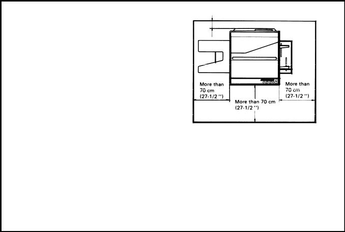
1-2. Minimum Space Requirements
1.Front :70 cm (27-1/2")
2.Back :12 cm (4-3/4")
3.Right :70 cm (27-1/2")
4. Left :70 cm (27-1 /2")
1-3. Power Source
1. Input voltage level
110V/60Hz : More than 12A 115V/60Hz : More than 12A 220V/50Hz : More than 6A 240V/50Hz : More than 6A
2. Permissible voltage fluctuation: ±10%
More than 12 cm (4-3/4")
3. Permissible extension cord:
At least 300V, 30A capacity and less than 5m (16.4") long.
Note: 1. Be sure to ground the machine.
(Do not connect the grounding wire to a gas pipe.
2.Make sure the plug is firmly inserted in the outlet.
3.Avoid multi-wiring.
4.Do not set anything on the power cord.
1-2
SECTION 2
UNPACKING
AND
INSTALLATION
August 1, 1985
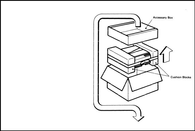
2-1. Unpacking Procedure
1.Take out the accessory box and the machine.
2.Remove the two cushion blocks.
3.Open the vinyl bag and take out the machine.
2-1
August 1, 1985
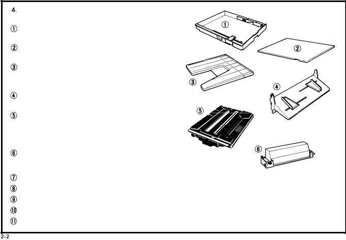
Check that the accessories are in the quantities according to the following list.
Cassette . . . . . . . . . . . . . . . . . . . . . . . . . . . . . . 2 pcs. (One is in the machine.)
Cassette Cover . . . . . . . . . . . . . . . . . . . . . . . ..1 pc
Copy Tray . . . . . . . . . . . . . . . . . . . . . . . . . . . . . 1 pc
Manual Feed Guide . . . . . . . . . . . . . . . . . . . . . . 1 pc
Master Unit . . . . . . . . . . . . . . . . . . . . . . . . . . . . 1 pc
NOTE: Keep it in the box until installing it in the copier.
Toner . . . . . . . . . . . . . . . . . . . . . . 1 cartridge (Black)
●
Operating instructions . . . . . . . . . . . . . . . . . . . 1 pc
N.E.C.R . . . . . . . . . . . . . . . . . . . . . . . . . . . . . . . . . 1 pc
Envelope for N.E.C.R. (115Vonly) . . . . . . . . . 1 pc Multi-lingualDecal(220/240Vonly) . . . . . . . 1 pc Paper Size Decal . . . . . . . . . . . . . . . . . . . . . . . . 1 pc
2-2. Installation Procedure
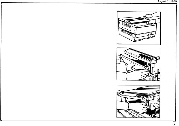
1. Remove the two strips of tape.
2. Open the front cover.
3.Move the slider to the center and push down the release lever to open the top unit.
2
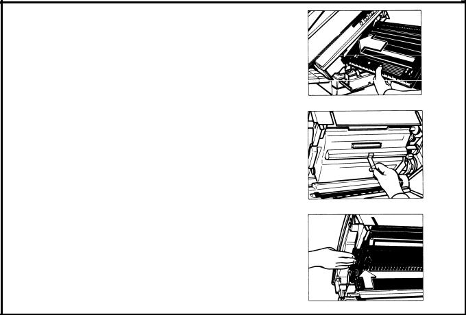
4. Remove the roller retainer.
5. Remove the two strips of tape.
6.Remove the three wedges from the new master unit.
Note: Do not touch the master (purple material) and avoid exposing it to light.
2 - 4
August 1, 198 
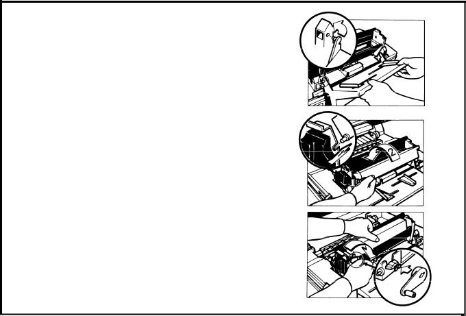
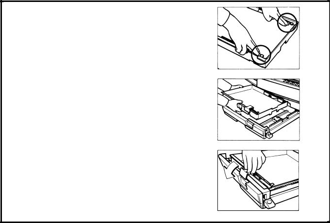
7. Insert the master unit into the copier.
8.Peel off the  cover that protects the master.
9. Push the master unit up until it locks in place.
2-5
August 1, 1985
10.Install the manual feed guide on the right side of the machine.
11.Shake the new cartridge of toner well.
12.Set the pins of the toner cartridge into the slots on the development unit. Then, turn the cartridge counterclockwise.
13.Install the cartridge crank onto the shaft and turn the cartridge crank clockwise to strip off the cartridge seal.
Then, remove the cartridge crank and lower the top unit.
Note: At installation, it is recommended to load two cartridges of toner.
2-6
August 1, 1985
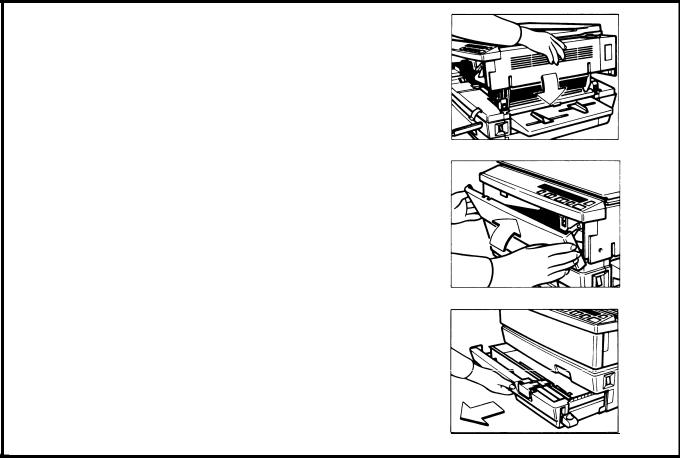
14.Lower the top unit.
15.Close the front cover.
16.Pull out the cassette tray unit it stops
L I
2 - 7

August 1, 1985
17. Remove the strip of tape and the silica gel.
18. Take out the cassette and the two cushion blocks.
I 19. Load paper into the cassette so that it is flush with
I |
the front and side fences. |
|
NOTE: The cassette holds approximately 250 |
|
sheets. |
|
|
2-8
August 1, 198 
20.Press down the corners of the paper stack so that they catch underneath the corner separators.
21.Set the cassette on the cassette tray.
22.Set the paper size flap.
2-9
August 1, 1985
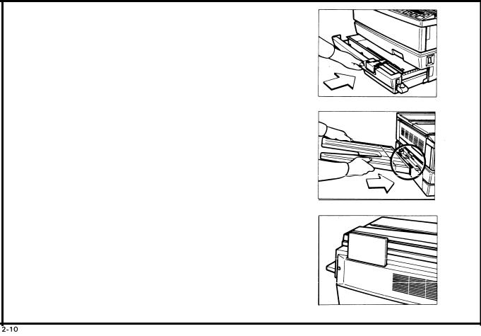
23. Push in the cassette tray until it stops.
24. Install the copy tray on the left side of the machine.
25.When not using this instruction booklet, place it in the holder on the back of the copier.
26.Check machine operation and copy quality.
Fill out the New Equipment Condition Report.
This completes machine installation.

2-3. Cassette Modification
1.Remove the side fences and the rear fence (1 screw each).
2.Reposition the fences to the desired paper size position.
3.Insert the actuators in the proper slots on the front of the cassette.
4.Attach the proper paper size decal on the paper size flap.
2-11
August 1, 1985
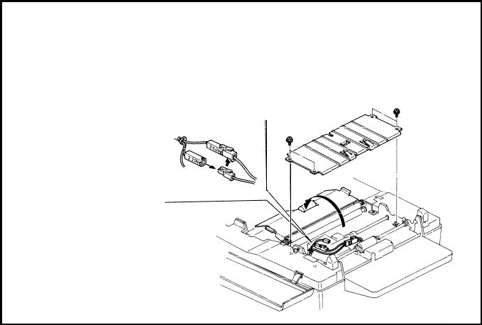
2-4. Main Transformer Conversion
(220 to 240V only)
1.Open the top unit and remove the development unit.
2.Swing up the upper feed guide (1 screw).
3.Remove the lower feed guide (4 screw).
4.Uncouple the 220V connector and couple the 240V connector.
2-12
August 1, 1985
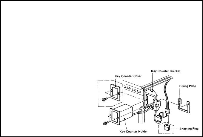
2-5. Key Counter Holder Installation
Note: Three types of counters are recommended for this copier (Ricoh, Hecon, and Hengstler key counters).
1.Remove the upper right cover (4 screws.)
2.Remove the key counter cover and fixing plate from the key counter bracket (2 screws).
3.Hold the fixing plate on the inside of the key counter bracket and insert the key holder.
2-13
4.Align the holes in the fixing plate with the mounting holes of the key counter holder and secure the key
counter holder.
Note: The fixing plate has three sets of holes. Make sure to use the holes that match the type of counter when installing.
5.Remove the shorting plug from the key counter connector.
Note: This shorting plug is usually on the harness.
6.Plug in the key counter harness.
7.Reassemble the copier. Insert the key counter and check its operation.
2 - 1 4
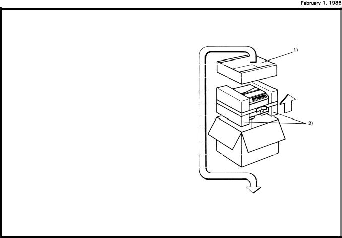
2-6. Unpacking Procedure
1.Take out the accessory box and the machine.
2.Remove the two cushion blocks.
3.Open the vinyl bag and take out the machine.
1 ) Accessory Box
2) Cushion Blocks
2-15
February 1, 1986
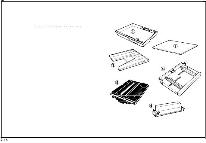
4.Check that the accessories are in the quantities according to the following list.
1] Cassette . . . . . . . . . . . . . . . . . . . . . . . . . . . . . . 2 pcs.
3 pcs. (Asia)
(One is in the machine.)
2) Cassette Cover . . . . . . . . . . . . . . . . . . . . . . . . . 1 pc 3) Copy Tray . . . . . . . . . . . . . . . . . . . . . . . . . . . . . 1 pc 4) Paper Tray . . . . . . . . . . . . . . . . . . . . . . . . . . . . . 1 pc 5) Master Unit . . . . . . . . . . . . . . . . . . . . . . . . . . . . 1 pc NOTE: Keep it in the box until installing it in the
copier.
6) Toner . . . . . . . . . . . . . . . . . . . . . . 1 cartridge (Black) 7) Operating Instructions . . . . . . . . . . . . . . . . . . . 1 pc 8) N.E.C.R . . . . . . . . . . . . . . . . . . . . . . . . . . . . . . . . . 1 pc 9) EnveIope for N.E.C.R. (USA only) . . . . . . . . . . 1 pc 1 0) Multi-lingualDecal(220/240V only) . . . . . . . 1 pc
11) Paper Size Decal . . . . . . . . . . . . . . . . . . . . . . . . 1 pc
February 1, 1986
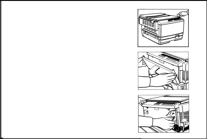
2-7. Installation Procedure
1, Remove the two strips of tape.
2.Open the front cover.
3.Move the slider to the center and push down the release lever to open the top unit.
2-17

February 1, 1986
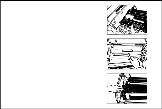
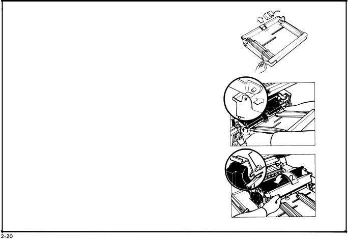
4. Remove the roller retainer.
5. Remove the two strips of tape.
6. Remove the three wedges from the new master unit.
Note: Do not touch the master (purple material) and avoid exposing it to light.
2-18
February 1, 1986
7. Insert the master unit into the copier,
8. Peel off the polyester cover that protects the master.
9. Push the master unit up until it locks in place.
2 - 1 9
February 1, 1986
10.Remove the two strips of tape and one cushion block from the paper tray.
11.Install the paper tray on the right side of the machine.
12. Shake the new cartridge of toner well.
13. Set the pins of the toner cartridge into the slots on the development unit. Then, turn the cartridge counterclockwise

Februarv 1. 1986
14.Install the cartridge crank onto the shaft and turn the cartridge crank clockwise to strip off the cartridge seal.
Then, remove the cartridge crank and lower the top unit.
Note: At installation, it is recommended to load two cartridges of toner.
15.Lower the top u-nit.
16. Close the front cover.
2-21

February 1, 1986
I |
1 |
17. Pull out the cassette tray unit it stops.
18. Remove the strip of tape and the silica gel. 1 ) Silica Gel
19. Take out the cassette and the two cushion blocks. 1 ) Cushion Blocks
Februarv 1. 1986
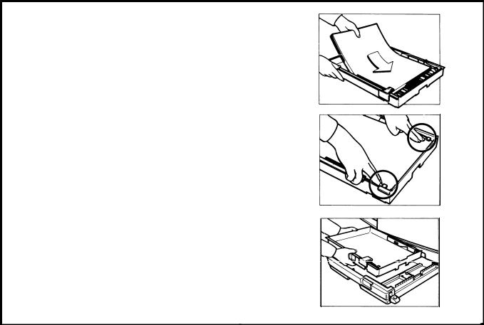
20. Load paper into the cassette so that it is flush with the front and side fences.
Note: The cassette holds approximately 250 sheets.
21. Press down the corners of the paper stack so that they catch underneath the corner separators.
22. Set the cassette on the cassette tray.
2 - 2 3
 Loading...