


Af1013
Table of contents
 Loading...
Model S-C1
(Machine Code: B045/B049/B044/B046)
SERVICE MANUAL
B046I100.WMF
17 July, 2001
Subject to change

!
IMPORTANT SAFETY NOTICES
PREVENTION OF PHYSICAL INJURY
1. Be sure that the power cord is unplugged before disassembling or
assembling parts of the copier or peripherals.
2. The wall outlet should be near the copier and easily accessible.
3. Note that electrical voltage is supplied to some components of the copier
and the paper tray unit even while the main power switch is off.
4. If you start a job before the copier completes the warm-up or initializing
period, keep hands away from the mechanical and electrical components
until job execution has started. The copier will start making copies as soon
as warm-up or initialization is finished.
5. The inside and the metal parts of the fusing unit become extremely hot while
the copier is operating. Be careful to avoid touching those components with
your bare hands.
HEALTH SAFETY CONDITIONS
Toner and developer are nontoxic, but getting either of these into your eyes may
cause temporary eye discomfort. Try to remove with eye drops or flush with
water. If material remains in eye or if discomfort continues, get medical attention.
OBSERVANCE OF ELECTRICAL SAFETY STANDARDS
The copier and its peripherals must be installed and maintained by a customer
service representative who has completed the training course on those relevant
models.
LITHIUM BATTERIES
Incorrect replacement of lithium battery(s) on the FCU may pose risk of
explosion. Replace only with the same type or with an equivalent type
recommended by the manufacturer. Discard used batteries in accordance with
the manufacturer’s instructi ons.
SAFE AND ECOLOGICAL DISPOSAL
1. Do not incinerate toner bottles or used toner. Toner dust may ignite suddenly
if exposed to an open flame.
2. Dispose of used toner, developer, and organic photoconductors in
accordance with local regulations. (These are nontoxic supplies.)
3. Dispose of replaced parts in accordance with local regulations.
1
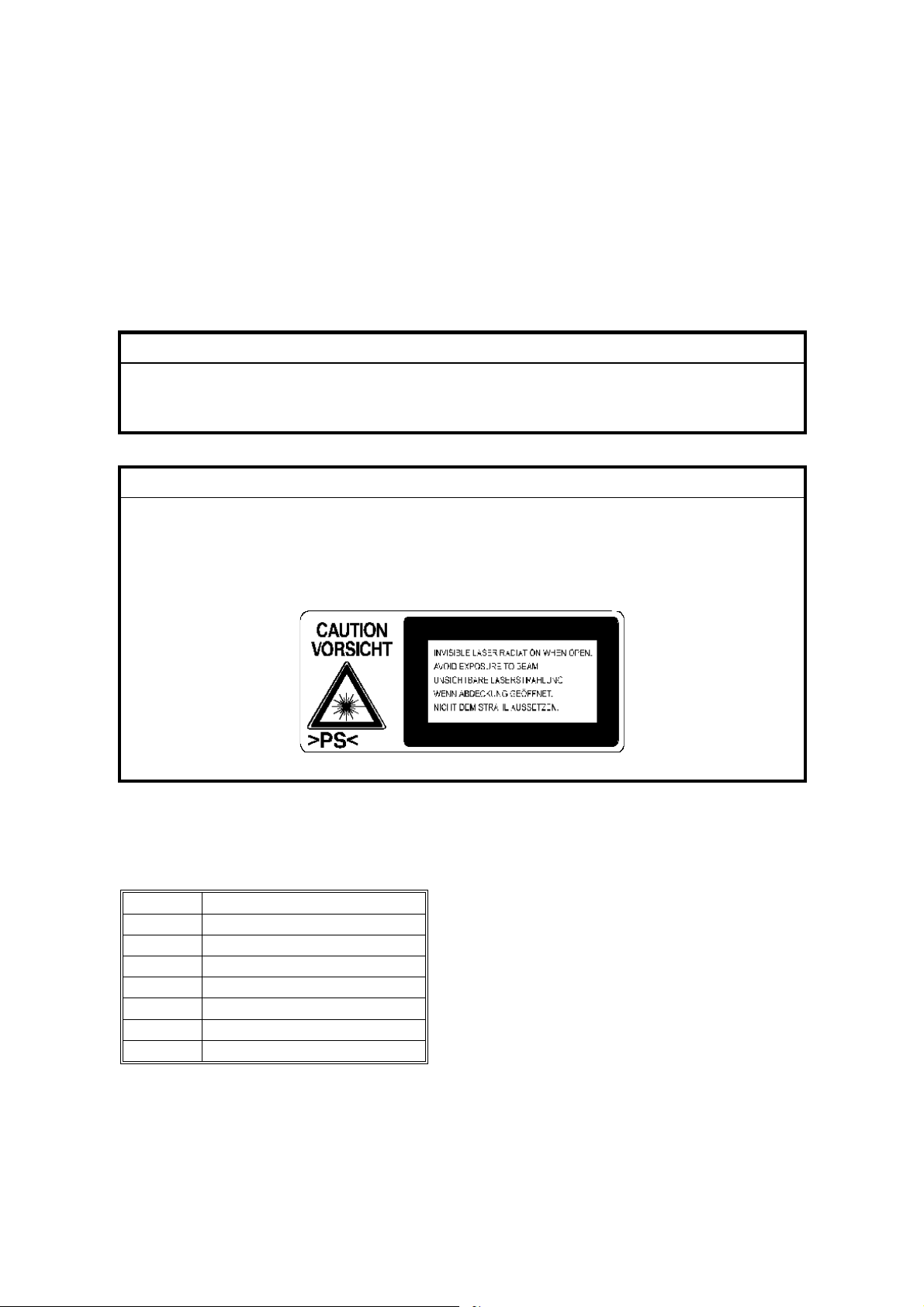
LASER SAFETY
The Center for Devices and Radiological Health (CDRH) prohibits the repair of
laser-based optical units in the field. The optical housing unit can only be repaired
in a factory or at a location with the requisite equipment. The laser subsystem is
replaceable in the field by a qualified Customer Engineer. The laser chassis is not
repairable in the field. Customer engineers are therefore directed to return all
chassis and laser subsystems to the factory or service depot when replacement of
the optical subsystem is required.
!
WARNING
Use of controls not specified in this manual, or performance of
adjustments or procedures not specified in this manual, may result in
hazardous radiation exposure.
!
WARNING FOR LASER UNIT
WARNING: Turn off the main switch before atte mpting any of the
procedures in the Laser Unit section. Laser beams can cause
serious damage to eyes.
CAUTION MARKING:
Symbols and Abbreviations
This manual uses the symbols and abbrev i ati ons show n below.
Symbol Meaning
☛
!
"
#
SEF Short Edge Feed
LEF Long Edge Feed
$
"See," "Refer to"
Clip ring
Screw
Connector
Core Technology manual
2

TABLE OF CONTENTS
1 INSTALLATION ........................................................................... 1-1
1.1 INSTALLATION REQUIREMENTS ...........................................................1-1
1.1.1 ENVIRONMENT ...............................................................................1-1
1.1.2 MACHINE LEVEL.............................................................................1-2
1.1.3 MINIMUM OPERATIONAL SPACE REQUIREMENTS ....................1-2
1.1.4 POWER REQUIREMENTS ..............................................................1-3
1.2 COPIER.....................................................................................................1-4
1.2.1 ACCESSORY CHECK......................................................................1-4
1.2.2 INSTALLATION PROCEDURE ........................................................1-4
Initial Programming: Faxless models (B044, B045) .............................1-8
Initial Programming: Fax-equipped models (B046, B049)....................1-8
1.3 PAPER TRAY UNIT ................................................................................1-10
1.3.1 ACCESSORY CHECK....................................................................1-10
1.3.2 INSTALLATION PROCEDURE ......................................................1-10
1.4 PAPER TRAY UNIT HEATER.................................................................1-12
1.4.1 ACCESSORY CHECK....................................................................1-12
1.4.2 INSTALLATION PROCEDURE ......................................................1-12
1.5 DOCUMENT FEEDER ............................................................................1-17
1.5.1 ACCESSORY CHECK....................................................................1-17
1.5.2 INSTALLATION PROCEDURE ......................................................1-17
1.6 DIMM.......................................................................................................1-21
1.6.1 INSTALLATION PROCEDURE ......................................................1-21
2 PREVENTIVE MAINTENANCE SCHEDULES............................. 2-1
2.1 PM TABLES ..............................................................................................2-1
2.2 HOW TO CLEAR THE PM COUNTER......................................................2-2
3 REPLACEMENT AND ADJUSTMENT......................................... 3-1
3.1 PRECAUTIONS.........................................................................................3-1
3.1.1 GENERAL ........................................................................................3-1
3.1.2 LITHIUM BATTERIES ......................................................................3-1
3.1.3 PCU (PHOTOCONDUCTOR UNIT) .................................................3-1
3.1.4 TRANSFER ROLLER.......................................................................3-1
3.1.5 SCANNER UNIT...............................................................................3-2
3.1.6 LASER UNIT ....................................................................................3-2
3.1.7 FUSING UNIT...................................................................................3-2
3.1.8 PAPER FEED...................................................................................3-2
3.1.9 IMPORTANT ....................................................................................3-3
3.2 SPECIAL TOOLS AND LUBRICANTS ......................................................3-3
3.3 EXTERIOR COVER AND OPERATION PANEL .......................................3-4
3.3.1 PLATEN COVER..............................................................................3-4
3.3.2 REAR COVER..................................................................................3-4
3.3.3 COPY TRAY.....................................................................................3-5
3.3.4 SCALE PLATE (B044 AND B045 ONLY) .........................................3-5
3.3.5 LEFT COVER ...................................................................................3-6
i

3.3.6 RIGHT COVER.................................................................................3-6
3.3.7 FRONT LEFT COVER AND OPERATION PANEL ..........................3-6
3.3.8 FRONT RIGHT COVER ...................................................................3-6
3.3.9 RIGHT DOOR...................................................................................3-7
3.3.10 BYPASS TRAY (B044 AND B046 ONLY) ......................................3-7
3.3.11 PLATEN COVER SENSOR............................................................3-8
3.4 SCANNER SECTION ................................................................................3-9
3.4.1 EXPOSURE GLASS.........................................................................3-9
Non-DF machines.................................................................................3-9
DF-equipped machines.........................................................................3-9
3.4.2 LENS BLOCK .................................................................................3-10
3.4.3 EXPOSURE LAMP, LAMP STABILIZER BOARD ..........................3-10
3.4.4 SCANNER MOTOR........................................................................3-11
3.4.5 SCANNER HP SENSOR................................................................3-11
3.4.6 SCANNER ALIGNMENT ADJUSTMENT .......................................3-12
3.5 FUSING...................................................................................................3-13
3.5.1 FUSING UNIT.................................................................................3-13
3.5.2 EXIT SENSOR ...............................................................................3-13
3.5.3 HOT ROLLER STRIPPER PAWLS ................................................3-14
3.5.4 HOT ROLLER & FUSING LAMP ....................................................3-15
3.5.5 THERMOFUSE, THERMOSWITCH, AND THERMISTOR.............3-15
3.5.6 PRESSURE ROLLER.....................................................................3-16
3.6 PCU.........................................................................................................3-17
3.7 TONER SUPPLY CLUTCH .....................................................................3-18
3.8 PAPER FEED SECTION.........................................................................3-19
3.8.1 PAPER FEED ROLLER AND FRICTION PAD...............................3-19
3.8.2 PAPER END SENSOR...................................................................3-19
3.8.3 REGISTRATION SENSOR.............................................................3-20
3.8.4 BYPASS PAPER END SENSOR (B044 AND B046 ONLY) ...........3-20
3.8.5 BYPASS FEED ROLLER (B044 AND B046 ONLY) .......................3-21
3.8.6 BYPASS FEED CLUTCH (B044 AND B046 ONLY).......................3-22
3.8.7 BYPASS FRICTION PAD (B044 AND B046 ONLY).......................3-22
3.8.8 REGISTRATION CLUTCH .............................................................3-22
3.8.9 PAPER FEED CLUTCH .................................................................3-23
3.9 IMAGE TRANSFER.................................................................................3-24
3.9.1 IMAGE TRANSFER ROLLER ........................................................3-24
3.9.2 ID (IMAGE DENSITY) SENSOR ....................................................3-24
3.9.3 DISCHARGE PLATE......................................................................3-25
3.10 FUNCTION CONTROL UNIT (FCU) .....................................................3-25
3.11 LASER UNIT .........................................................................................3-27
3.11.1 LOCATION OF “CAUTION” DECAL ............................................3-27
3.11.2 PSU BRACKET ............................................................................3-28
3.11.3 LASER UNIT ................................................................................3-29
3.11.4 LD UNIT........................................................................................3-29
3.11.5 POLYGON MIRROR MOTOR ......................................................3-29
ii

3.12 OTHER REPLACEMENTS....................................................................3-30
3.12.1 QUENCHING LAMP.....................................................................3-30
3.12.2 HIGH-VOLTAGE POWER SUPPLY BOARD ...............................3-30
3.12.3 PSU ..............................................................................................3-30
3.12.4 MAIN MOTOR ..............................................................................3-31
3.12.5 EXHAUST FAN ............................................................................3-31
3.13 COPY IMAGE ADJUSTMENTS: PRINTING/SCANNING .....................3-32
3.13.1 PRINTING ....................................................................................3-32
Registration - Leading Edge/Side-to-Side...........................................3-32
Blank Margin.......................................................................................3-33
Main-Scan Magnification.....................................................................3-33
3.13.2 SCANNING...................................................................................3-34
Registration: Platen Mode...................................................................3-34
Magnification.......................................................................................3-34
Standard White Density Adjustment ...................................................3-35
3.13.3 DF IMAGE ADJUSTMENT ...........................................................3-36
Registration and Blank Margin............................................................3-36
Sub-scan Magnification.......................................................................3-36
4 TROUBLESHOOTING ................................................................. 4-1
4.1 SERVICE CALL CONDITIONS .................................................................4-1
4.1.1 SUMMARY .......................................................................................4-1
4.1.2 SC CODE DESCRIPTIONS .............................................................4-2
4.2 ELECTRICAL COMPONENT DEFECTS ..................................................4-7
4.2.1 SENSOR/SWITCH OPEN ERRORS................................................4-7
4.3 BLOWN FUSE CONDITIONS ...................................................................4-7
4.4 DUMPING THE FUSER TEMPERATURE LOG........................................4-8
5 SERVICE TABLES....................................................................... 5-1
5.1 USING SERVICE PROGRAM MODE .......................................................5-1
Accessing SP Mode..............................................................................5-1
Accessing Copy Mode from within SP Mode ........................................5-1
How to Select a Program Number ........................................................5-2
To Input a Value or Setting ...................................................................5-2
5.1.1 SP MODE TABLES ..........................................................................5-3
SP1-XXX (Feed) ...................................................................................5-3
SP2-XXX (Drum)...................................................................................5-4
SP4-XXX (Scanner) ..............................................................................5-9
SP5-XXX (Mode) ................................................................................5-14
SP6-XXX (Peripherals) .......................................................................5-18
SP7-XXX (Data Log)...........................................................................5-19
5.1.2 TEST PATTERN PRINTING (SP5-902) .........................................5-23
5.1.3 INPUT CHECK (SP5-803)..............................................................5-24
Input Check Table...............................................................................5-24
5.1.4 OUTPUT CHECK (SP5-804)..........................................................5-25
Input Check Table...............................................................................5-25
5.1.5 SMC PRINTING (SP5-992) ............................................................5-26
5.1.6 MEMORY ALL CLEAR (SP5-801)..................................................5-27
5.1.7 FREE RUNS...................................................................................5-28
iii

5.1.8 PROGRAM UPLOAD/DOWNLOAD ...............................................5-29
Program Download (SP5-827)............................................................5-29
Program Upload (SP5-826) ................................................................5-31
5.1.9 SRAM DATA UPLOAD/DOWNLOAD.............................................5-32
SRAM Data Upload (SP5-824) ...........................................................5-32
SRAM Data Download (SP5-825).......................................................5-33
5.1.10 SERIAL NUMBER INPUT (SP5-811) ...........................................5-33
5.1.11 ID SENSOR ERROR ANALYSIS (SP2-221) ................................5-34
5.1.12 MEMORY READ/WRITE ..............................................................5-35
5.2 USER TOOLS .........................................................................................5-36
5.2.1 HOW TO ENTER AND EXIT USER TOOLS ..................................5-36
5.2.2 USER TOOLS TABLE ....................................................................5-36
System Settings Table........................................................................5-36
Copy Features Table ..........................................................................5-36
6 DETAILED SECTION DESCRIPTIONS ....................................... 6-1
6.1 OVERVIEW ...............................................................................................6-1
6.1.1 COMPONENT LAYOUT...................................................................6-1
6.2 PAPER PATH............................................................................................6-5
6.3 DRIVE LAYOUT ........................................................................................6-6
6.4 BLOCK DIAGRAM: PCBS AND COMPONENTS......................................6-7
6.5 MAIN PCBS...............................................................................................6-8
6.5.1 FCU (FUNCTION/FACSIMILE CONTROL UNIT).............................6-8
SPC2 ....................................................................................................6-9
VPL (Video Processing LSI) .................................................................6-9
CIOP (Communications and I/O Processing)........................................6-9
FROM (Flash ROM) – 2MB ..................................................................6-9
DRAM – 8MB.......................................................................................6-9
SRAM – 128K .......................................................................................6-9
3V/5V Converter ...................................................................................6-9
Energy-Save Switching.........................................................................6-9
Reset/Backup Circuit ..........................................................................6-10
SAF Backup........................................................................................6-10
Analog Processing Circuit...................................................................6-10
Modem................................................................................................6-10
Speaker Driver....................................................................................6-10
Heater Control ....................................................................................6-10
Video Processing Circuit.....................................................................6-10
Power Pack Control ............................................................................6-10
Scanner Driver....................................................................................6-10
Plotter Driver.......................................................................................6-10
6.5.2 SBU (SENSOR BOARD UNIT).......................................................6-11
Buffer ..................................................................................................6-11
CCD ....................................................................................................6-11
Amplifier..............................................................................................6-11
6.5.3 NCU (NETWORK CONTROL UNIT) ..............................................6-12
North America version ........................................................................6-12
Europe/Asia version............................................................................6-12
iv

6.6 COPY PROCESS OVERVIEW ...............................................................6-13
6.7 SCANNING..............................................................................................6-15
6.7.1 OVERVIEW ....................................................................................6-15
6.7.2 SCANNER DRIVE ..........................................................................6-16
6.8 IMAGE PROCESSING ............................................................................6-17
6.8.1 OVERVIEW ....................................................................................6-17
6.8.2 IMAGE PROCESSING PATH.........................................................6-18
6.8.3 ORIGINAL MODES ........................................................................6-19
Original Modes: Copying....................................................................6-20
6.8.4 IMAGE PROCESSING STEPS FOR EACH MODE .......................6-21
6.8.5 MODE ADJUSTMENTS .................................................................6-22
To customize... ...................................................................................6-22
Default plotter customization settings for each mode... ......................6-23
6.9 LASER EXPOSURE................................................................................6-24
6.9.1 OVERVIEW ....................................................................................6-24
6.9.2 LD SAFETY SWITCHES ................................................................6-25
6.10 PHOTOCONDUCTOR UNIT (PCU) ......................................................6-26
6.10.1 OVERVIEW ..................................................................................6-26
6.10.2 DRUM DRIVE...............................................................................6-27
6.11 DRUM CHARGE ...................................................................................6-28
6.11.1 OVERVIEW ..................................................................................6-28
6.11.2 CHARGE ROLLER VOLTAGE CORRECTION............................6-29
Correction for Ambient Environment...................................................6-29
6.11.3 CHARGE ROLLER CLEANING....................................................6-30
6.11.4 DETECTION OF A NEW PCU......................................................6-31
At time of copier installation................................................................6-31
When a replacement PCU is installed.................................................6-31
6.12 DEVELOPMENT ...................................................................................6-32
6.12.1 OVERVIEW ..................................................................................6-32
6.12.2 DEVELOPMENT BIAS .................................................................6-33
6.12.3 TONER SUPPLY..........................................................................6-34
Toner-Bottle Models (B044 and B046)................................................6-34
Toner Hopper Magazine (B045 and B049) .........................................6-35
6.12.4 TONER DENSITY CONTROL ......................................................6-36
Overview.............................................................................................6-36
Reference Voltage ..............................................................................6-36
Toner Density Sensor Initial Setting....................................................6-36
Toner Concentration Measurement ....................................................6-37
Vsp/Vsg Detection ..............................................................................6-37
Calculation of Vref ..............................................................................6-37
Toner Supply Determination ...............................................................6-37
Toner Clutch ON Time........................................................................6-37
6.12.5 TONER SUPPLY IF SENSOR READING IS ABNORMAL ...........6-38
ID Sensor............................................................................................6-38
TD Sensor...........................................................................................6-38
v

6.12.6 DETECTION OF TONER NEAR END AND TONER END ...........6-38
Toner Near End detected when either of the following occurs............6-38
Toner End detected when any of the following occurs........................6-38
6.13 DRUM CLEANING AND TONER RECYCLING.....................................6-39
6.14 PAPER FEED........................................................................................6-40
6.14.1 OVERVIEW ..................................................................................6-40
6.14.2 PAPER FEED DRIVE MECHANISM ............................................6-41
From Paper Tray.................................................................................6-41
From 100-Sheet Bypass Tray (B044, B046).......................................6-41
From 1-Sheet Bypass Tray (B045, B049)...........................................6-41
6.14.3 PAPER FEED AND SEPARATION ..............................................6-42
6.14.4 PAPER LIFT MECHANISM ..........................................................6-42
PAPER END DETECTION .................................................................6-43
Main Tray............................................................................................6-43
100-Sheet Bypass Tray (B044, B046) ................................................6-43
6.14.5 PAPER REGISTRATION..............................................................6-43
6.15 IMAGE TRANSFER AND PAPER SEPARATION .................................6-44
6.15.1 OVERVIEW ..................................................................................6-44
6.15.2 IMAGE TRANSFER CURRENT TIMING......................................6-45
6.15.3 TRANSFER ROLLER CLEANING................................................6-46
6.16 IMAGE FUSING AND PAPER EXIT......................................................6-47
6.16.1 OVERVIEW ..................................................................................6-47
6.16.2 FUSING DRIVE AND RELEASE MECHANISM ...........................6-47
6.16.3 PRESSURE ROLLER...................................................................6-48
6.16.4 PRESSURE RELEASE ................................................................6-48
Separation ..........................................................................................6-48
6.16.6 FUSING TEMPERATURE CONTROL..........................................6-49
Overview.............................................................................................6-49
Fusing Temperature Control for Thick Paper......................................6-49
6.16.7 OVERHEAT PROTECTION .........................................................6-49
6.17 ENERGY SAVER MODES ....................................................................6-50
6.17.1 MODE TRANSITIONS..................................................................6-50
6.17.2 SYSTEM SETTINGS....................................................................6-51
6.17.3 LOW POWER MODE LEVELS.....................................................6-51
6.17.4 AUTO-OFF LEVEL .......................................................................6-51
6.17.5 TRANSITION OPERATION..........................................................6-51
vi

PAPER TRAY UNIT (B421)
1 OVERALL MACHINE INFORMATION...................................B421-1
1.1 MECHANICAL COMPONENT LAYOUT ............................................ B421-1
1.2 ELECTRICAL COMPONENT LAYOUT.............................................. B421-1
1.3 DRIVE LAYOUT ................................................................................. B421-2
1.4 OVERALL ELECTRICAL CIRCUIT .................................................... B421-2
1.5 DETAILED DESCRIPTIONS.............................................................. B421-3
1.5.1 PAPER FEED AND SEPARATION ........................................... B421-3
1.6 PAPER LIFT MECHANISM................................................................ B421-3
1.7 PAPER END DETECTION................................................................. B421-4
1.8 SIDE AND END FENCES .................................................................. B421-5
2 REPLACEMENT AND ADJUSTMENT...................................B421-6
2.1 FEED ROLLER AND FRICTION PAD................................................ B421-6
2.2 REMOVING THE PAPER TRAY UNIT FROM THE COPIER............. B421-6
If Optional Tray Heater Is Not Installed.......................................... B421-6
If Optional Tray Heater Is Installed ................................................ B421-6
2.3 SENSORS.......................................................................................... B421-7
2.4 DRIVE SECTION................................................................................ B421-8
2.4.1 DRIVE BLOCK .......................................................................... B421-8
2.4.2 PAPER FEED MOTOR.............................................................. B421-8
2.4.3 PAPER FEED CLUTCH ............................................................ B421-9
2.4.4 TRAY MAIN BOARD ( 2.4.1) ..................................................... B421-9
DOCUMENT FEEDER (B444)
1 OVERALL INFORMATION ....................................................B444-1
1.1 MECHANICAL COMPONENT LAYOUT ............................................ B444-1
1.2 ELECTRICAL COMPONENT LAYOUT.............................................. B444-2
1.3 DRIVE LAYOUT ................................................................................. B444-3
2 DETAILED SECTION DESCRIPTIONS .................................B444-4
2.1 PICK-UP AND SEPARATION ............................................................ B444-4
2.2 CLUTCH OPERATION....................................................................... B444-4
2.3 TRANSPORT AND EXIT.................................................................... B444-4
2.4 UNIT OPEN SWITCH AND GUIDE OPEN SENSOR......................... B444-5
2.5 OVERALL ELECTRICAL CIRCUIT .................................................... B444-5
3 REPLACEMENT AND ADJUSTMENT...................................B444-6
3.1 DF UPPER COVERS ......................................................................... B444-6
3.2 ORIGINAL TABLE .............................................................................. B444-6
3.3 FEED UNIT......................................................................................... B444-6
3.4 DF PICKUP ROLLER......................................................................... B444-7
3.5 DF FEED ROLLER............................................................................. B444-7
vii

3.6 DF SEPARATION ROLLER ............................................................... B444-8
3.7 DF MOTOR ........................................................................................ B444-9
3.8 DF FEED CLUTCH........................................................................... B444-10
3.9 SENSORS........................................................................................ B444-10
3.10 DF EXPOSURE GLASS................................................................. B444-11
3.11 DF CONNECTION BOARD............................................................ B444-11
SPECIFICATIONS
1 GENERAL SPECIFICATIONS..............................................................SPEC-1
2 MACHINE CONFIGURATION.............................................................. SPEC-5
3 OPTIONAL EQUIPMENT..................................................................... SPEC-6
ADF .................................................................................................. SPEC-6
PAPER TRAY UNIT ........................................................................... SPEC-6
viii
24 July, 2001 INSTALLATION REQUIREMENTS
1. INSTALLATION
!!!!
CAUTION
Before installing options, please do the following:
1. If there is a fax unit on the machine, print out all messages stored in the
memory, all user-programmed items, and a system parameter list.
2. If there is a printer option on the machine, print out all data in the
printer buffer.
3. Turn off the main switch and disconnect the power cord, the telephone
line, and the network cable.
1.1 INSTALLATION REQUIREMENTS
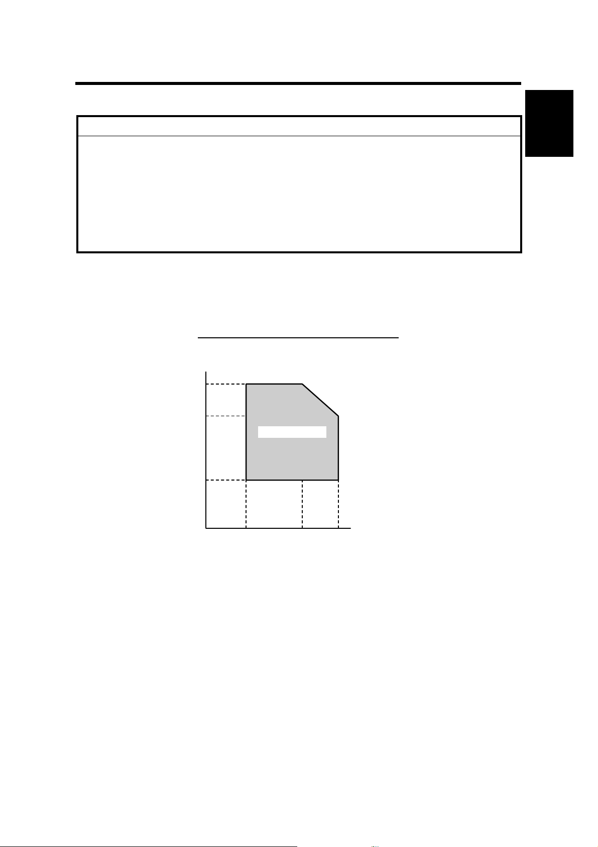
1.1.1 ENVIRONMENT
–Temperature and Humidity Chart–
Installation
Humidity
80%
54%
Operation range
15%
10°C
(50°F)
27°C
(80.6°F)
(89.6°F)
32°C
Temperature
B046I512.WMF
1. Temperature Range: 10°C to 32°C (50°F to 89.6°F)
2. Humidity Range: 15% to 80% RH
3. Ambient Illumination: Less than 1,500 lux (Do not expose to direct sunlight.)
4. Ventilation: Room air should turn over at least 3 times/hr/person
5. Ambient Dust Less than 0.1 mg/m
3
6. Do not install the machine where it will be exposed to direct sunlight or to direct
airflow (from a fan, air conditioner , air clean er, etc .) .
7. Do not install the machine where it will be exposed to corrosive gas.
8. Place the machine on a firm and level base.
9. Do not install the machine where it may be subjected to strong vibration.
1-1

INSTALLATION REQUIREMENTS 24 July, 2001
1.1.2 MACHINE LEVEL
Front to back: Within 5 mm (0.2") of level
Right to left: Within 5 mm (0.2") of level
1.1.3 MINIMUM OPERATIONAL SPACE REQUIREMENTS
Place the machine near the power source, providing clearance as shown.
[C]
[D]
[B]
450 mm (17.7")
A: Front > 750 mm (29.6")
[A]
B: Left > 100 mm (3.9 ")
C: Rear > 105 mm (4.1")
D: Right > 230 mm (9.0")
468 mm (18.4")
B046I130.WMF
NOTE: 1) The 750-mm front space indicated above is sufficient to allow the paper
tray to be pulled out. Additional space is required to allow an operator to
stand at the front of the machine.
2) Actual minimum space requirement for left, rear, and right sides is
10mm (0.4") each, but note that this will not allow room for opening of
the bypass tray, right door, platen cover, or ADF unit.
1-2

24 July, 2001 INSTALLATION REQUIREMENTS
1.1.4 POWER REQUIREMENTS
!
CAUTION
1. Make sure that the wall outlet is near the machine and easily accessible.
After completing installation, make sure the plug fits firmly into the
outlet.
2. Avoid multi-wiring.
3. Be sure to ground the machine.
Input voltage:
North America: 110 – 120 V, 50/60 Hz, 10 A
Europe: 220 – 240 V, 50/60 Hz, 5 A
Image quality guaranteed at rated voltage ± 10%.
Operation guaranteed at rated voltage ± 15%.
Installation
1-3
COPIER 24 July, 2001
1.2 COPIER
1.2.1 ACCESSORY CHECK
Check that you have the accessories indicated below. Note that accessories vary
according to model and location.
No. Description Q’ty
1 Copier Operating Instructio ns (-17, -26, -29) 1
2 EU safety sheet (-22, -24, -26, -27) 1
3 NECR (-17, -27, -29) 1
4 Paper-size decals 1 set
5 Energy Star seal (-26) 1
6 Branding plaques (-22) 1 set
7 Brand decals 1 set
8 Handset bracket (B046, B049) 1
1.2.2 INSTALLATION PROCEDURE
!
CAUTION
Make sure that the copier remains unplugged during installation.
[A]
B046I101.WMF
[B]
B046I124.WMF
1. Remove the strips of tape.
2. Remove the bag [A] holding the included accessories.
3. Remove the spacing wedge [B].
1-4
24 July, 2001 COPIER
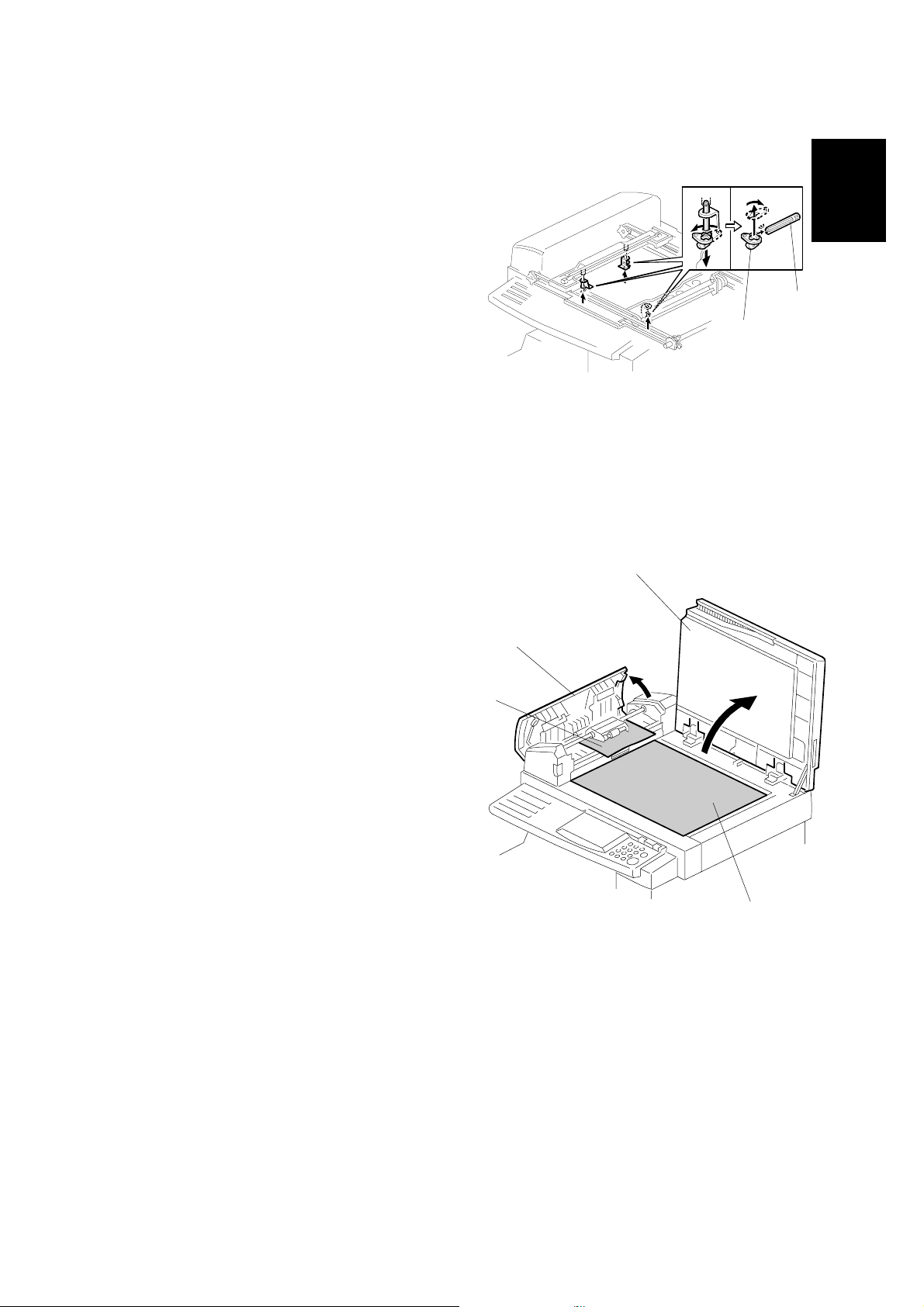
4. Remove the 3 scanner lock pins. (A
tag is hanging from each pin.) To
remove: Grasp the base of the pin [A],
turn 90 degrees, and pull down and
out.
[B]
[A]
Installation
5. Remove the tags from the pins. Then
break each pin off of its base [A],
discard the pin part [B], and set each
base [A] back into its original hole,
turning it 90° to lock it into place. (Be
sure to do this for all three pins.)
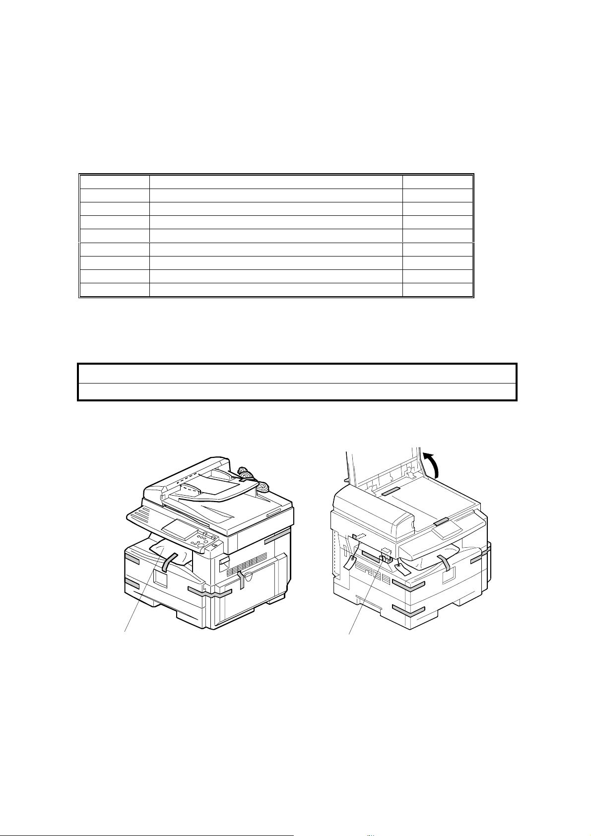
6. If installing a DF-equipped model
(B046 or B049): Raise the DF upper
guide [C] and remove the protective
paper [D] at the feed unit. Then lower
the guide.
7. Open the platen cover [E] and remove
the protective paper [F] covering the
exposure glass. Then close the platen
cover.
B046I106.WMF
[E]
[C]
[D]
1-5
B046I107.WMF
[F]
COPIER 24 July, 2001
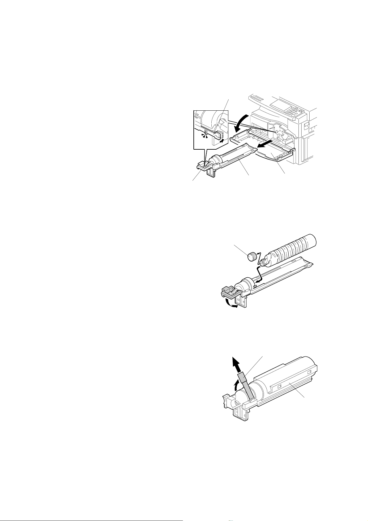
8. Open the front door [A].
9. If installing a toner-bottle model
(B044 or B046):
• Lift lever [B], press in on latch [C]
[C]
and pull the bottle holder [D] out.
(It is not necessary to pull it
completely out of the machine,
however.)
• Take a new bottle of toner, shake
it several times, remove its outer
cap [E], and load as shown. Then
push the bottle holder back into
the machine, and press the latch
[B]
[D]
[A]
down to lock it.
B046I112.WMF
If
installi
ng a toner-hopper magazine model
(B045 or B049):
• Shake the magazine several times, then
peel off the paper [F] from a new THM [G],
and load the THM into the machine.
[E]
B046I301.WMF
[F]
[G]
1-6
B046I114.WMF
24 July, 2001 COPIER
10. Remove the foam cushion [A] and pull the
tabbed strips [B] all the way out of the
PCU. Then close the front door.
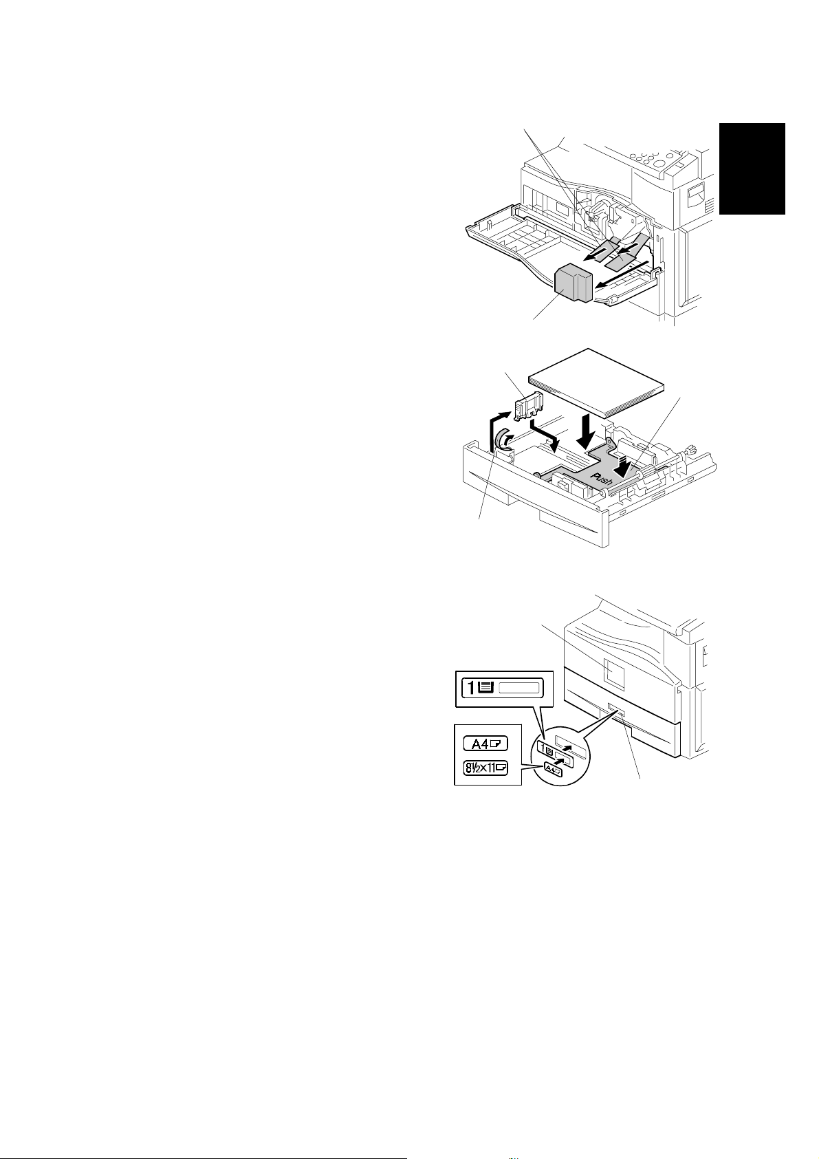
11. Pull open the paper tray, and remove the
tape [C] securing the end fence in the
compartment.
12. Push the bottom plate [D] down, load
paper, and adjust the side fences. If
loading paper shorter than A4, remove
the end fence [E] from its compartment,
set it into the tray, and adjust it to the
correct length.
[B]
Installation
[A]
B046I104.WMF
[E]
[D]
[C]
B046I119.WMF
13. Push the tray back in.
14. Adhere the appropriate branding decal
(not shown) to the center of the front
[F]
door [F], and adhere the tray number
decal and appropriate paper- si ze decal
to the front of the paper tray (at [G]) as
shown.
15. Hong Kong only:
If installing model B046 or B049 in
Hong Kong, you must change the
position of the TB1 jumpe r on the NCU.
Turn to the fax service manual and carry
out steps 4 to 8 of the installation
[G]
B046I515.WMF
procedure (fax service manual, section 1.2.2).
16. Plug in the machine and turn on the main switch.
17. Enter SP mode, and run SP7-825 to initialize the electrical total counter to 0.
NOTE:
1) After selecting SP7-825, enter "1" and then hold down the Original
Type key and press the OK key to initialize the counter. If
initialization is successful, the screen displays "Action comp leted."
2) SP7-825 is effective only once, at time of machine installation .
1-7

COPIER 24 July, 2001
18. Models B046 and B049 only: Access SP5-992 and select "2" to print out a full
SMC report. Confirm that the report shows a "YES" for SP7-801-3.
19. Models B046 and B049 only: Press the On Hook key on the fax operation
panel, and confirm that you hear a dial tone coming from the monitor speaker.
20. Program the required items, as indicated below.
Initial Programming: Faxless models (B044, B045)
Items to Program (Service Level – SP Mode)
Date and time 5-302
Language replacement (Fir mware download) 5-827
*1
*1: See Section 5 for SP-mode usage instructions.
Items to Program (User Level)
Display contrast
Energy saver level (low power mod e)
Reception mode
Other items, as necessary *2
*2
User Tools
User Tools →
System Settings
*2: Refer to the Operating Instructions for details.
Initial Programming: Fax-equipped models (B046, B049)
Items to Program (Service Level – Serv i ce Functions)
Country code (System switch 0F) 01
Protocol requirements (G3 switch 0 B) - E U only 01
PM call (System switch 01 – bit 0) 01
Country code (NCU parameter 0 0) 07
Service station's fax number 09
*3
Function No.
SP No.
*3: See Section 5.1.1 of the fax service manual for information abou t using
service functions.
1-8

24 July, 2001 COPIER
Items to Program (Service Level – SP Mode)
*4
SP No.
Machine's serial number 5-811
Language replacement (Fir mware download) 5-827
PSTN access code (RAM address 4000DB)
PSTN access method (RAM address 4000CD)
7-955
Periodic service call (RAM addresses 40054F to 400553)
*4: See Section 5 for SP-mode usage instructions.
Items to Program (User Administrator Level)
Monitor volume
Display contrast
Date and Time
Reception mode
Fax Header/Own Name/Own No. (TTI/RTI/CSI)
Reports on/off
Country Code (except NA)
Fusing power control during e nergy saver mode System
Language selection Language
Other initial progr amming items *5
*5
User Tools
Fax Features
→ Setup
Key Op. Tools
Settings
Installation
*5: Refer to the Operating Instructions for details.
1-9
PAPER TRAY UNIT 24 July, 2001
1.3 PAPER TRAY UNIT
1.3.1 ACCESSORY CHECK
Confirm that you have the accessories indicated below.
No. Description Q’ty
1 Paper-size decals 1 sheet
2 Installation Procedure (for service person) 1
3 Installation Procedur e (for us er) 1
1.3.2 INSTALLATION PROCEDURE
!
CAUTION
Unplug the main machine's power cord before starting the following
procedure.
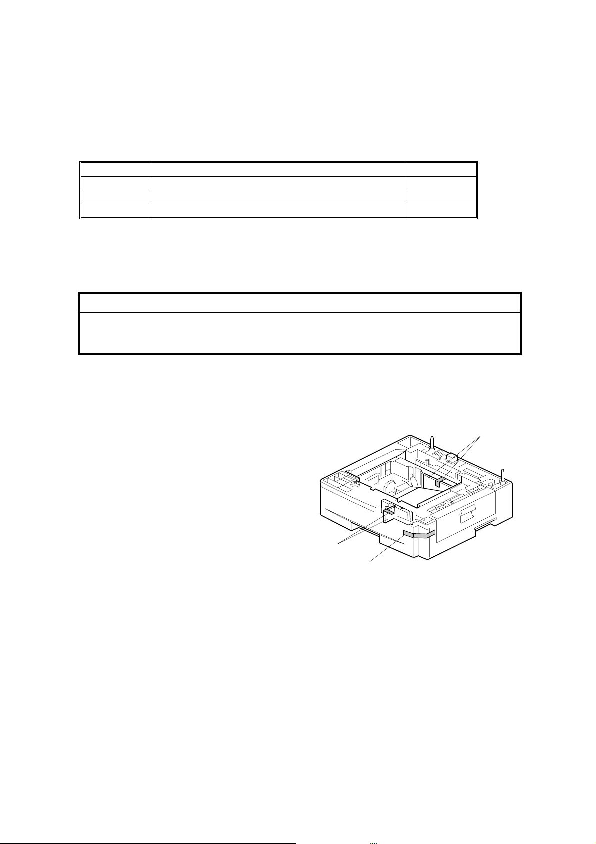
1. Remove the tape at [A], and the tape and cardboard at [B].
2. Pull the paper tray part way out of the unit, remove the tape and cardboard at
[C], and push the tray back in.
[B]
[C]
[A]
B046I516.WMF
1-10
24 July, 2001 PAPER TRAY UNIT
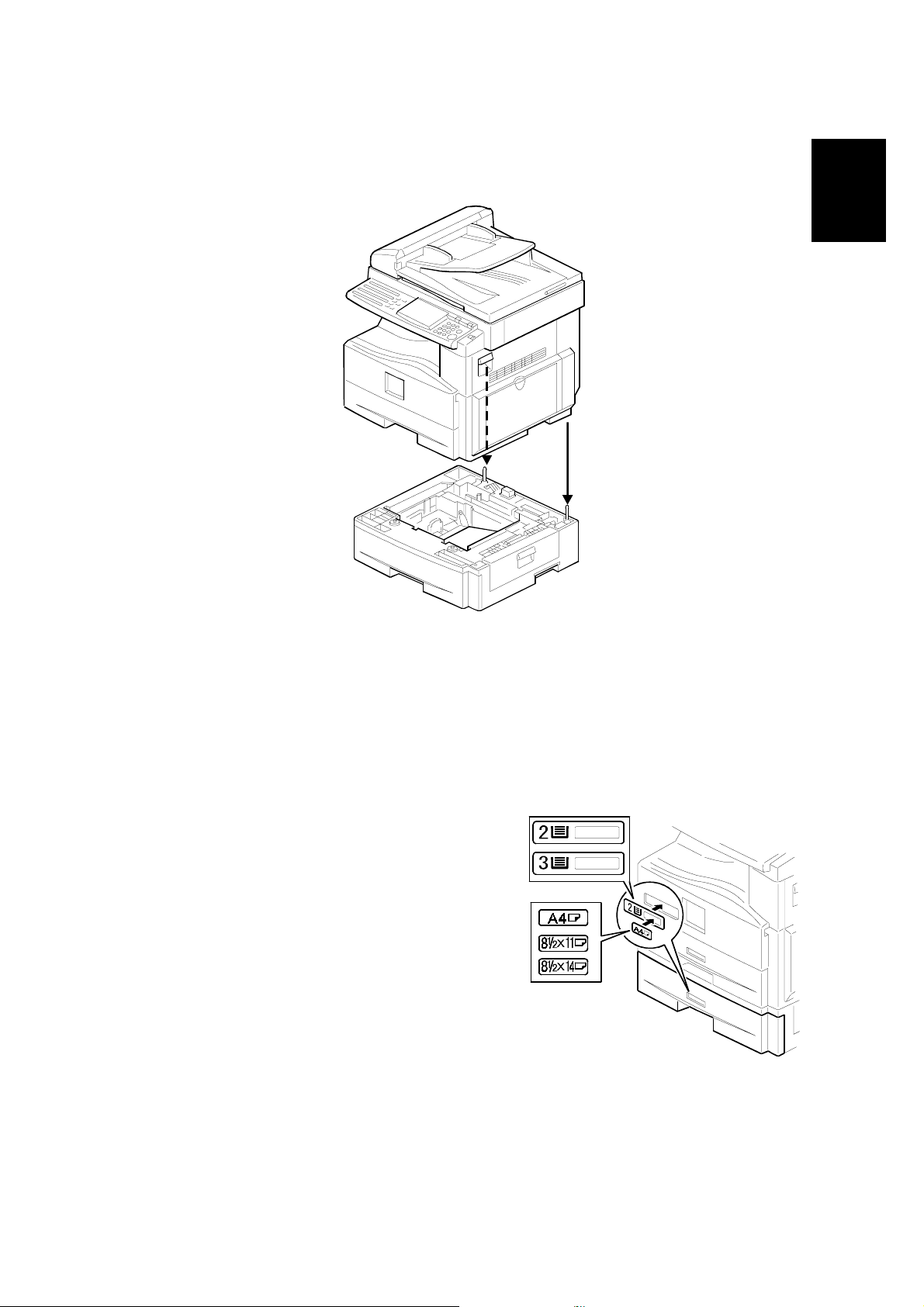
3. Set the machine onto the paper tray unit.
Installation
B046I527.WMF
4. Remove the paper tray from the paper tray unit.
5. Load paper into the paper tray. Adjust the side and end fences as necessary. If
loading 8
"x 14" paper, remove the end fence and set it into the special
1/2
compartment.
6. Set the paper tray back into the paper tray unit.
7. Stick on the appropriate tray-number
decal and paper-size decal, at the
locations indicated in the illustration.
B046I517.WMF
1-11

PAPER TRAY UNIT HEATER 24 July, 2001
1.4 PAPER TRAY UNIT HEATER
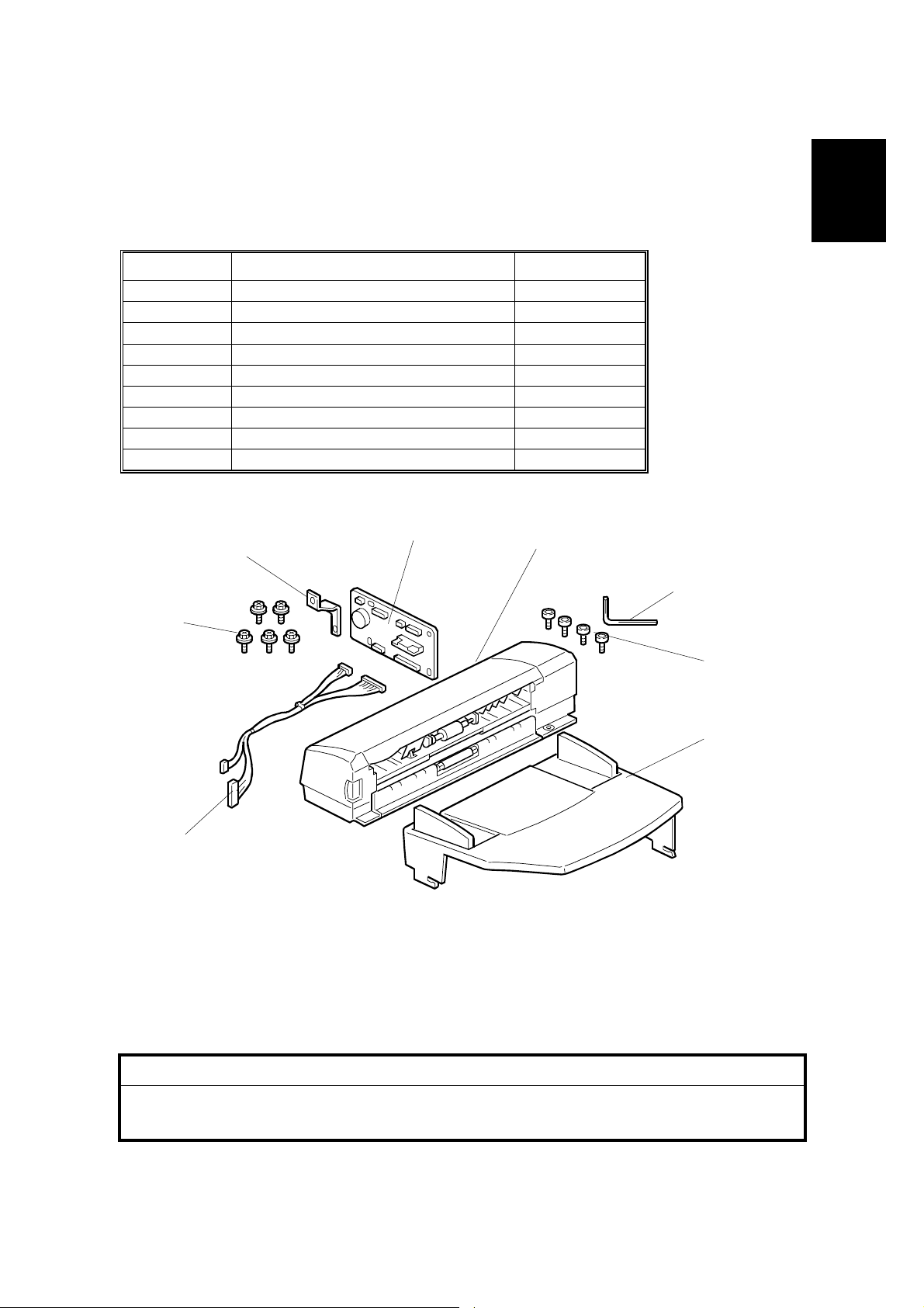
1.4.1 ACCESSORY CHECK
Confirm that you have the accessories indicated below.
No. Description Q’ty
1 Grounding wire 1
2 Relay harness 1
3Clamps 2
4 Ferrite core 1
5 Heater fastening screws 2
6 PTU fastening screws 3
7 Grounding screw 1
8 Decal for copier 1
9 Decal for paper unit 1
10 Tie wrap 1
1
10
9
8
1.4.2 INSTALLATION PROCEDURE
2
3
4
5
6
7
B046I518.WMF
!
CAUTION
Unplug the main machine's power cord before starting the following
procedure.
1. If the paper tray unit is already installed, uninstall it by lifting the copier off of it.
(Refer to illustrations for Procedure 1.3.2, above.)
2. Remove both paper trays—the one from the copier, and the one from the
paper tray unit.
1-12
24 July, 2001 PAPER TRAY UNIT HEATER
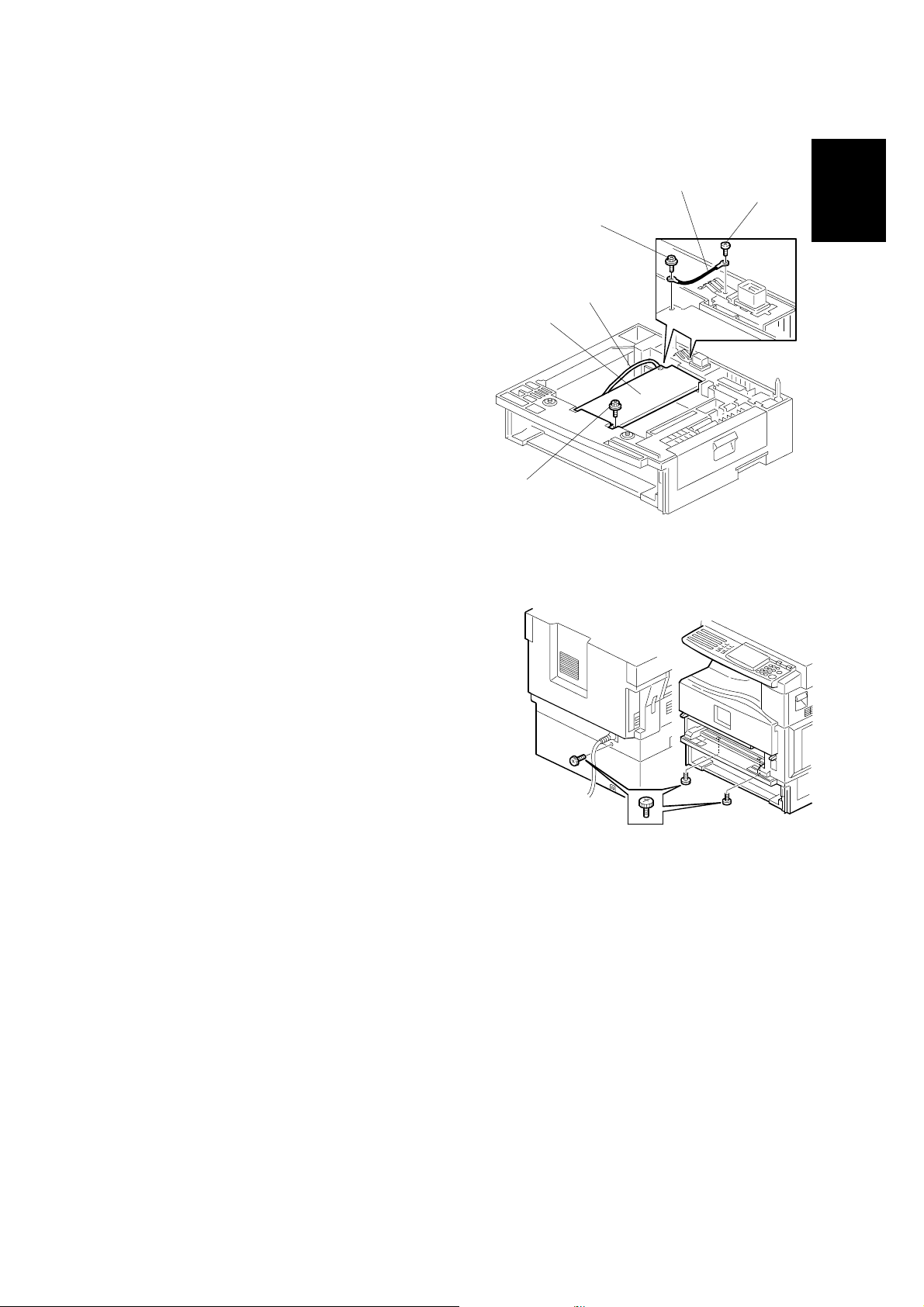
3. Remove the ground screw [A] at the rear of the paper tray unit.
4. Fasten the heater [B] and the supplied
ground wire [C] to the pa per tray unit
with 3 screws as shown. Note that [A]
is the grounding screw you removed at
Step 3 (returned to its original hole),
and [D] and [E] are the two supplied
heater fastening screws.
NOTE: Be sure to position the ground
wire [C] and heater harness [F]
so that they will be out of the
way of the copier when you set
it onto the paper tray unit.
5. Set the copier onto the paper tray unit.
6. Screw the paper tray unit into place using
three supplied PTU fastening screws.
[E]
[B]
[F]
[D]
[C]
[A]
Installation
B046I519.WMF
1-13
B046I500.WMF
PAPER TRAY UNIT HEATER 24 July, 2001
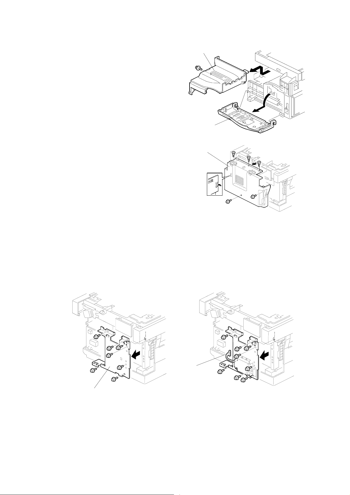
7. Open the front door [A] and remove the
copy tray [B] (!×1). Then close the
front door.
8. Remove the rear cover [C] (! x 5).
[B]
[A]
B046I501.WMF
[C]
B046I502.WMF
9. Remove the FCU cover plate [D] (7 screws on faxless machines, 8 screws on
fax-equipped machines) .
NOTE: On fax-equipped machines, detach the NCU connector [E] first.
Faxless machines: Fax-equipped machines:
[E]
[D]
B046I503.WMF
B046I504.WMF
1-14
24 July, 2001 PAPER TRAY UNIT HEATER
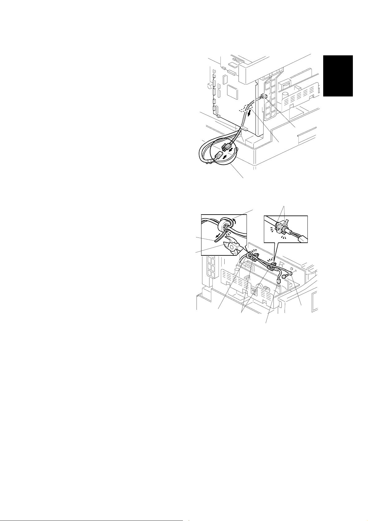
10. Pass the heater's harness through the
hole [A] at the rear of the copier.
11. Pass relay harness [B] through the
circular opening at [C] (at the rear of
[A]
the PSU board bracket), and then
through the hole at [A]. Then connect
[B]
the relay harness to the heater's
harness [D].
[C]
Installation
12. Pull the relay harness back into the
copier. Then set the ferrite core [E]
over the relay harness, and push it
back so that it is over the heater's
harness.
13. Wrap the heater's harness once
around the core (see [F]). Adjust so
that the core is located toward the
rear of the copier (at position [E],
behind the rear clamp). Secure the
core into position using the supplied
tie wrap [G].
14. Clip off the excess length of the tie
wrap [H].
[G]
[H]
[E]
[K]
[D]
B046I520.WMF
[L]
[F]
[J]
B046I521.WMF
[I]
15. Connect the relay harness connector [I] to the large connector at the front
center of the PSU board. Screw the ground wire [J] to the PSU board bracket,
using the included grounding screw.
16. Attach the supplied clamps [K] to corresponding holes on the PSU board
bracket, and set the heater harness though the clamps. Position the harness
so that the front clamp is between the two bindings [L] on the harness. Then
fasten the clamps.
1-15
PAPER TRAY UNIT HEATER 24 July, 2001
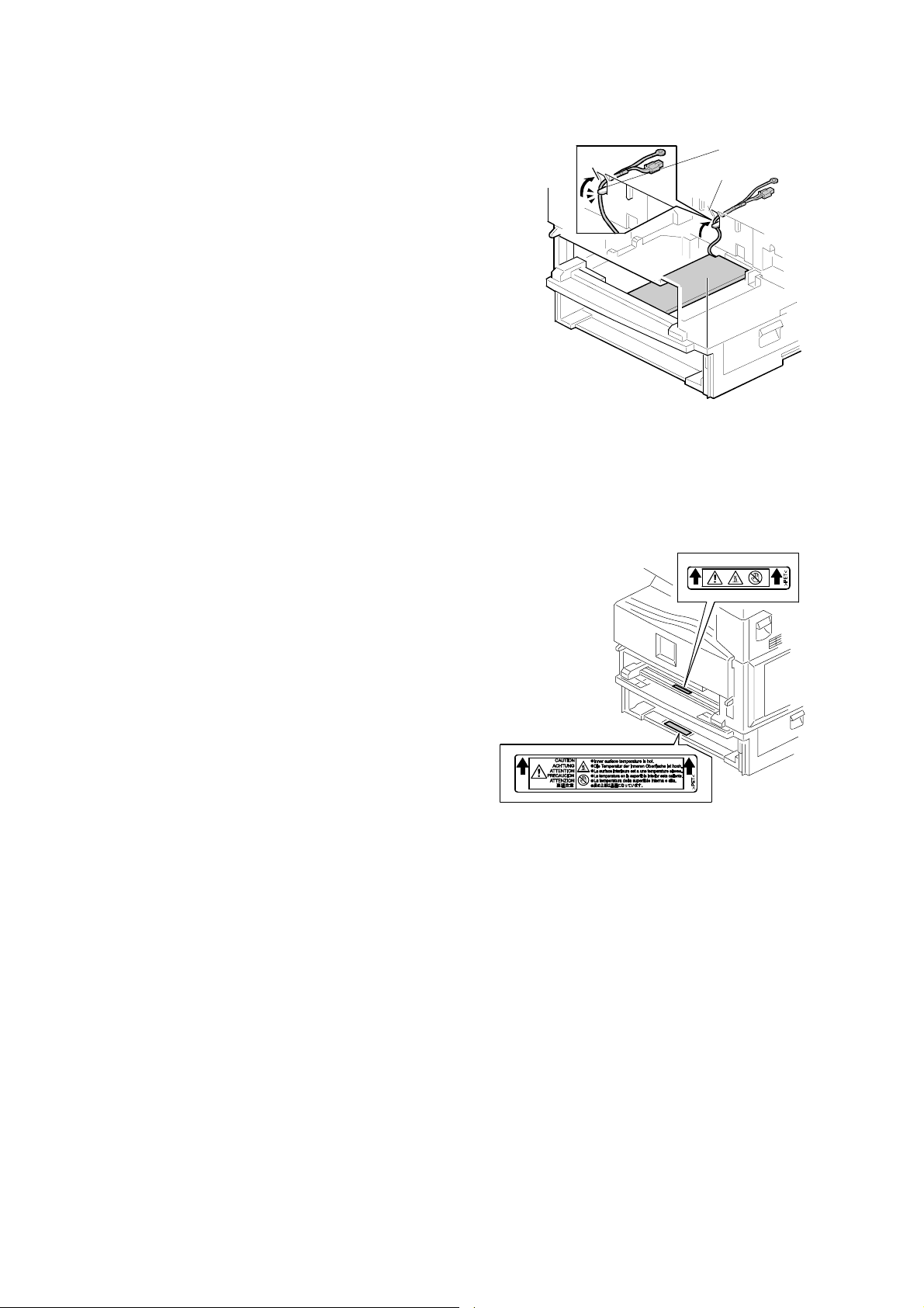
17. Pull the excess length of the heater's
harness out the hole at the rear [A].
NOTE: Be sure that the harness passes to
the side of the grounding plate [B]
at the bottom of the hole. (The front
of the grounding plate must remain
clear.)
18. Arrange the excess harness length so that it sits beneath the
FCU cover plate.
19. Attach the caution decals
to the locations shown in
the illustration.
[B]
[A]
B046I522.WMF
20. Reinsert the paper trays, and reattach the copy tray and the rear cover.
1-16
B046I523.WMF
24 July, 2001 DOCUMENT FEEDER
1.5 DOCUMENT FEEDER
1.5.1 ACCESSORY CHECK
Confirm that you have the components and accessories indicated below.
No. Description Q’ty
1 DF connection board 1
2 DF body 1
3 Hex wrench 1
4Hex screws 4
5 DF original tab le 1
6 Wire harness 1
7 Phillips-head screws 5
8Bracket 1
– Installation Procedure 1
1
8
2
3
7
Installation
4
6
B046I524.WMF
1.5.2 INSTALLATION PROCEDURE
!
CAUTION
Unplug the main machine's power cord before starting the following
procedure.
5
1-17
DOCUMENT FEEDER 24 July, 2001
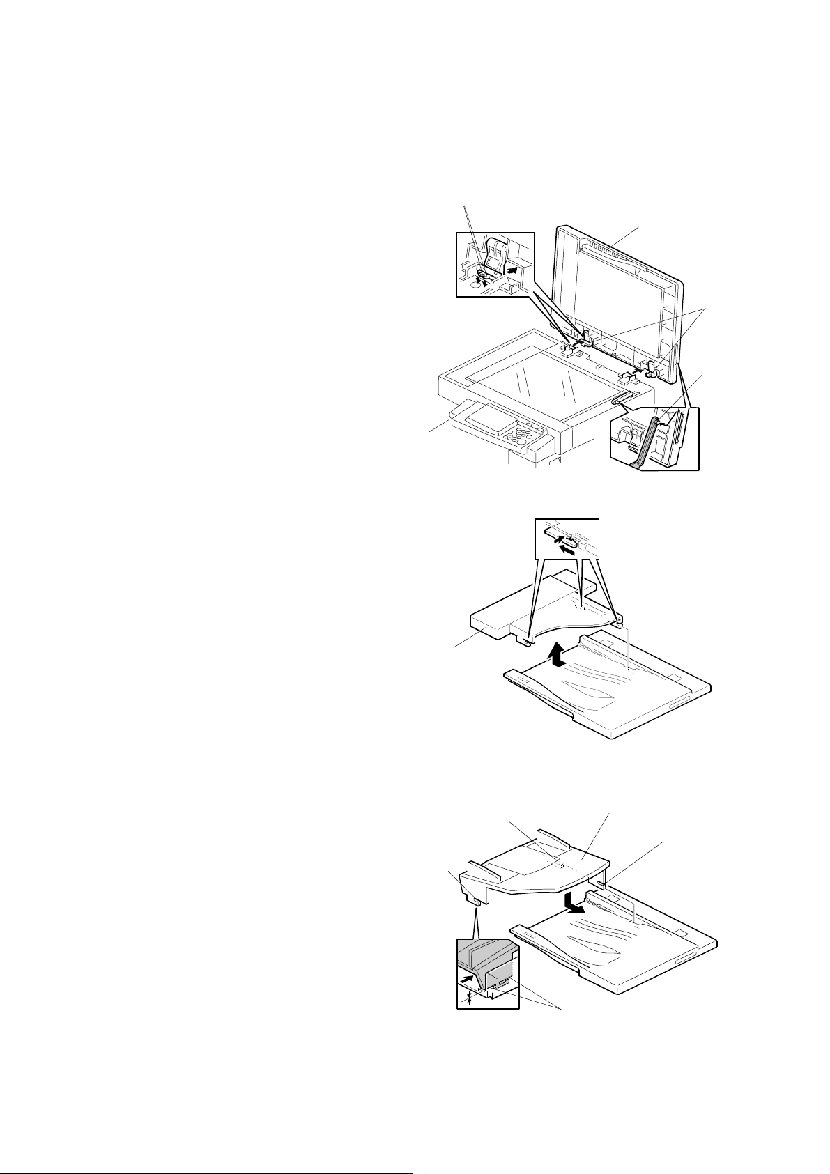
1. Unpack the ADF and remove the packing
tape from the bottom of the ADF body.
[C]
2. Remove the platen cover [A]. To
[A]
remove: Lift the cover, unlatch the
two latches [B] (press down on
the tabs [C] and push the latch
back), and detach the cover from
the hook [D].
[B]
[D]
B046I505.WMF
3. Remove the left piece [E] of the copier's
platen cover by pushing the piece to the
left and then pulling it up and off.
4. Place the DF original table [F] flat onto
the platen cover, so that the 3 latches
go all the way into the openings and so
that the contact area [G] around each
latch is flush against the cover. Then
push so that latch [1] locks into place,
then latch [2], and then latch [3] (at the
rear left).
NOTE: The latches may break if you
try to push the table in at an
angle.
[E]
[1]
[3]
B046I525.WMF
[F]
[2]
[G]
B046I526.WMF
1-18

24 July, 2001 DOCUMENT FEEDER
5. Remove the rear cover [A] (! x 5).
[A]
B046I514.WMF
6. Remove the left scale plate [B] (! x 2).
[B]
Installation
7. Set the DF body [C] onto the copier
in its correct position. Press the latch
[D] to raise the top half of the body,
and fasten to the copier with the 4
hex screws (using the included hex
wrench).
B046I506.WMF
[D]
B046I528.WMF
[C]
1-19
Loading...