


INSTALLATION MANUAL
AVX-7600
This product conforms to new cord colors.
Los colores de los cables de este producto se conforman con un nuevo código de colores.
Dieses Produkt entspricht den neuen Kabelfarben.
Le code de couleur des câbles utilisé pour ce produit est nouveau.
Questo prodotto è conforme ai nuovi codici colori.
De kleuren van de snoeren van dit toestel zijn gewijzigd.
D’INSTALLATION MANUEL |
Nederlands Italiano Français Deutsch Español English |
|
|

Contents |
|
Connecting the Units ................................ |
1 |
Connecting the power cord .............................. |
3 |
When connecting with a Pioneer head unit ...... |
5 |
When connecting with a car stereo |
|
with RCA audio input ................................ |
6 |
When connecting with a DVD player .............. |
7 |
When connecting with a rear view camera ...... |
8 |
Installation ................................................ |
10 |
DIN Front/Rear-mount .................................... |
11 |
DIN Front-mount ............................................ |
11 |
DIN Rear-mount .............................................. |
12 |
Fixing the front panel ...................................... |
12 |
WARNING:
•To avoid the risk of accident and the potential violation of applicable laws, the front DVD or TV feature should never be used while the vehicle is being driven. Also, Rear Displays should not be in a location where it is a visible distraction to the driver.
•In some countries or states the viewing of images on a display inside a vehicle even by persons other than the driver may be illegal. Where such regulations apply, they must be obeyed.
Connecting the Units
CAUTION:
•PIONEER does not recommend that you install or service your display yourself. Installing or servicing the product may expose you to risk of electric shock or other hazards. Refer all installation and servicing of your display to authorized Pioneer service personnel.
•Secure all wiring with cable clamps or electrical tape. Do not allow any bare wiring to remain exposed.
•Do not drill a hole into the engine compartment to connect the yellow lead of the unit to the vehicle battery. Engine vibration may eventually cause the insulation to fail at the point where the wire passes from the passenger compartment into the engine compartment. Take extra care in securing the wire at this point.
•It is extremely dangerous to allow the display lead to become wound around the steering column or gearshift. Be sure to install the display in such a way that it will not obstruct driving.
•Make sure that wires will not interfere with moving parts of the vehicle, such as the gearshift, parking brake or seat sliding mechanism.
•Do not shorten any leads. If you do, the protection circuit may fail to work properly.
1

Note:
•This unit is for vehicles with a 12-volt battery and negative grounding. Before installing it in a recreational vehicle, truck, or bus, check the battery voltage.
•To avoid shorts in the electrical system, be sure to disconnect the ≠ battery cable before beginning installation.
•Refer to the owner’s manual for details on connecting the power amp and other units, then make connections correctly.
•Secure the wiring with cable clamps or adhesive tape. To protect the wiring, wrap adhesive tape around them where they lie against metal parts.
•Route and secure all wiring so it cannot touch any moving parts, such as the gear shift, handbrake and seat rails. Do not route wiring in places that get hot, such as near the heater outlet. If the insulation of the wiring melts or gets torn, there is a danger of the wiring short-circuiting to the vehicle body.
•Don’t pass the yellow lead through a hole into the engine compartment to connect to the battery. This will damage the lead insulation and cause a very dangerous short.
•Do not shorten any leads. If you do, the protection circuit may fail to work when it should.
•Never feed power to other equipment by cutting the insulation of the power supply lead of the unit and tapping into the lead. The current capacity of the lead will be exceeded, causing overheating.
•When replacing fuse, be sure to use only fuse of the rating prescribed on the fuse holder.
•If the RCA pin jack on the unit will not be used, do not remove the caps attached to the end of the connector.
•If this unit is installed in a vehicle that does not have an ACC (accessory) position on the ignition switch, the red lead of the unit should be connected to a terminal coupled with ignition switch ON/OFF operations. If this is not done, the vehicle battery may be drained when you are away from the vehicle for several hours. (Fig. 1)
|
|
CC |
|
|
|
|
|
|
|
|
|
F |
A |
O |
|
|
|
F |
O |
|
|
|
F |
|
N |
|
N |
|||||
O |
|
|
|
|
O |
F |
|
|
|
|
|
|
|
|
S |
|
|
|
S |
||
|
|
|
|
|
|
|
|
|
||
|
|
|
|
|
T |
|
|
|
|
T |
|
|
|
T |
R |
A |
|
|
|
R |
A |
|
|
|
|
|
|
T |
|
|||
ACC position |
No ACC position |
|||||||||
Fig. 1
•Cords for this product and those for other products may be different colors even if they have the same function. When connecting this product to another product, refer to the supplied manuals of both products and connect cords that have the
same function.
English
Español
Italiano Français Deutsch
Nederlands
2

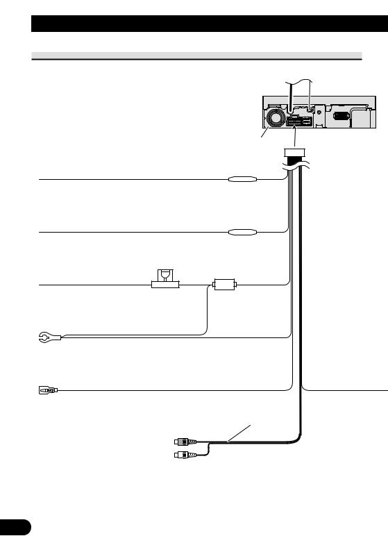
Connecting the Units
Connecting the power cord
Red
To electric terminal controlled by ignition switch (12 V DC) ON/OFF.
Orange/white
To lighting switch terminal.
Yellow |
Fuse holder |
|
To terminal always supplied |
|
|
with power regardless of |
|
|
ignition switch position. |
|
|
|
|
|
|
|
|
Black (ground) |
|
|
To vehicle (metal) body. |
|
|
Violet/white
See the section “When connecting with a rear view camera”
Audio output (AUDIO OUTPUT)
This product
Fuse resistor
Fuse resistor
15 cm
3

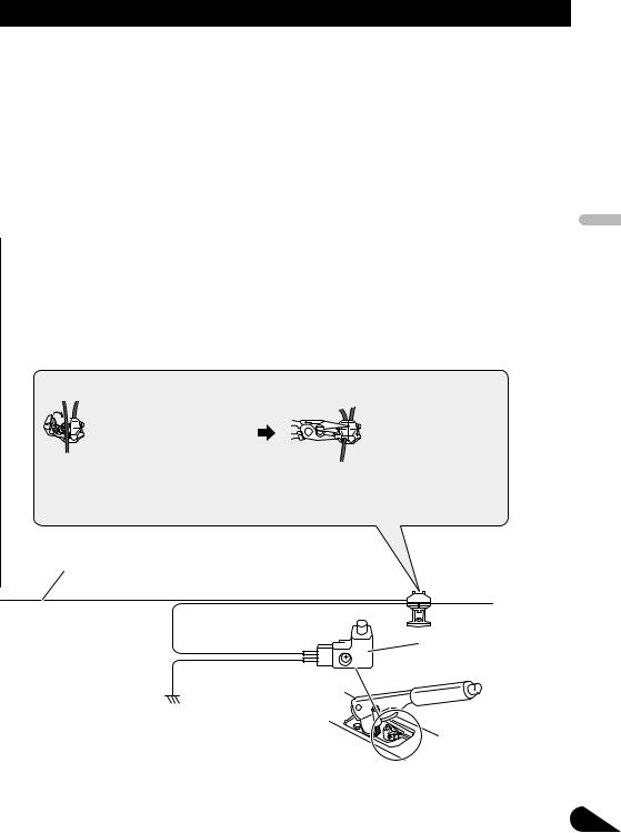
 WARNING
LIGHT GREEN LEAD AT POWER CONNECTOR IS DESIGNED TO DETECT PARKED STATUS AND MUST BE CONNECTED TO THE POWER SUPPLY SIDE OF THE PARKING BRAKE SWITCH. IMPROPER CONNECTION OR USE OF THIS LEAD MAY VIOLATE APPLICABLE LAW AND MAY RESULT IN SERIOUS INJURY OR DAMAGE.
Connection method
1. Clamp the lead. |
2. Clamp firmly with |
|
needle-nosed |
|
pliers. |
Note:
•The position of the parking brake switch depends on the vehicle model. For details, consult the vehicle Owner’s Manual or dealer.
Light green
Used to detect the ON/OFF status of the parking brake.
This lead must be connected to the power supply side of the parking brake switch.
Power supply side
Ground side
Parking brake switch
Fig. 2
English
Español
Italiano Français Deutsch
Nederlands
4

Connecting the Units
When connecting with a Pioneer head unit
AV-BUS input (Blue) |
40 cm |
||||||||||||
|
|
|
|
|
|
|
|
|
|
|
|
|
|
Blue
This product
Head unit
(sold separately)
|
Guide speaker |
|
|
(e.g. CD-TS37GP) |
|
|
(sold separately) |
|
15 cm |
Guide speaker output |
|
(GUIDE SP OUTPUT) |
||
|
If you use this unit with a navigation unit (e.g. AVIC-900DVD), be sure to connect a guide speaker to this unit’s guide speaker output terminal.
Yellow
26 pin cable
Navigation unit (e.g. AVIC-900DVD) (sold separately)
RCA cable (sold separately)
15 cm
Audio output (AUDIO OUTPUT)
Yellow/black
To IP-BUS input (Blue)
Blue
|
Black |
Blue |
IP-BUS cable (supplied |
|
|
with TV tuner) |
Hide-away TV tuner |
|
|
(e.g. GEX-P6400TVP) |
|
|
(sold separately) |
|
RCA to IP-BUS inter connector (e.g. CD-RB10) (sold separately)
AV-BUS cable (supplied |
|
with TV tuner) |
Black |
Fig. 3
5

When connecting with a car stereo with RCA audio input
English
|
|
Guide speaker |
|
|
(e.g. CD-TS37GP) |
|
|
(sold separately) |
|
|
15 cm |
|
|
Guide speaker output |
|
|
(GUIDE SP OUTPUT) |
|
|
If you use this unit with a navigation |
|
|
unit (e.g. AVIC-900DVD), be sure to |
|
|
connect a guide speaker to this unit’s |
|
|
guide speaker output terminal. |
This product |
Yellow |
|
|
|
Navigation unit |
|
|
(e.g. AVIC-900DVD) |
|
|
(sold separately) |
|
|
26 pin cable |
|
|
RCA cable |
|
|
(sold separately) |
15 cm |
|
|
|
Audio output |
|
|
(AUDIO OUTPUT) |
|
When connecting with a car |
|
Car stereo with |
stereo with FM reception |
|
|
capability, use a FM modulator |
RCA input |
|
(e.g. CD-V61FM). |
|
|
Fig. 4
Español
Italiano Français Deutsch
Nederlands
6
Connecting the Units
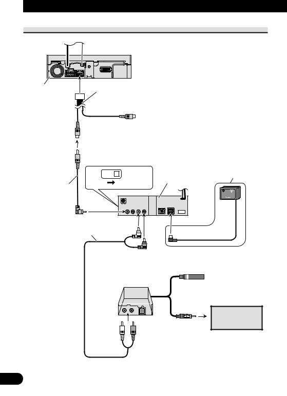
When connecting with a DVD player
This product |
20 cm |
|
Video input 2 |
|
(VIDEO 2/BACK CAMERA INPUT) |
|
Video input 1 |
|
(VIDEO 1 INPUT) |
|
|
DVD player |
Remote sensor (supplied |
IP-BUS |
|
STAND ALONE (e.g. SDV-P7) |
with the DVD player) |
|
|
(sold separately) |
|
RCA cable (supplied with the DVD player)
RCA cable (sold separately)
FM modulator (e.g. CD-V61FM) (sold separately)
Car stereo with FM reception capability
Fig. 5
7

When connecting with a rear view camera
When using this product with a rear view camera, automatic switching to video from a rear view camera when the gear shift is moved to REVERSE (R) position is possible.
WARNING:
•USE INPUT ONLY FOR REVERSE OR MIRROR IMAGE REAR VIEW CAMERA. OTHER USE MAY RESULT IN INJURY OR DAMAGE.
CAUTION:
•The screen image may appear reversed.
•The rear view camera function is to use this product as an aid to keep an eye on trailers, or backing into a tight parking spot. Do not use this function for entertainment purposes.
•The object in rear view may appear closer or more distant than in reality.
English
Español
Italiano Français Deutsch
Nederlands
8
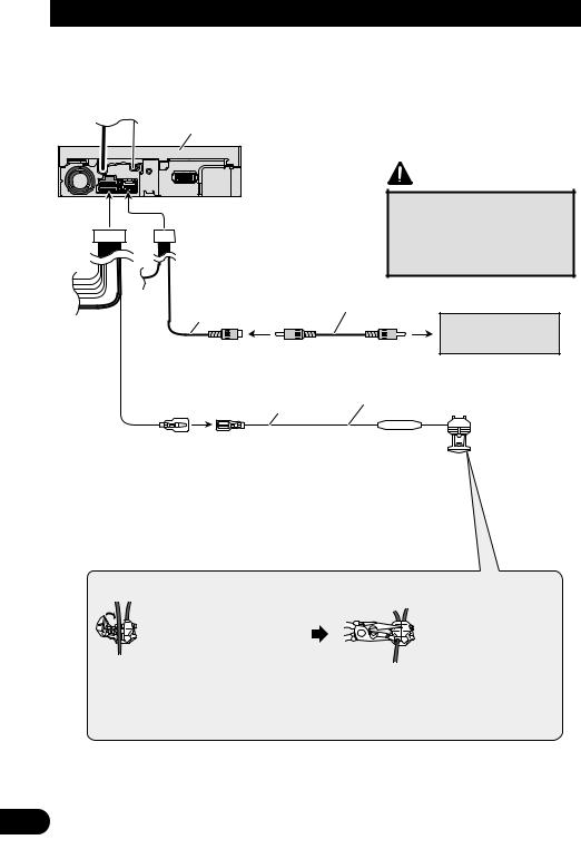
Connecting the Units
This product
|
CAUTION |
|
Pioneer recommends the use of |
|
a camera which outputs mirror |
|
reversed images, otherwise |
|
screen image may appear |
|
reversed. |
|
RCA cable |
20 cm |
(sold separately) |
|
|
|
Rear view camera |
Video input 2 |
To video output |
(VIDEO 2/BACK CAMERA INPUT) |
|
8 m |
Extension lead (supplied) |
|
|
Violet/white |
Fuse resistor |
Of the two lead wires connected to the back |
|
lamp, connect the one in which the voltage |
|
changes when the gear shift is in the REVERSE |
|
(R) position. This connection enables the unit to |
|
sense whether the car is moving forwards or |
|
backwards. |
|
Connection method |
|
1. Clamp the lead. |
2. Clamp firmly with |
|
needle-nosed |
|
pliers. |
Note:
•It is necessary to set to AV INPUT2 in SETUP when connecting a rear view camera.
Fig. 6
9
Installation
Note:
•Before finally installing the unit, connect the wiring temporarily, making sure it is all connected up properly, and the unit and the system work properly.
•Use only the parts included with the unit to ensure proper installation. The use of unauthorized parts can cause malfunctions.
•Consult with your nearest dealer if installation requires the drilling of holes or other modifications of the vehicle.
•Install the unit where it does not get in the driver’s way and cannot injure the passenger if there is a sudden stop, like an emergency stop.
•Do not install the display where it may (i) obstruct the driver’s vision, (ii) impair the performance of any of the vehicle’s operating systems or safety features, including air bags, hazard lamp buttons or (iii) impair the driver’s ability to safely operate the vehicle.
•If installation angle exceeds 30° from horizontal, the unit might not give its optimum performance. (Fig. 7)
30°
Fig. 7
English
Español
Italiano Français Deutsch
Nederlands
10
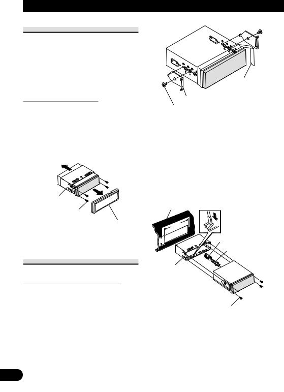
Installation
DIN Front/Rear-mount
This unit can be properly installed either from “Front” (conventional DIN Front-mount) or “Rear” (DIN Rearmount installation, utilizing threaded screw holes at the sides of unit chassis). For details, refer to the following illustrated installation methods.
Before installing the unit
•Remove the frame and the holder. (Fig. 8)
Pull out to remove the frame and then loosen the screws (2 × 3 mm) to remove the holder. (When reattaching the frame, point the side with a groove downwards and attach it.)
Holder
Screw (2 × 3 mm)
Frame
Fig. 8
DIN Front-mount
Installation with the rubber bush
1.Decide the position of the side brackets. (Fig. 9)
When installing in a shallow space, change the position of side brackets. In this case, stick conceal tape on parts that protrude from the dashboard.
Conceal tape
Side bracket
Flush surface screw (5 × 6 mm)
Fig. 9
2.Install the unit into the dashboard. (Fig. 10)
After inserting the holder into the dashboard, then select the appropriate tabs according to the thickness of the dashboard material and bend them. (Install as firmly as possible using the top and bottom tabs. To secure, bend the tabs 90 degrees.)
Dashboard
182
53 |
Rubber bush |
|
|
|
Screw |
Holder
Side bracket 


Screw (2 × 3 mm)
•After installing the unit into the dashboard, reattach the frame.
Fig. 10
11

DIN Rear-mount
Installation using the screw holes on the side of the unit
•Fastening the unit to the factory radio mounting bracket. (Fig. 11) (Fig. 12) (Fig. 13)
Select a position where the screw holes of the bracket and the screw holes of this product become aligned (are fitted), and tighten the screws at 2 places on each side. Use any of binding screws (4 × 3 mm), binding screws (5 × 6 mm) or flush surface screws (5 × 6 mm), depending on the shape of the screw holes in the bracket.
*1 Use binding screws (4 × 3 mm) only.
1 
 1
1
Fig. 11
•When installing in a shallow space, use the following screw holes. In this case, stick conceal tape on parts that protrude from the dashboard.
Conceal tape
1  1
1
Screw
Dashboard or Console
Factory radio mounting bracket
Fig. 13
Fixing the front panel
If you do not operate the removing and attaching the front panel function, use the supplied fixing screws to fix the front panel to this unit.
•Fix the front panel to the unit using fixing screws. (Fig. 14)
Fixing screws
Fig. 14
Fig. 12
English
Español
Italiano Français Deutsch
Nederlands
12

Contenido |
|
Conexión de las unidades ........................ |
1 |
Conexión del cable de alimentación .................. |
3 |
Cuando conecte con una unidad |
|
principal Pioneer ........................................ |
5 |
Cuando conecte con un autoestéreo |
|
con entrada de audio RCA ........................ |
6 |
Cuando conecte con un reproductor |
|
de DVD ...................................................... |
7 |
Cuando conecte con una cámara |
|
de vista trasera ............................................ |
8 |
Instalación ................................................ |
10 |
Montaje trasero/delantero DIN ........................ |
11 |
Montaje delantero DIN .................................... |
11 |
Montaje trasero DIN ........................................ |
12 |
Fijación del panel delantero ............................ |
12 |
ADVERTENCIA:
•Para evitar el riesgo de accidentes e violación potencial de las leyes aplicables, no se debe usar nunca la función de DVD o TV frontal mientras el vehículo esté siendo conducido. Igualmente, los monitores traseros no deben quedarse en un sitio donde puedan causar una distracción visible al conductor.
•En algunos países o estados, puede ser ilícita la visualización de imágenes en un display dentro de un vehículo, incluso por otras personas que no sean el conductor. En los casos en que resulten aplicables, estas normas deben respetarse.
Conexión de las unidades
PRECAUCIÓN:
•PIONEER no recomienda que sea usted mismo quien instale o revise su pantalla. La instalación o revisión del producto puede exponerle a descargas eléctricas u otros peligros. Solicite que todos los trabajos de instalación y revisión de su pantalla los realice el personal de servicio Pioneer autorizado.
•Asegure todo el cableado con abrazaderas de cables o cinta para usos eléctricos. No permita que el cableado pelado permanezca expuesto.
•No taladre un agujero en el compartimiento del motor para conectar el cable amarillo de la unidad a la batería del vehículo. La vibración del motor podría estropear el aislamiento en el punto por donde el cable pasa del compartimiento de los pasajeros al compartimiento del motor. Tenga mucho cuidado para mantener el buen estado del cable en lo relativo a este punto.
•Es peligrosísimo dejar que el cable de la pantalla se enrolle en la base del volante o en la palanca de cambios. Asegúrese de instalar la pantalla de forma que ésta no sea un obstáculo para la conducción.
•Asegúrese de que los cables no interfieran con partes móviles del vehículo tales como la palanca de cambio, el freno de mano o el mecanismo de deslizamiento de los asientos.
•No acorte ningún cable. Si lo hace, el circuito de protección tal vez no funcione correctamente.
1

Nota:
•Esta unidad es para vehículos con batería de 12 voltios y con conexión a tierra. Antes de instalar la unidad en un vehículo recreativo, camioneta, o autobús, revise el voltaje de la batería.
•Para evitar cortocircuitos en el sistema eléctrico, asegúrese de desconectar el cable de la batería ≠ antes de comenzar con la instalación.
•Consulte con el manual del usuario para los detalles sobre la conexión de la alimentación de amperios y de otras unidades, luego haga las conexiones correctamente.
•Asegure el cableado con abrazaderas de cables o con cinta adhesiva. Para proteger el cableado, envuélvalo con cinta adhesiva donde éstos se apoyan sobre las piezas de metal.
•Coloque y asegure todo el cableado de tal manera que no toque las piezas en movimiento, tal como la palanca de cambio de velocidades, el freno de mano, y los pasamanos de los asientos. No coloque el cableado en lugares que se calientan, tal como cerca de la salida de un calefactor. Si el material aislante del cableado se derritiera o se gastara, habrá el peligro de un cortocircuito del cableado a la carrocería del vehículo.
•No pase el conductor amarillo a través de un orificio en el compartimiento del motor para conectar a la batería. Esto dañará el material aislante del conductor y causará un cortocircuito peligroso.
•No acorte ningún conductor. Si lo hiciera, la protección del circuito podría fallar al funcionar cuando debería.
•Nunca alimente energía a otros equipos cortando el aislamiento del conductor de alimentación provista de la unidad y haciendo un empalme con el conductor. La capacidad de corriente del conductor se excederá, causando el recalentamiento.
•Cuando reemplace algún fusible, asegúrese de utilizar solamente un fusible del ratio descrito en el soporte de fusibles.
•Si la toma de clavija RCA en la unidad no se usa, retire las tapas fijadas al extremo del conector.
•Si se instala esta unidad en un vehículo que no tiene una posición ACC (accesorio) en el interruptor de encendido, el conductor rojo de la unidad deberá conectarse al terminal conectado con las operaciones del interruptor de encendido ON/OFF. Si no se hace esto, la batería del vehículo podría drenarse cuando usted esté lejos del vehículo por varias horas. (Fig. 1)
|
|
CC |
|
|
|
|
|
|
|
|
|
F |
A |
O |
|
|
|
F |
O |
|
|
|
F |
|
N |
|
N |
|||||
O |
|
|
|
|
O |
F |
|
|
|
|
|
|
|
|
S |
|
|
|
S |
||
|
|
|
|
|
|
|
|
|
||
|
|
|
|
|
T |
|
|
|
|
T |
|
|
|
T |
R |
A |
|
|
|
R |
A |
|
|
|
|
|
|
T |
|
|||
Posición ACC |
No en la posición ACC |
|||||||||
Fig. 1
•Los cables para este producto y aquéllas para otros productos pueden ser de colores diferentes aun si tienen la misma función. Cuando se conecta este producto a otro, refiérase a los manuales de ambos productos y conecte los
cables que tienen la misma función.
English
Español
Italiano Français Deutsch
Nederlands
2
Conexión de las unidades
Conexión del cable de alimentación
Rojo
Al terminal de energía eléctrica controlado por el interruptor de encendido del vehículo (12 V de CC.) ON/OFF.
Anaranjado/blanco
Al terminal de interruptor de iluminación.
Amarillo |
Portafusible |
||
Al terminal con suministro |
|||
|
|||
constante de electricidad, |
|
||
independientemente de la posición |
|
||
del interruptor de encendido. |
|
||
|
|
||
|
|
|
|
Negro (masa) |
|
||
A la carrocería del veículo |
|
||
(parte metálica). |
|
||
Violeta/blanco
Vea la sección “Cuando conecte con una cámara de vista trasera”
Salida de audio (AUDIO OUTPUT)
Este producto
Resistencia de fusible
Resistencia de fusible
15 cm
3
 ADVERTENCIA
EL CABLE VERDE CLARO DEL CONECTOR DE ALIMENTACIÓN ESTÁ
DISEÑADO PARA DETECTAR SI EL VEHÍCULO ESTÁ ESTACIONADO
Y DEBE CONECTARSE CON EL LADO DE LA FUENTE DE
ALIMENTACIÓN DEL INTERRUPTOR DEL FRENO DE MANO. LA
CONEXIÓN O EL USO INCORRECTO DE ESTE CABLE PUEDE
INFRINGIR LAS LEYES PERTINENTES Y OCASIONAR LESIONES
FÍSICAS O DAÑOS GRAVES.
Método de conexión
1. Apriete el cable. |
2. Apriete firmemente |
con alicates de punta de aguja.
Nota:
•La posición del freno de estacionamiento depende
del modelo del vehículo. Para conocer detalles, consulte
el manual del propietario del vehículo o a su concesionario.
Lado de alimentación |
Interruptor del |
|
freno de mano |
Lado de masa
Fig. 2
English
Español
Italiano Français Deutsch
Nederlands
4

Conexión de las unidades
Cuando conecte con una unidad principal Pioneer
Entrada AV-BUS (Azul) |
40 cm |
||||||||||||
|
|
|
|
|
|
|
|
|
|
|
|
|
|
Azul
Este producto
Unidad principal (vendida separadamente)
Altavoz de guía (ej. CD-TS37GP)
(vendido separadamente)
15 cm |
Salida de altavoz de guía |
|
(GUIDE SP OUTPUT) |
||
|
Si utiliza esta unidad con una unidad de navegación (por ejemplo, AVIC900DVD), asegúrese de conectar un altavoz de guía a este terminal de salida de altavoz de guía de la unidad.
Amarillo
Cable de 26 clavijas Unidad de navegación
(AVIC-900DVD, por exemplo)
(vendido separadamente)
Cable RCA (vendido separadamente)
15 cm
Salida de audio (AUDIO OUTPUT)
Amarillo/negro
A la entrada IP-BUS (Azul)
Azul
|
Negro |
Azul |
Cable IP-BUS (suministrado |
|
|
con el sintonizador de TV) |
Sintonizador TV oculto- |
|
|
||
|
lejos (GEX-P6400 TVP, |
|
|
por exemplo) (vendido |
|
|
separadamente) |
|
RCA a interconector IP-BUS (por ejemplo, CD-RB10) (vendido separadamente)
Cable AV-BUS (suministrado |
Negro |
con el sintonizador de TV) |
Fig. 3
5

Cuando conecte con un autoestéreo con entrada de audio RCA
English
|
Altavoz de guía |
|
(ej. CD-TS37GP) |
|
(vendido separadamente) |
|
15 cm |
|
Salida de altavoz de guía |
|
(GUIDE SP OUTPUT) |
|
Si utiliza esta unidad con una unidad de |
|
navegación (por ejemplo, AVIC- |
|
900DVD), asegúrese de conectar un |
|
altavoz de guía a este terminal de salida |
|
de altavoz de guía de la unidad. |
Este producto |
Amarillo |
|
Unidad de navegación |
|
(AVIC-900DVD, por |
|
exemplo) |
|
(vendido separadamente) |
|
Cable de 26 clavijas |
|
Cable RCA |
|
(vendido separadamente) |
|
15 cm |
|
|
|
|
|
|
Salida de audio |
|||||
(AUDIO OUTPUT) |
|||||
Cuando conecte con un |
|
|
|
|
|
|
|
|
|
|
|
autoestéreo con capacidad de |
Autoestéreo con |
||||
recepción FM, utilice un |
entrada RCA |
||||
modulador FM (por ejemplo, |
|
|
|
|
|
CD-V61FM). |
|
|
|
|
|
Fig. 4
Español
Italiano Français Deutsch
Nederlands
6

Conexión de las unidades
Cuando conecte con un reproductor de DVD
Este producto |
20 cm |
|
|
|
Entrada de vídeo 2 |
|
|
|
(VIDEO 2/BACK CAMERA INPUT) |
|
|
|
Entrada de vídeo 1 |
|
|
|
(VIDEO 1 INPUT) |
|
|
|
|
Reproductor de |
Sensor remoto |
|
|
DVD (por ejemplo, |
(suministrado con |
|
IP-BUS |
STAND ALONE SDV-P7) (vendido |
reproductor de DVD) |
Cable RCA |
|
separadamente) |
|
|
|
|
|
(suministrado con |
|
|
|
el reproductor de |
|
|
|
DVD) |
|
|
|
Cable RCA  (vendido separadamente)
Modulador FM (por ejemplo, CD-V61FM) (vendido separadamente)
Autoestéreo con capacidad de recepción FM
Fig. 5
7
Cuando conecte con una cámara de vista trasera
Cuando utilice este producto con una cámara de vista trasera, se puede realizar la conmutación automática a vídeo desde una cámara de vista trasera cuando se desplaza la palanca de cambio de marchas a REVERSE (R).
ADVERTENCIA:
•UTILICE SOLAMENTE PARA CÁMARA DE VISTA TRASERA DE IMAGEN INVERTIDA O DE ESPEJO. CUALQUIER OTRO USO PUEDE CAUSAR LESIONES O DAÑOS.
English
PRECAUCIÓN:
•La imagen de la pantalla puede aparecer invertida.
•La función de cámara de vista trasera es para utilizar de este producto como una ayuda para mantener un ojo en remolques, o al estacionar de marcha atrás en un estacionamiento estrecho. No utilice esta función para propósitos de entretenimiento.
•El objeto en la vista trasera puede parecer más próximo o más distante que en la realidad.
Español
Italiano Français Deutsch
Nederlands
8

Conexión de las unidades
Este producto
|
PRECAUCIÓN |
|
|
Pioneer recomienda el uso de una |
|
|
cámara que genere imágenes |
|
|
invertidas de espejo; de lo |
|
|
contrario, puede que la imagen en |
|
|
la pantalla aparezca invertida. |
|
|
Cable RCA |
|
20 cm |
(vendido separadamente) |
|
Cámara de |
||
|
||
|
vista trasera |
|
Entrada de vídeo 2 |
A la salida de vídeo |
|
(VIDEO 2/BACK CAMERA INPUT) |
|
|
8 m |
Cable de extensión (suministrado) |
|
|
||
Violeta/blanco |
Resistencia |
|
De los dos conductores conectados a la lámpara |
de fusible |
|
trasera, conecte el conductor cuyo voltaje cambia |
|
|
cuando se desplaza la palanca de cambio de marcha |
|
|
a la posición REVERSE (R). Esta conexión permite |
|
|
que la unidad detecte si el vehículo está se |
|
|
moviendo hacia delante o hacia atrás. |
|
|
Método de conexión |
|
|
1. Apriete el cable. |
2. Apriete firmemente |
|
|
con alicates de |
|
|
punta de aguja. |
Nota:
•Se requiere ajustar a AV INPUT2 en SETUP cuando se conecta la cámara de vista trasera.
Fig. 6
9

Instalación
Nota:
•Antes de finalmente instalar la unidad, conecte el cableado temporalmente y asegúrese de que todo esté conectado correctamente y que la unidad y el sistema funcionan debidamente.
•Utilice sólo las piezas que se incluyen con esta unidad para asegurar la instalación adecuada. El uso de piezas no autorizadas podría causar fallos de funcionamiento.
•Consulte con su distribuidor si la instalación requiere del taladro de orificios u otras modificaciones del vehículo.
•Instale la unidad donde no alcance el espacio del conductor, y donde no pueda dañar a los pasajeros si sucediera un paro repentino, como una detención de emergencia.
•No instale el display en un lugar que (i) pueda obstaculizar la visión del conductor, (ii) pueda alterar el funcionamiento de los sistemas operativos o los dispositivos de seguridad del vehículo, en particular las bolsas de aire y los botones de luces de seguridad o (iii) pueda afectar la capacidad del conductor para manejar el vehículo de manera segura.
•Si el ángulo de la instalación excede los 30° del lado horizontal, la unidad podría no brindar su óptimo funcionamiento. (Fig. 7)
30°
Fig. 7
English
Español
Italiano Français Deutsch
Nederlands
10
 Loading...