


ORDER NO.
RRV4456
BDP-160-K
BDPlu-ray 3DTM PLAYER -160-K
BDP-160-S
BDP-160
THIS MANUAL IS APPLICABLE TO THE FOLLOWING MODEL(S) AND TYPE(S).
Model |
Type |
Power Requirement |
DVD |
BD |
Serial No. |
Remarks |
|
Region No. |
Region No. |
||||||
|
|
|
|
|
|||
|
|
|
|
|
|
|
|
BDP-160-K |
YXE8 |
AC 110 V to 240 V |
2 |
B |
&&&#####YY |
YY : Europe |
|
|
|
|
|
|
|
|
|
BDP-160-K |
VXE8 |
AC 110 V to 240 V |
2 |
B |
&&&#####GB |
GB : U.K |
|
|
|
|
|
|
|
|
|
BDP-160-S |
YXE8 |
AC 110 V to 240 V |
2 |
B |
&&&#####YY |
YY : Europe |
|
|
|
|
|
|
|
|
|
BDP-160 |
FXE |
AC 110 V to 240 V |
3 |
A |
&&&#####TA |
TA : Taiwan |
|
|
|
|
|
|
|
|
|
BDP-160 |
LXE |
AC 110 V to 240 V |
3 |
A |
&&&#####LL |
LL : Asean |
|
|
|
|
|
|
|
|
|
BDP-160 |
PWXE |
AC 110 V to 240 V |
4 |
B |
&&&#####PP |
PP : Oceania |
|
|
|
|
|
|
|
|
|
BDP-160 |
SXE |
AC 110 V to 240 V |
5 |
C |
&&&#####UR |
UR : Russia |
|
|
|
|
|
|
|
|
|
BDP-160 |
AXQ5 |
AC 110 V to 240 V |
6 |
C |
&&&#####CN |
CN : China |
|
|
|
|
|
|
|
|
PIONEER CORPORATION 1-1, Shin-ogura, Saiwai-ku, Kawasaki-shi, Kanagawa 212-0031, Japan
PIONEER ELECTRONICS (USA) INC. P.O. Box 1760, Long Beach, CA 90801-1760, U.S.A.
PIONEER EUROPE NV Haven 1087, Keetberglaan 1, 9120 Melsele, Belgium
PIONEER ELECTRONICS ASIACENTRE PTE. LTD. 253 Alexandra Road, #04-01, Singapore 159936
 PIONEER CORPORATION 2013
K-ZZZ JULY 2013 Printed in Japan
|
1 |
|
2 |
|
3 |
|
4 |
|
|
|
|
|
|
SAFETY INFORMATION
A
This service manual is intended for qualified service technicians; it is not meant for the casual do-it- yourselfer. Qualified technicians have the necessary test equipment and tools, and have been trained to properly and safely repair complex products such as those covered by this manual.
Improperly performed repairs can adversely affect the safety and reliability of the product and may void the warranty. If you are not qualified to perform the repair of this product properly and safely, you should not risk trying to do so and refer the repair to a qualified service technician.
B |
|
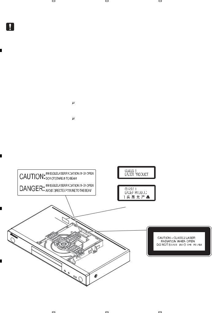
Laser Pickup specifications and Laser characteristics |
|
|||
|
|
|||||
|
|
BD |
Wave length : 405 nm |
|
|
|
|
|
|
|
Operating output : 1.16 mW CW, Class 1 |
||
|
|
|
|
Maximum output : Class 2 (under fault condition) |
||
|
|
DVD |
Wave length : 658 nm |
|
|
|
|
|
|
|
Operating output : 178 |
W CW, Class 1 |
|
|
|
|
|
|||
|
|
|
|
Maximum output : Class 1 (under fault condition) |
||
|
|
CD |
Wave length : 790 nm |
|
|
|
|
|
|
|
Operating output : 174 |
W CW, Class 1 |
|
|
|
|
|
Maximum output : Class 1 (under fault condition) |
||
C |
|
|
|
|
|
|
|
|
|
|
|
|
|
LABEL CHECK
The following caution appears on your unit. Location: inside of the unit
D
E
BDP-160/YXE8, /VXE8, /SXE, /PWXE, /LXE
BDP-160/AXQ5
(Printed on the Rear Panel)
The following caution label appears on your unit.
Location: inside of the unit
F
2 |
BDP-160-K |
|
1 |
|
2 |
|
3 |
|
4 |
|
|
|
|
|
|

|
5 |
|
|
6 |
|
|
7 |
|
|
8 |
|
|
|
|
|||||||
CONTENTS |
|
|
|
|
|
|
|
|||
|
SAFETY INFORMATION ......................................................................................................................................................... |
|
|
|
|
|
|
2 |
||
|
1. SERVICE PRECAUTIONS.................................................................................................................................................... |
|
|
|
|
|
|
4 |
||
|
1.1 NOTES ON SOLDERING............................................................................................................................................... |
|
|
|
|
|
|
4 |
||
|
2. SPECIFICATIONS................................................................................................................................................................. |
|
|
|
|
|
|
5 |
||
|
2.1 ACCESSORIES.............................................................................................................................................................. |
|
|
|
|
|
|
5 |
||
|
2.2 SPECIFICATIONS .......................................................................................................................................................... |
|
|
|
|
|
|
5 |
||
|
3. BASIC ITEMS FOR SERVICE .............................................................................................................................................. |
|
|
|
|
|
|
6 |
||
|
3.1 CHECK POINTS AFTER SERVICING |
........................................................................................................................... |
|
|
|
|
|
6 |
||
|
3.2 PCB LOCATIONS........................................................................................................................................................... |
|
|
|
|
|
|
7 |
||
|
3.3 JIGS LIST ....................................................................................................................................................................... |
|
|
|
|
|
|
7 |
||
|
4. BLOCK DIAGRAM ................................................................................................................................................................ |
|
|
|
|
|
|
8 |
||
|
4.1 OVERALL CONNECTION DIAGRAM ............................................................................................................................ |
|
|
|
|
|
|
8 |
||
|
4.2 BLOCK DIAGRAM........................................................................................................................................................ |
|
|
|
|
|
|
10 |
||
|
4.3 POWER BLOCK DIAGRAM ......................................................................................................................................... |
|
|
|
|
|
|
12 |
||
|
5. DIAGNOSIS ........................................................................................................................................................................ |
|
|
|
|
|
|
14 |
||
|
5.1 DIAGNOSIS FLOWCHART .......................................................................................................................................... |
|
|
|
|
|
|
14 |
||
|
5.2 CONFIMATION OF THE Wi-Fi MODULE..................................................................................................................... |
|
|
|
19 |
|||||
|
6. SERVICE MODE................................................................................................................................................................. |
|
|
|
|
|
|
20 |
||
|
6.1 HOW TO ENTER TO SERVICE MODE ....................................................................................................................... |
|
|
|
20 |
|||||
|
6.2 DESCRIPTION OF EACH ITEM................................................................................................................................... |
|
|
|
|
|
|
20 |
||
|
6.3 DETAILED DESCRIPTION OF ITEMS USED IN SERVICE......................................................................................... |
|
|
|
21 |
|||||
|
7. DISASSEMBLY ................................................................................................................................................................... |
|
|
|
|
|
|
24 |
||
|
8. EACH SETTING AND ADJUSTMENT ................................................................................................................................ |
|
|
|
|
|
|
32 |
||
|
8.1 NECESSARY ADJUSTMENT POINTS ........................................................................................................................ |
|
|
|
32 |
|||||
|
8.2 FIRMWARE UPDATE ................................................................................................................................................... |
|
|
|
|
|
|
33 |
||
|
8.3 METHOD OF READING OUT BARCODE DATA BY SERVICE MODE ....................................................................... |
|
|
|
33 |
|||||
|
8.4 METHOD OF WRITING BARCODE DATA BY USING REMOTE CONTROL UNIT .................................................... |
34 |
||||||||
|
8.5 METHOD OF READING OUT AND WRITING BARCODE DATA BY USING PC AND SERVICE JIG |
........................ 36 |
||||||||
|
9. EXPLODED VIEWS AND PARTS LIST .............................................................................................................................. |
|
|
|
|
|
|
40 |
||
|
9.1 PACKING SECTION..................................................................................................................................................... |
|
|
|
|
|
|
40 |
||
|
9.2 EXTERIOR SECTION .................................................................................................................................................. |
|
|
|
|
|
|
42 |
||
|
10. SCHEMATIC DIAGRAM.................................................................................................................................................... |
|
|
|
|
|
|
43 |
||
|
11. PCB CONNECTION DIAGRAM ........................................................................................................................................ |
|
|
|
|
|
|
44 |
||
|
11.1 MAIN BOARD ASSY................................................................................................................................................... |
|
|
|
|
|
|
44 |
||
|
11.2 FRONT BOARD and SWITCH BOARD ASSYS......................................................................................................... |
|
|
|
48 |
|||||
|
11.3 POWER BOARD ASSY .............................................................................................................................................. |
|
|
|
|
|
|
50 |
||
|
12. PCB PARTS LIST.............................................................................................................................................................. |
|
|
|
|
|
|
52 |
||
A
B
C
D
E
F
BDP-160-K |
3 |
|
5 |
|
6 |
|
7 |
|
8 |
|
|
|
|
|
|

|
1 |
|
2 |
|
3 |
|
4 |
|
|
|
|
|
|
1. SERVICE PRECAUTIONS
1.1 NOTES ON SOLDERING
A • For environmental protection, lead-free solder is used on the printed circuit boards mounted in this unit.
Be sure to use lead-free solder and a soldering iron that can meet specifications for use with lead-free solders for repairs accompanied by reworking of soldering.
•Compared with conventional eutectic solders, lead-free solders have higher melting points, by approximately 40 ºC. Therefore, for lead-free soldering, the tip temperature of a soldering iron must be set to around 373 ºC in general, although
the temperature depends on the heat capacity of the PC board on which reworking is required and the weight of the tip of the soldering iron.
Do NOT use a soldering iron whose tip temperature cannot be controlled.
Compared with eutectic solders, lead-free solders have higher bond strengths but slower wetting times and higher melting
Btemperatures (hard to melt/easy to harden).
The following lead-free solders are available as service parts:
•Parts numbers of lead-free solder: GYP1006 1.0 in dia.
GYP1007 0.6 in dia. GYP1008 0.3 in dia.
C
D
E
F
4 |
BDP-160-K |
|
1 |
|
2 |
|
3 |
|
4 |
|
|
|
|
|
|

|
5 |
|
6 |
|
7 |
|
8 |
|
|
|
|
2. SPECIFICATIONS
2.1 ACCESSORIES
• Remote control x 1 (YXE8, VXE8, FXE, LXE, PWXE, SXE : 06-T2446E-A005) (RC-2426) (AXQ5 : 06-T2446E-A006) (RC-2428)
• AAA/R03 dry cell batteries x 2
• Power cord (YXE8, LXE, SXE : 51-DC0120-0CRA3) (VXE8 : 51-DC0120-0CRD4)
(FXE : 51-NC0150-0LNA9)
(PWXE : 51-JC0120-0PNC7)
(AXQ5 : 51-GC0120-0CRA5)
•Warranty card (European models only)
•Software license notice (YXE8, VXE8, FXE, LXE, PWXE, SXE : ARC8260)
(AXQ5 : ARC8261)
• Operating instructions (YXE8 : 72-BDP160-EURB1)
(YXE8, VXE8, LXE, PWXE : 72-BDP160-GBRB1) (FXE : 72-BDP160-TWNB1)
(LXE : 72-BDP160-TWNB1)
(SXE : 72-BDP160-RUSB1)
(AXQ5 : 72-BDP160-CHNB1)
2.2 SPECIFICATIONS
Model |
|
BDP-160 |
|
|
|
|
BDP-160-K |
|
|
|
BDP-160-S |
|
|
|
|
Type |
|
Blu-ray 3DTM PLAYER |
|
Rated voltage |
|
AC 110 V to 240 V |
|
|
|
|
|
Rated frequency |
|
50 Hz/60 Hz |
|
|
|
|
|
Power consumption |
|
17 W |
|
|
|
||
Power consumption (standby) |
0.3 W |
||
|
|
||
Power consumption (quick start) |
7 W |
||
|
|
|
|
Weight |
|
2.0 kg |
|
|
|
||
External dimensions (including projecting parts) |
435 mm (W) x 58 mm (H) x 250 mm (D) |
||
|
|
||
Tolerable operating temperature |
+5 °C to +35 °C |
||
|
|
||
Tolerable operating humidity |
5 % to 85 % (no condensation) |
||
|
|
|
|
Output |
HDMI |
|
1 set, 19-pin: 5 V, 250 mA |
|
|
||
|
|
|
|
|
Audio outputs |
2-channel (left/right) |
1 set, RCA jacks |
|
|
|
|
terminals |
|
Audio output level |
200 mVrms (1 kHz, –20 dB) |
Digital audio outputs |
|
|
|
Coaxial |
1 set, RCA jacks |
||
|
|
Frequency response |
4 Hz to 88 kHz (192 kHz sampling) |
|
|
|
|
LAN |
|
1 set, Ethernet jack (10BASE-T/100BASE-TX) |
|
|
|
||
Wireless LAN (internal antenna) |
Integrated IEEE 802.11n (2.4 GHz band) wireless |
||
|
|
|
networking access, compatible with 802.11b/g Wi-Fi |
|
|
|
networks |
|
|
|
|
USB |
|
2 set, Type A |
|
|
|
|
|
A
B
C
D
E
 Note
Note
•The specifications and design of this product are subject to change without notice.
•This item incorporates copy protection technology that is protected by U.S. patents and other intellectual property rights of Rovi Corporation. Reverse engineering and disassembly are prohibited.
Do not connect the unit through a VCR. Video signals fed through VCRs may be affected by copyright protection
F
systems and the picture will be distorted on the television.
•Corporation and product names mentioned herein are trademarks or registered trademarks of the respective corporations.
BDP-160-K |
5 |
|
5 |
|
6 |
|
7 |
|
8 |
|
|
|
|
|
|

|
|
|
|
1 |
|
|
2 |
|
|
3 |
|
|
4 |
|
|
|
|
|
|
|
|
|
|||||||
|
|
3. BASIC ITEMS FOR SERVICE |
|
|
|
|
|
|||||||
|
|
3.1 CHECK POINTS AFTER SERVICING |
|
|
|
|
|
|||||||
A |
|
To keep the product quality after servicing, confirm recommended check points shown below. |
|
|
||||||||||
|
|
|
|
|
||||||||||
|
|
|
|
|
|
|
|
|
|
|
|
|
||
|
|
|
No. |
|
|
Procedures |
|
|
|
Check points |
|
|
||
|
|
|
|
|
|
|
|
|||||||
|
|
|
1 |
Confirm the firmware version on Test Mode. |
The version of the firmware must be latest. |
|
|
|||||||
|
|
|
|
|
|
|
|
|
Update firmware to the latest one, if it is not the latest. |
|
||||
|
|
|
|
|
|
|
|
|
|
|
||||
|
|
|
|
|
|
|
||||||||
|
|
|
2 |
Confirm whether the customer complain has been solved. |
The customer complain must not be reappeared. |
|
||||||||
|
|
|
|
|||||||||||
|
|
|
If the customer complain occurs with the specific disc, use it for |
Video, audio and operations must be normal. |
|
|
||||||||
|
|
|
|
the operation check. |
|
|
|
|
|
|
|
|
||
|
|
|
|
|
|
|
|
|
|
|
||||
|
|
|
3 |
Play back a CD. |
|
|
|
Audio and operations must be normal. |
|
|
||||
|
|
|
(track search) |
|
|
|
|
|
|
|
|
|||
|
|
|
|
|
|
|
|
|
|
|
|
|||
B |
|
|
|
|
|
|
|
|
|
|
|
|
|
|
|
4 |
Play back a DVD. |
|
|
|
Video, audio and operations must be normal. |
|
|
||||||
|
|
|
|
|
|
|
|
|||||||
|
|
|
(Menu operation, Title/chapter search) |
|
|
|
|
|
|
|
|
|||
|
|
|
|
|
|
|
|
|
|
|
|
|||
|
|
|
|
|
|
|
|
|
|
|
||||
|
|
|
5 |
Play back a BD. |
|
|
|
Video, audio and operations must be normal. |
|
|
||||
|
|
|
(Menu operation, Title/chapter search) |
|
|
|
|
|
|
|
|
|||
|
|
|
|
|
|
|
|
|
|
|
|
|||
|
|
|
|
|
|
|
|
|
|
|||||
|
|
|
6 |
Check the appearance of the product. |
|
|
|
No scratches or dirt on its appearance after receiving it for |
|
|||||
|
|
|
|
|
|
|
|
|
service. |
|
|
|||
|
|
|
|
|
|
|
|
|
|
|
|
|||
|
|
|
|
|
|
|
|
|
|
|
|
|
|
|
See the table below for the items to be checked regarding video and audio.
C |
Item to be checked regarding video |
Item to be checked regarding audio |
|
|
|
||
|
|
Block noise |
Distortion |
|
|
|
|
|
|
Horizontal noise |
Noise |
|
|
|
|
|
|
Dot noise |
Volume too low |
|
|
|
|
|
|
Disturbed image (video jumpiness) |
Volume too high |
|
|
|
|
|
|
Too dark |
Volume fluctuating |
|
|||
|
|
|
|
|
|
Too bright |
Sound interrupted |
|
|
|
|
|
|
Color disappearance |
|
|
|
|
|
|
|
Mottled color |
|
|
|
|
|
D |
|
||
|
|
Cleaning |
|
Be sure to clean the following positions by using the prescribed cleaning tools shown below as occasion demands.
|
|
Position to be cleaned |
Name |
Part No. |
Remarks |
|
|
||||
|
|||||
|
|
|
|
|
|
|
|
Pickup leneses |
Cleaning liquid |
GEM1004 |
Refer to “7. DISASSEMBLY”. |
|
|
|
|
|
|
|
|
|
Cleaning paper |
GED-008 |
|
|
|
|
|
|
|
E
F
6 |
BDP-160-K |
|
1 |
|
2 |
|
3 |
|
4 |
|
|
|
|
|
|
|
5 |
|
6 |
|
7 |
|
8 |
|
|
|
|
|
|
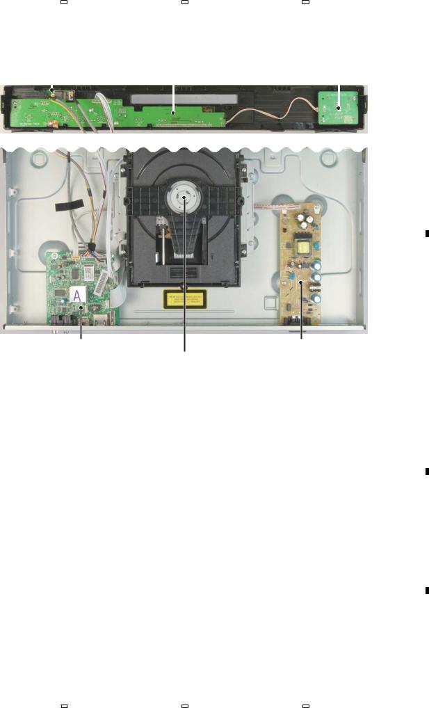
3.2 PCB LOCATIONS
A
WIFI MODULE ASSY |
FRONT CONTROL BOARD ASSY |
SWITCH BOARD ASSY |
|
|||||||
|
|
|
B |
|
|
C |
|
|
||
|
|
|
|
|
||||||
|
|
|
|
|
|
|
|
|
|
|
|
|
|
|
|
|
|
|
|
|
|
|
|
|
|
|
|
|
|
|
|
|
|
|
|
|
|
|
|
|
|
|
|
B
C
|
A |
|
|
|
D |
|
|
MAIN BOARD ASSY |
Loader ASSY |
POWER BOARD ASSY |
|
||||
|
|||||||
NOTES: - Parts marked by “NSP” are generally unavailable because they are not in our Master Spare Parts List.
-The > mark found on some component parts indicates the importance of the safety factor of the part. Therefore, when replacing, be sure to use parts of identical designation.
Mark No. Description |
|
Part No. |
Mark |
No. Description |
|
Part No. |
|
|
|
|
|||||
|
|
|
|
|
|
|
|
LIST OF ASSEMBLIES |
|
|
|
1..FRONT BOARD ASSY |
08-BDP160-FV0 |
||
|
1..MAIN BOARD ASSY |
08-BDP160-MA0/Y |
|
||||
|
|
|
|
|
|||
|
(YXE8, VXE8, PWXE, SXE) |
|
|
|
1..SWITCH BOARD ASSY |
08-BDP160-SB0 |
|
|
1..MAIN BOARD ASSY(FXE) |
08-BDP160-MA2/F |
|
||||
|
|
|
|
|
|||
|
1..MAIN BOARD ASSY(LXE) |
08-BDP160-MA2/L |
> 1..POWER BOARD ASSY |
08-P015BE-PW0 |
|||
|
1..MAIN BOARD ASSY(AXQ5) |
08-BDP160-MA1/A |
|||||
|
|
|
|
|
|||
3.3 JIGS LIST
Name |
Jig No. |
Remarks |
|
DVD Test Disc (DVD-Video) |
GGV1025 |
Check of DVD-Video |
|
|
|
|
|
BD-ROM Test Disc |
GGV1350 |
Check of BD-ROM |
|
|
|
|
|
BD-ROM Test Disc (One layer type) |
GGV1368 |
For Adjustment |
|
|
|
|
|
Service Jig |
GGF1676 |
Refer to “ 8.6 METHOD OF READING OUT AND |
|
WRITING BARCODE DATA BY USING PC AND |
|||
(Including a USB cable) |
|||
|
SERVICE JIG ” |
||
|
|
||
|
|
|
D
E
F
BDP-160-K |
7 |
|
5 |
|
6 |
|
7 |
|
8 |
|
|
|
|
|
|

|
1 |
|
2 |
|
3 |
|
4 |
|
|
|
|
|
|
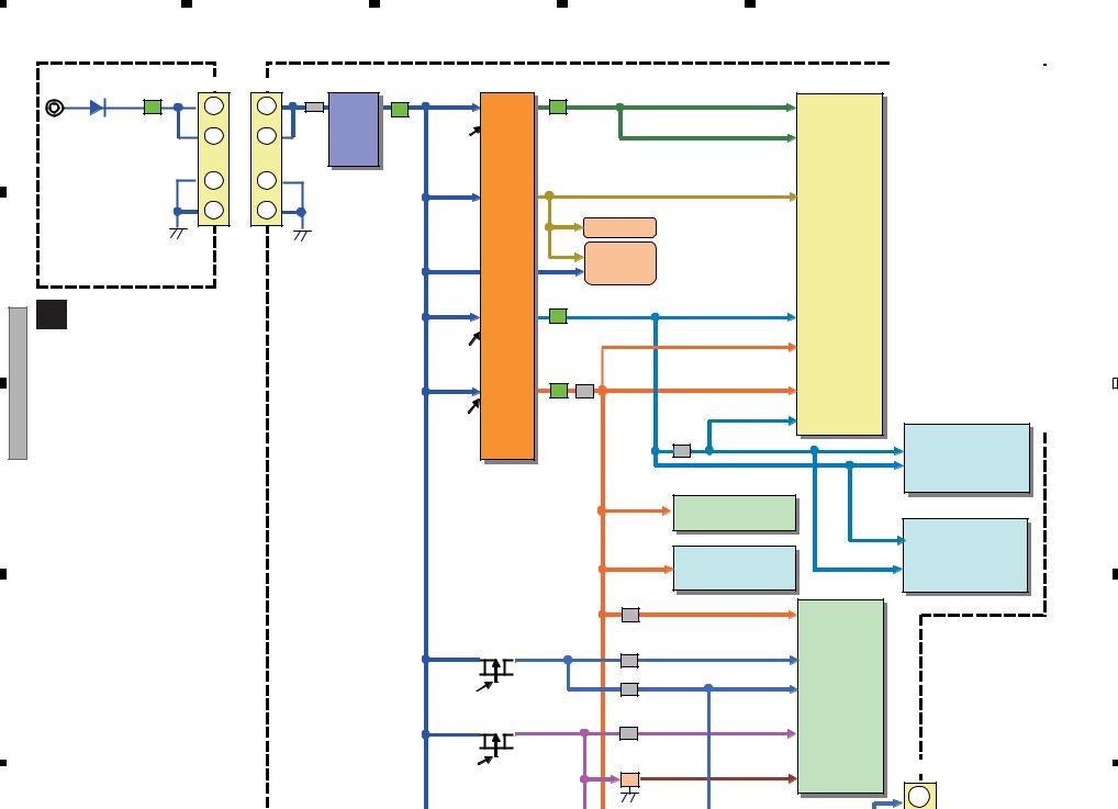
4. BLOCK DIAGRAM
4.1 OVERALL CONNECTION DIAGRAM
A |
|
|
|
|
|
|
|
|
|
|
|
|
|
|
|
|
|
|
|
P1 (Ethernet ) |
P5 (HDMI) |
|
|
|
|
|
|
P2 (USB_2) |
|
|
|
|
|
|
||||
B |
|
|
|
|
|
|
|
|
|
|
|
|
A MAIN BOARD ASSY |
|
|
|
|
|
|
|
|
|
|
|
|
(YXE8, VXE8, PWXE, SXE :08-BDP160-MA0/Y) |
|
|
|
|
|
|
||||||
(FXE :08-BDP160-MA2/F) |
|
|
|
|
|
|
|
|
|
|
|
|
(LXE :08-BDP160-MA2/L) |
|
|
|
|
|
|
|
|
|
|
|
|
(AXQ5 :08-BDP160-MA1/A) |
|
|
|
|
|
|
|
MT8560 |
|
|
|
|
|
|
|
|
|
|
|
|
|
|
|
|
|
|
|
45 |
|
|
|
|
|
|
|
|
|
|
C |
|
|
|
|
|
|
|
|
|
|
|
|
LOADER ASSY |
|
XP7 |
45PIN*0.5 |
|
|
|
|
|
|
|
|
|
(08-LTCBS9-222160) |
|
|
|
|
|
|
|
|
|
|
|
|
|
|
|
|
|
TI2050 |
|
|
|
|
256M |
||
|
|
1 |
|
|
|
|
|
N FLA |
||||
|
|
|
|
|
|
|
|
|
||||
D |
A+ |
9 |
|
XP1 9PIN*1.0 |
|
|
|
|
USB_1 |
|
|
DC |
A- |
|
|
|
|
|
|
|
|||||
|
B- |
|
|
|
|
|
USB_2 |
|
SWIT |
|||
|
B+ |
|
|
|
|
|
|
|
|
|
|
G55 |
|
GND |
|
|
|
|
|
|
|
|
|
|
|
|
W |
|
|
|
|
|
|
|
|
|
|
|
|
V |
|
|
|
|
|
|
|
|
|
|
|
|
U |
|
|
|
|
|
|
|
|
|
|
|
|
COMMON |
|
|
|
|
|
|
|
|
|
|
|
|
|
1 |
|
|
|
|
|
|
|
|
|
|
|
LOAD- |
1 |
|
|
|
|
|
|
|
|
|
|
|
|
|
|
|
|
|
XP17 (USB_1) |
|
|
|
|
|
|
LOAD+ |
|
|
|
|
|
|
|
|
|
|
|
|
GND |
|
|
XP4 |
XP2 |
|
4PIN*2.0 |
|
|
XP18 |
||
|
TRAYIN# |
|
|
|
|
|
||||||
|
|
4PIN*2.0 |
4PIN*2.0 |
|
|
10 |
|
10PIN |
||||
|
|
4 |
|
|
|
|||||||
|
|
|
|
1 |
4 |
1 |
4 |
|
|
|
||
|
|
|
|
|
|
|
|
|
||||
E |
|
|
|
|
|
GND USBP0 USBM0 3.3V |
|
|
REBEOOT +12V D |
WAKE UP |
POWER VCC GND |
|
|
|
|
|
|
|
|
|
|||||
|
|
WiFi MODULE ASSY |
|
|
||||||||
|
|
(07-WN713N-M1B) |
|
|
||||||||
|
|
|
|
|
|
|
|
|||||
|
|
|
|
|
|
|
|
|
10 |
|
|
10 |
|
|
|
|
|
|
|
|
|
XS135 |
|||
C SWITCH BOARD ASSY |
|
3 |
|
1 |
|
|
|
|
||||
XP1 |
|
GND |
XS136 |
|
|
|
|
|||||
(08-BDP160-SB0) |
|
|
3PIN*2.0 |
POWER_K- |
2PIN*2.0 |
|
|
|
|
|||
|
|
|
|
|
|
|
||||||
F |
|
|
|
|
|
|
|
|
|
|
|
|
|
|
|
|
|
|
1 |
|
2 |
|
|
|
|
8 |
|
|
|
BDP-160-K |
|
|
|
|
|
|
||
1 |
2 |
|
|
|
|
|
3 |
|
4 |
|
|
|
|
5 |
|
6 |
|
7 |
|
8 |
|
|
|
|
|
|
|
|
|
|
|
|
|
|
|
|
|
|
|
A |
|
|
|
|
|
When ordering service parts, be sure to refer to "EXPLODED VIEWS and PARTS LIST" or "PCB PARTS LIST". |
||||||||
|
|
|
|
|
The > mark found on some component parts indicates the importance of the safety factor of the part. |
||||||||
|
|
|
|
|
Therefore, when replacing, be sure to use parts of identical designation. |
|
|||||||
MI) |
|
|
|
|
L |
CVBS |
|
|
|
|
|
|
|
|
|
|
|
|
R |
COAXIAL |
|
|
|
|
|
|
|
|
|
|
|
|
P3 (RCA port) |
|
|
|
|
|
|
||
|
|
|
|
|
|
|
|
|
|
|
|
|
POWER AC IN |
|
|
|
|
|
|
|
|
|
|
|
|
|
B |
|
|
|
|
|
AMP&LPF DRV632 |
|
|
|
|
|
|
|
|
|
|
|
|
|
VIDEO |
|
CVBS |
|
|
|
|
|
|
|
|
|
|
|
LPF |
|
|
|
|
|
|
|
|
0 |
|
|
|
|
|
|
SPDIF |
|
|
|
|
|
|
|
|
|
|
|
2Gbit DDR3 x 1 |
|
|
|
|
|
|
|
|
|
|
|
|
|
|
|
|
|
|
|
|
|
C |
|
|
|
|
|
1Gbit DDR3 x 1 |
|
|
|
|
|
|
D |
|
|
|
|
|
|
|
|
|
|
|
|
|
|
|
|
|
|
|
|
|
|
|
|
|
|
|
|
POWER BOARD ASSY |
|
|
|
|
|
|
|
|
|
|
|
|
|
(08-P015BE-PW0) |
|
|
256M |
|
|
9.5V |
|
|
12V |
|
|
|
|
|
|
N FLASH |
|
|
9.5V REG. |
|
|
|
|
|||||
|
|
|
|
|
|
|
AS1117 |
|
|
|
|
|
|
USB_1 |
|
DC |
|
5V |
|
|
|
|
|
|
|
D |
|
USB_2 |
|
SWITCH |
|
|
|
|
|
|
|
|
|||
|
|
1.2V |
|
|
|
|
|
1 |
|
1 |
|||
|
G556B |
|
|
|
|
|
|
|
|
||||
|
|
|
|
|
|
|
|
|
|
||||
|
|
|
|
|
1.5V |
|
5V |
DC-DC |
12V |
|
12V |
|
|
|
|
|
|
|
DC-DC |
|
|
|
|
||||
|
|
|
|
|
|
EUP3484S |
|
|
12V |
CN503 |
|||
|
|
|
|
|
3.3V |
G5175 |
|
|
|
|
|
GND |
4PIN*2.5 |
|
|
|
|
|
|
|
|
|
|
GND |
|||
|
|
|
|
|
|
|
|
|
XP1 |
|
4 |
|
4 |
|
|
XP18 |
|
|
3.3V_STBY |
|
|
|
4PIN*2.5 |
|
|
||
10 |
|
10PIN*2.0 |
|
1 |
|
|
|
|
|
|
|
|
|
|
|
|
|
|
|
|
|
|
|
|
|
||
REBEOOT +12V D |
WAKE UP |
POWER VCC GND IR VSTB |
|
|
|
|
|
|
|
|
|
|
E |
VD |
VCLK |
|
|
|
|
|
|
|
|
|
|||
10 |
|
|
|
|
1 |
|
|
|
|
|
1 |
4 |
|
XS135 10PIN*2.0 |
|
|
|
|
|
|
|
XS221 |
|
||||
|
|
|
|
|
|
|
|
|
|
|
|
|
|
|
|
|
|
|
|
|
|
|
|
|
|
4PIN*2.0 |
|
|
|
|
|
|
B FRONT BOARD ASSY |
|
|
|
|
||||
|
|
|
|
|
|
(08-BDP160-FV0) |
|
|
USB 1 |
F |
|||
|
|
|
|
|
|
|
|
|
BDP-160-K |
|
|
9 |
|
|
|
|
|
5 |
|
|
6 |
|
|
|
|
7 |
8 |
|
1 |
|
2 |
|
3 |
|
4 |
|
|
|
|
|
|
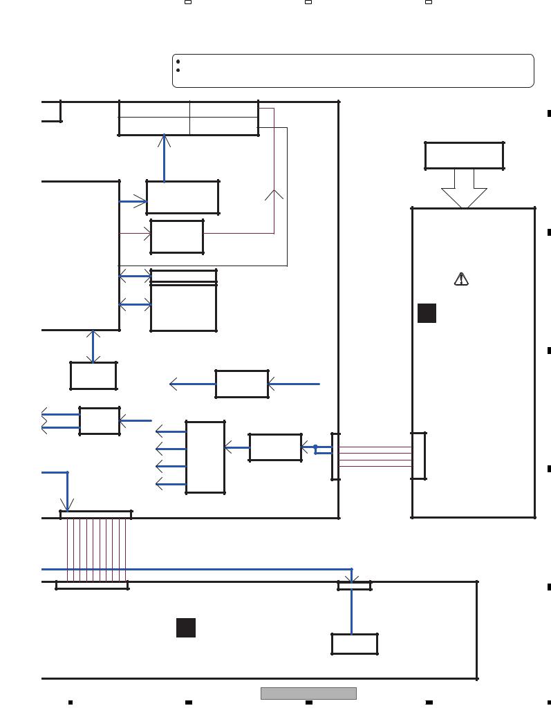
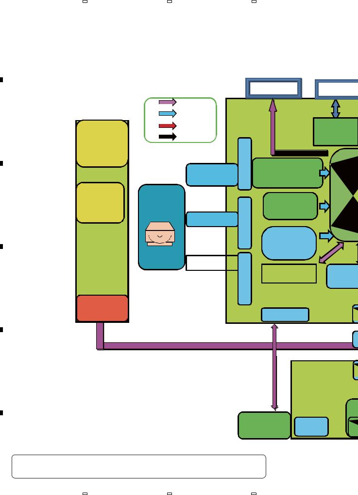
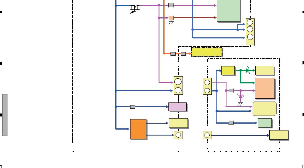
4.2 BLOCK DIAGRAM
A
BDP-160 Block Diagram:
B
C
D
E
D |
POWER BOARD ASSY |
Data |
||
|
PSU BOARD |
Control |
||
|
|
Power |
||
|
AC IN |
Others |
||
100,110~22 |
|
|
|
|
|
0Vac |
|
|
RF SIGNAL |
|
|
|
|
45PIN FFC |
|
POWER |
BD |
SPINDLE&SL |
|
|
|
ED |
||
|
manageme |
LOADER |
|
|
|
|
MOTOR |
||
|
nt IC |
|
|
|
|
|
|
|
9PIN FFC |
|
|
|
|
TRAY |
|
|
|
|
IN/OUT |
|
|
TBL3000+ |
|
MOTOR |
|
|
|
|
|
|
|
|
|
|
|
|
SANYO480 |
|
4PIN |
|
|
|
|
|
LOADER ASSY (08-LTCBS9-222160)
12V
USB LAN
|
|
|
|
|
TRANSFO |
|
|
|
|
|
|
RMER |
|
OPU |
|
|
|
|
|
|
|
|
|
|
|
|
|
|
OSCILLATOR |
|
|
|||
|
|
|
|
|||
TRAVERSE |
(27MHz30ppm) |
|
|
|||
|
|
RESET |
|
|
||
|
|
|
|
|
||
|
|
|
MOTOR |
|
|
|
|
|
|
DRIVER |
|
|
|
TRAY |
|
|
|
|
|
|
|
A CH DDR3 |
|
|
B CH D |
||
|
|
|
|
|||
|
|
|
|
|
|
|
|
|
|
|
|
|
|
|
|
|
MAIN BOARD |
|
|
|
|
|
|
4PINS |
|
|
|
Front BOARD
WIFI port |
IR |
F
 When ordering service parts, be sure to refer to "EXPLODED VIEWS and PARTS LIST" or "PCB PARTS LIST".
  The > mark found on some component parts indicates the importance of the safety factor of the part. Therefore, when replacing, be sure to use parts of identical designation.
10 |
BDP-160-K |
|
1 |
|
2 |
|
3 |
|
4 |
|
|
|
|
|
|

|
5 |
|
6 |
|
7 |
|
8 |
|
|
|
|
|
|
A
|
|
|
|
|
|
|
A |
MAIN BOARD ASSY |
|
|
|||
|
LAN |
|
|
HDMI |
|
|
COAXIAL/L/R |
||||||
|
|
|
|
|
|
|
|
|
|
|
|
|
|
|
|
|
|
HDMI |
|
|
Coaxial/L/R |
|
|||||
TRANSFO |
|
|
|
|
|
|
|
Amplifier |
|
|
|
|
|
|
|
|
|
|
|
|
|
|
|
|
|||
RMER |
|
|
|
|
|
|
|
|
1.2V |
|
5V |
||
|
|
|
|
|
|
|
|
|
|
|
|
||
|
|
|
|
|
|
|
|
|
|
|
|
||
|
|
|
|
|
|
|
|
|
|
|
|
||
|
|
|
|
|
|
|
|
|
|
|
1.5V |
DC- |
|
|
|
|
|
|
|
|
|
|
|
|
|||
|
MTK |
|
|
|
|
|
NAND |
|
|
|
|||
|
|
|
|
|
|
|
|
DC |
|
||||
|
|
|
|
|
|
FLASH |
|
3.3V |
|
||||
|
|
|
|
|
|
|
|
|
|||||
8560 |
|
|
|
|
|
|
3.3V_STBY |
|
|||||
USB_VCC |
|
|
12V_ |
|
|
||||||||
|
|
|
|
|
|
|
12V |
||||||
|
|
|
|
|
|
|
|
||||||
|
|
|
|
|
|
|
|
|
|
|
5V |
|
|
|
|
|
|
|
|
|
|
|
Power |
|
MOS |
|
|
|
|
|
|
|
|
|
|
|
|
5V_D |
|
||
|
|
|
|
|
|
|
|
|
switch |
|
|
|
|
|
|
|
|
|
|
|
9V |
|
|
12V |
|
|
|
|
|
|
|
|
|
|
|
|
|
|
|
||
|
B CH DDR3 |
|
|
JTAG |
LDO |
|
5V |
DC-DC |
12V |
||||
|
|
|
|
|
USB |
|
|||||||
|
|
|
|
|
|
||||||||
|
|
|
10PINS |
|
|
12V |
|
||||||
|
|
|
|
|
|
|
|
|
|
|
|
|
|
|
12V |
|
SPI |
|
5V |
IR |
USB |
|
|
|
|||
BOARD |
|
10 PINS |
|
USB |
|
|
|
||||||
VFD
LED |
KEYS |
USB port |
KEYS |
B FRONT BOARD ASSY
BDP-160-K
B
C
D
E
F
11
|
5 |
|
6 |
|
7 |
|
8 |
|
|
|
|
|
|
12
1
K-160-BDP 3 2
4
F |
|
|
E |
|
D |
|
C |
|
B |
BDP-160 |
|
|
|
|
|
|
|
|
|
|
|
CN503 |
XP15 |
|
U4 |
|
|
|
|
D552 |
L550 |
L5 |
L1 |
|
1. 2V |
|
|
||
12V |
12VFB1 |
|
|
A1. 2V |
|||||
|
|
1 |
|
5V |
|
|
|
||
|
|
1 |
DCDC |
|
|
|
|
|
|
|
3.3u |
|
|
2.2u |
|
|
|
|
|
|
2 |
2 |
Conv. |
|
|
|
1. 2V |
||
|
|
|
|
|
|
||||
|
|
U5 |
OPWRSB |
|
|
|
|
||
|
|
|
|
|
|
|
|
||
|
|
3 |
3 |
|
|
|
3. 3V_STBY |
|
|
|
|
|
|
|
|
|
|
||
|
|
4 |
4 |
|
|
|
|
|
|
|
|
|
|
|
|
CEC Circuit |
|
|
|
|
|
|
|
|
DCDC |
RESET |
|
U1 |
|
PW Board |
|
|
|
|
Circuit |
|
MT8560 |
||
|
|
|
|
Conv. |
|
||||
|
|
|
|
|
U4 |
|
|
|
|
C POWER BOARD ASSY |
|
|
L4 |
|
1. 5V |
|
|
||
|
|
|
|
|
|
||||
|
|
2.2u |
|
|
|
|
|||
|
|
|
|
|
|
|
|
|
|
|
|
|
|
|
OPWRSB |
|
|
|
|
|
|
|
|
|
L2 |
R23 |
3. 3V |
|
|
|
|
|
|
|
|
|
|
|
|
|
|
|
|
|
2.2u |
|
|
|
DDRIC_VREF |
|
|
|
|
|
|
3. 3V |
|
|
|
|
|
|
|
|
OPWRSB |
|
R36 |
|
|
|
|
|
|
|
|
|
|
R37 |
DDR_VREF |
|
|
|
|
|
|
|
|
|
|
|
|
|
|
|
|
|
|
|
U13 |
|
|
|
|
|
|
|
|
|
AS9632 AP |
|
|
|
|
|
|
|
|
|
U8 |
|
|
|
|
|
|
|
|
256MB NAND Flash |
|
|
|
|
|
|
|
|
FB20 |
|
|
|
|
|
|
|
|
|
D3.3V |
|
|
U10 1/2 |
VCC_D |
FB19 |
MVCC_T |
|
1.2V |
|
FB32 |
AVCC |
U409 |
|
|
|
TPIC2050G4 |
|
|
|
FB18 |
|
FTS Driver |
U10 2/2 |
+12V_D |
M12V_T |
|
|
|
|
|||
|
|
U9 |
|
|
1. 2V |
|
ASS1117 |
VCC_BD_LD |
|
|
|
|
|
|
|
|
|
|
|
|
|
|
|
|
|
|
|
|
|
|
|
|
|
A |
BLOCKPOWER 3.4 |
|
|
|
|
|
|
|
|
|
|
|
|
|
|
|
|
|
|
|
|
|
|
|
|
|
|||
|
|
|
|
|
|
|
1 |
|||||||||||||||||
|
|
|
|
|
|
|
|
|
|
|
|
|
|
|
|
|
|
|
|
|
|
|||
|
|
|
|
|
|
|
|
|
|
|
|
|
|
|
|
|
|
|
|
|
|
|||
|
|
|
|
|
|
|
|
|
|
|
|
|
|
|
|
|
|
|
|
|
|
|||
|
|
|
|
|
|
|
|
|
|
|
|
|
|
|
|
|
|
|
|
|
|
|||
|
|
|
|
|
|
|
|
|
|
|
|
|
|
|
|
|
|
|
|
|
|
|||
|
|
|
|
|
|
|
|
|
|
|
|
|
|
|
|
|
|
|
|
|
|
|||
|
|
|
|
|
|
|
|
|
|
|
|
|
|
|
|
|
|
|
|
|
|
|
|
|
|
|
|
|
|
|
|
|
|
|
|
|
|
|
|
|
|
|
|
|
|
|
|
|
|
|
|
|
|
|
|
|
|
|
|
|
|
|
|
|
|
|
|
|
|
|
|
|
|
|
|
|
|
|
|
|
|
|
|
|
|
|
|
|
|
|
|
|
|
|
|
|
|
|
|
|
|
|
|
|
|
|
|
|
|
|
|
|
|
|
|
|
|
|
|
|
|
|
|
|
|
|
|
|
|
|
|
|
|
|
|
|
|
|
|
|
|
|
|
|
|
|
|
|
|
|
|
|
|
|
|
|
|
|
|
|
|
|
|
|
|
|
|
|
|
|
|
|
|
|
|
|
|
|
|
|
|
|
|
|
|
|
|
|
|
|
|
|
|
|
|
|
|
|
|
|
|
|
|
|
|
|
|
|
|
|
|
|
|
|
|
|
|
|
|
|
|
|
|
|
|
|
|
|
|
|
|
|
|
|
|
|
|
|
|
|
|
|
|
|
|
|
|
|
|
|
|
|
|
|
|
|
|
|
|
|
|
|
|
|
|
|
|
|
|
|
|
|
|
|
|
|
|
|
|
|
|
|
|
|
|
|
|
|
|
|
|
|
|
|
|
|
|
|
|
|
|
|
|
|
|
|
|
|
|
|
|
|
|
|
|
|
|
|
|
|
|
|
|
|
|
|
|
|
|
|
|
|
|
|
|
|
|
|
|
|
|
|
|
|
|
|
|
|
|
|
|
|
|
|
|
|
|
|
|
|
|
|
|
|
|
|
|
|
|
|
|
|
|
|
|
|
|
|
|
|
|
|
|
|
|
|
|
|
|
|
|
|
|
|
|
|
DIAGRAM |
2 |
|
|
|
|
|
|
|
|
|
|
|
|
|
|
|
|
|
|
|
|
|
|
|
|||
|
|
|
|
|
|
|
|
|
|
|
|
|
|
|
|
|
|
|
|
|
|
|||
|
|
|
|
|
|
|
|
|
|
|
|
|
|
|
|
|
|
|
|
|
|
|||
|
|
|
|
|
|
|
|
|
|
|
|
|
|
|
|
|
|
|
|
|
|
|||
|
|
|
|
|
|
|
|
|
|
|
|
|
|
|
|
|
|
|
|
|
|
|||
|
|
|
|
|
|
|
|
|
|
|
|
|
|
|
|
|
|
|
|
|
|
|||
|
|
|
|
|
|
|
|
|
|
|
|
|
|
|
|
|
|
|
|
|
|
|||
|
|
|
|
|
|
|
|
|
|
|
|
|
|
|
|
|
|
|
|
|
|
|||
|
|
|
|
|
|
|
|
|
|
|
|
|
|
|
|
|
|
|
|
|
|
|||
|
|
|
|
|
|
|
|
|
|
|
|
|
|
|
|
|
|
|
|
|
|
|||
|
|
|
|
|
|
|
|
|
|
|
|
|
|
|
|
|
|
|
|
|
|
|
|
|
|
|
|
|
|
|
|
|
|
|
|
|
|
|
|
|
|
|
|
|
|
|
|
|
|
|
|
|
|
|
|
|
|
|
|
|
|
|
|
|
|
|
|
|
|
|
|
|
|
|
|
|
|
|
|
|
|
|
|
|
|
|
|
|
|
|
|
|
|
|
|
|
|
|
|
|
|
|
|
|
|
|
|
|
|
|
|
|
|
|
|
|
|
|
|
|
|
|
|
|
|
|
|
|
|
|
|
|
|
|
|
|
|
|
|
|
|
|
|
|
|
|
|
|
|
|
|
|
|
|
|
|
|
|
|
|
|
|
|
|
|
|
|
|
|
|
|
|
|
|
|
|
|
|
|
|
|
|
|
|
|
|
|
|
|
|
|
|
|
|
|
|
|
|
|
|
|
|
|
|
|
|
|
|
|
|
|
|
|
|
|
|
|
|
|
|
|
|
|
|
|
|
|
|
|
|
|
|
|
|
|
|
|
|
|
|
|
|
|
|
|
|
|
|
|
|
|
|
|
|
|
|
|
|
|
|
|
|
|
|
|
|
|
|
|
|
|
|
|
|
|
|
|
|
|
|
|
|
|
|
|
|
|
|
|
|
|
|
|
|
|
|
|
|
|
|
|
|
|
|
|
|
|
|
|
|
|
|
|
|
|
|
|
|
|
|
|
|
|
|
|
|
|
|
|
|
|
|
|
|
|
|
|
|
|
|
|
|
|
|
|
|
|
|
|
|
|
|
|
|
|
|
|
|
|
|
|
|
|
|
|
|
|
|
|
|
|
|
|
|
|
|
|
|
|
|
|
|
|
|
|
|
|
|
|
|
|
|
|
|
|
|
|
|
|
|
|
|
|
|
|
|
|
|
|
|
|
|
|
|
|
|
|
|
|
|
|
|
|
|
|
|
|
|
|
|
|
|
|
|
|
|
|
|
|
|
|
|
|
|
|
|
|
|
|
|
|
|
|
|
|
|
|
|
|
|
|
|
|
|
|
|
|
|
|
|
|
|
|
|
U2 |
|
DDR3-1333 1Gb |
|
DDR3 |
3 |
|
U3
DDR3-1333 2Gb
DDR3
4
XP7
9 |
5
K-160-BDP 7 6
U10 2/2 |
+12V_D |
FB18 |
M12V_T |
|
|
|
|
|
|
|
|
|
|
||||
|
|
U9 |
|
|
|
|
|
|
1. 2V |
ASS1117 VCC_BD_LD |
|
|
XP7 |
|
|||
|
|
|
|
|
|
|
|
|
|
|
|
|
|
|
|
9 |
|
|
|
|
|
|
VCC_HFM |
10 |
|
|
|
|
|
|
|
|
|
|
|
|
|
|
|
|
VCC_PDIC |
|
to Pickup |
|
|
|
|
|
|
30 |
|
||
|
|
|
|
|
|
|
|
|
|
3. 3V |
|
|
|
|
|
|
|
|
|
R973 |
FB21 |
WIFI Board |
|
|
|
|
|
|
|
|
|
|
|
|
|
|
|
|
XP1 |
|
XS135 |
|
ZD135 |
|
|
|
|
|
|
VCC |
-24V_D |
|
VFD135 |
|
|
|
|
|
Boost |
|
FL Display |
|
|
|
|
|
|
|
|
|
|
|
+12V_D |
16 |
|
+12V_D |
|
|
||
|
|
|
|
|
|
|||
|
|
|
|
to Front |
9 |
R154 |
|
U135 |
|
|
|
|
|
R155 |
+5V |
||
|
VCC |
|
|
|
|
PT6312 |
||
|
|
15 |
|
6 |
|
|||
|
|
|
|
|
|
FL Driver |
||
|
|
|
|
|
1k |
|
||
|
|
|
|
|
VCC |
ZD136 |
|
|
|
|
|
|
|
|
|
||
F1 |
HDMI_VCC |
J1 |
HDMI |
|
|
|
|
|
|
|
|
|
FL_AC Circuit |
||||
|
|
Terminal |
|
|
||||
U11 |
|
|
|
|
|
|
|
|
G556B1 |
USB_VCC0 |
|
P2 |
|
|
R167 |
|
IR1 |
|
|
|
|
|
||||
|
|
|
|
|
|
|||
High- |
|
USB Terminal |
XS221 |
100 |
|
IRM |
||
Side |
|
|
|
|
|
|
||
|
|
|
|
|
|
|
||
SW |
USB_VCC1 |
|
1 |
to Front |
VCC_USB |
|
|
P221 |
|
|
|
USB |
4 |
|
|
USB Terminal |
|
|
|
|
|
|
|
|
||
|
|
|
XP17 |
|
|
|
|
|
|
Main Board |
|
|
|
|
|
|
|
|
|
|
|
|
|
|
|
|
FV Board |
|
|||||||||||||||||||||||||||||||||||||||||||||||||||||||||||||||
|
|
|
|
|
|
|
|
|
|
|
|
|
|
|
|
|
|
|||||||||||||||||||||||||||||||||||||||||||||||||||||||||||||||||
|
|
|
|
|
|
|
|
|
|
|
|
|
|
|
||||||||||||||||||||||||||||||||||||||||||||||||||||||||||||||||||||
|
|
|
|
|
|
|
|
|
|
|
|
|
|
|
|
|
|
|
|
|
|
|
|
|
|
|
|
|
|
|
|
|
|
|
|
|
|
|
|
|
|
|
|
|
|
|
|
|
|
|
|
|
|
|
|
|
|
|
|
|
|
|
|
|
|
|
|
|
|
|
|
|
|
|
|
|
|
|
|
|
|
|
|
|
|
|
|
|
|
|
|
|
|
|
|
|
|
|
|
MAIN BOARD ASSY |
|
|
|
|
|
|
|
|
|
|
|
|
|
|
|
|
|
|
|
||||||||||||||||||||||||||||||||||||||||||||||
|
|
|
|
|
|
|
|
|
|
|
|
|
|
|
|
|
|
|
|
|
|
|
|
|
|
|
|
|
B |
|
||||||||||||||||||||||||||||||||||||||||||||||||||||
|
|
|
|
|
|
|
|
|
|
|
|
|
A |
|
|
|
|
|
|
|
|
|
|
|
|
|
|
|
|
FRONT BOARD ASSY |
|
|||||||||||||||||||||||||||||||||||||||||||||||||||
|
|
|
|
|
|
|
|
|
|
|
|
|
|
|
|
|
|
|
|
|
|
|
|
|
|
|
|
|
|
|
|
|
|
|
|
|
|
|
|
|
|
|
|
|
|
|
|
|
|
|
|
|
|
|
|
|
|
|
|
|
|
|
|
|
|
|
|
|
|
|
|
|
|
|
|
|
|
|
|
|
|
|
5
6
7
|
|
|
|
8 |
8 |
||
13 |
|
|
|
|
|
|
|
|
|
|
|
|
|
F |
|
E |
|
D |
|
C |
|
B |
|
A |
|
|
|
|
|
|
|
|
||||||
|
1 |
|
2 |
|
3 |
|
|
|
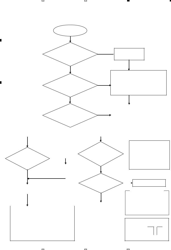
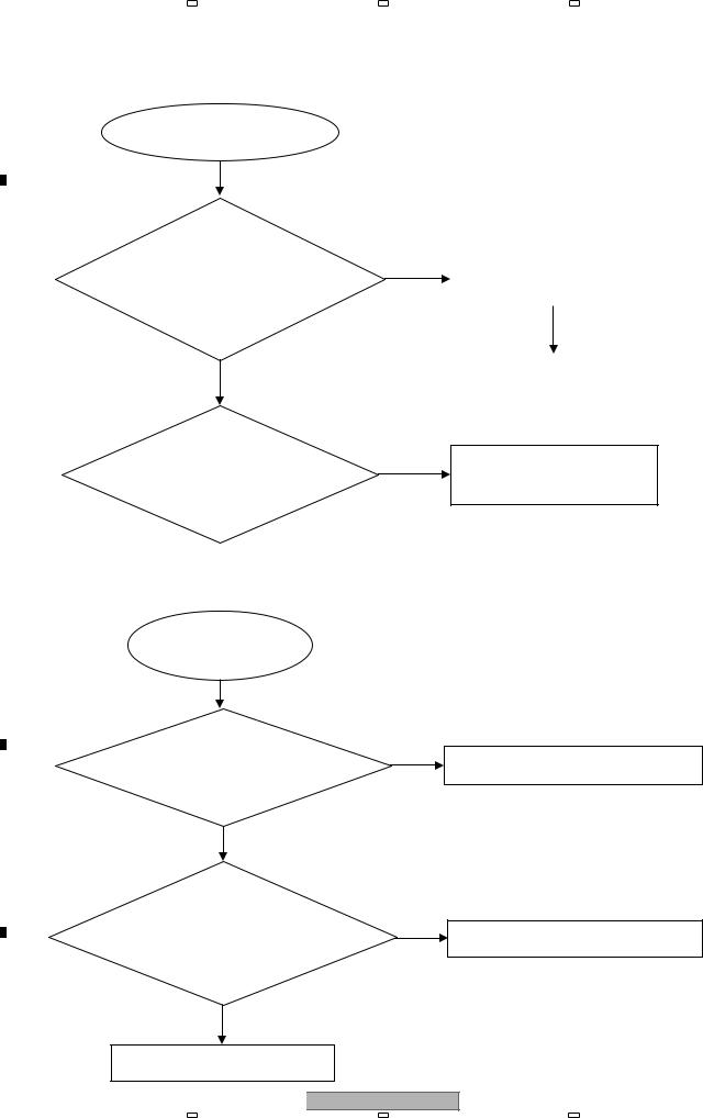
5. DIAGNOSIS
5.1 DIAGNOSIS FLOWCHART
A 1) Power does not turn on
Power does not turn on
Check whether either the remote controller or the Main Unit power button can not turn
on the power supply.
B
Both or only the Main
Unit power button
Check whether the voltage of XP1(pin 1 and
pin 2) on the MAIN BOARD ASSY are 12 V
Yes
Only the
remote controller
No
C
4
Go to the flowchart for  “Remote control does
not work”
Check whether there is no problem in the connector contact between the POWER BOARD ASSY and the MAIN BOARD ASSY.
If there is no problem, please replace the POWER BOARD ASSY.
|
|
Check whether the |
|
|
Check whether there is no problem in the |
|
|
|
No |
connector contact between the MAIN |
|||
|
|
voltage of XS135(pin 6) on the |
||||
|
|
BOARD ASSY and the FRONT BOARD |
||||
|
|
FRONT BOARD ASSY is 5 V and |
|
|
||
|
|
|
|
ASSY. |
||
|
|
X135(pin 9) is 12 V |
|
|
||
|
|
|
|
If there is no problem, please replace |
||
|
|
|
|
|
|
|
|
When the remote controller and the Main Yes |
|
|
|
the MAIN BOARD ASSY. |
|
|
|
|
|
|||
|
|
|
|
|
||
|
When only the Main Unit power |
|||||
|
Unit power button cannot turn on the power |
button is not active to turn on the power |
||||
|
|
|
|
|
|
|
D |
|
|
|
|
|
|
|
|
|
|
|
|
|
|
|
|
|
|
|
|
|
|
|
|
|
|
Check whether the |
|
|
|
|
Check whether the |
|
Yes |
voltage of XP1(pin 1) on the |
||||||
|
|
|
|
|
|
SWITCH BOARD |
|||||||
|
|
voltage of XP18(pin 10) on the |
|
|
|||||||||
|
|
|
|
|
|
|
|
|
ASSY is 5V |
||||
|
|
|
MAIN BOARD ASSY |
|
|
|
|
|
|
|
|||
|
|
|
|
|
|
|
|
|
|
|
|||
|
|
|
|
is 0V |
|
|
|
|
|
|
|
|
|
|
|
|
|
|
Replace K138 on the |
|
Yes |
||||||
|
|
|
|||||||||||
|
|
|
|
|
|
|
|||||||
|
|
|
|
No |
|
FRONT BOARD ASSY |
|
|
|||||
|
|
|
|
|
|
|
|
|
|
|
|||
|
|
|
|
When there is no change |
|
|
Check whether SW1 |
||||||
|
|
|
|
|
|
|
|
|
|
|
|
|
|
|
|
|
|
|
|
|
|
|
|
|
|
on the SWITCH BOARD ASSY |
|
E |
|
|
Replace the FRONT BOARD |
|
|
|
|
|
operation is |
||||
|
|
|
|
|
|
|
normal |
||||||
|
|
|
|
ASSY |
|
|
|
|
|
|
|
||
|
|
|
|
|
|
|
|
|
|
|
|
||
|
|
|
|
|
|
|
|
|
|
|
|
|
Yes |
|
|
|
|
When there is no change |
|||||||||
|
|
|
|
|
|
||||||||
|
|
|
|
|
|
|
|
|
|
|
|
|
|
|
|
|
|
|
|
|
|
|
|
|
|
|
Replace the SWITCH |
|
|
|
|
|
|
|
|
|
|
|
|
||
|
|
|
Replace the MAIN BOARD ASSY |
|
BOARD ASSY |
||||||||
|
|
|
|||||||||||
|
|
||||||||||||
|
|
|
|
|
|
|
|
|
|
|
|
|
|
*Because a failure in the hardware reset circuit may be the cause of the inactive power supply, please replace the MAIN BOARD ASSY.
About hardware reset sircuit.
F(A circuit for providing a function to reset the product by inserting a bar in the small hole on the front panel)
Check whether there is no problem in the connector
No contact between the FRONT
 BOARD ASSY and the SWITCH BOARD ASSY.
If there is no problem, please replace the FRONT BOARD ASSY.
No
 Replace SW1
How to check the SW1
1.Check the conduction with a tester after turning off the power.
2.Check the waveform of the XP18 (pin 7:POWER) on the MAIN BOARD ASSY.
Waveform (POWER)
SW1 OFF : 5V
SW1 ON : 0V 


 (GND)
(GND)
14 |
BDP-160-K |
|
1 |
|
2 |
|
3 |
|
4 |
|
|
|
|
|
|
|
5 |
|
6 |
|
7 |
|
8 |
|
|
|
|
|
|
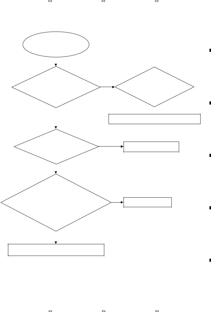
2) No display on VFD, and buttons do not work |
A |
|
No display on VFD, and buttons do not work
Yes
Check every supply voltage on the MAIN BOARD ASSY is normal
Yes
Check the FRONT BOARD ASSY signals VCLK, VSTB, VD (XS135 : pin 1,2,3)
Yes
B
No
Check if U10 are soldering normally on the MAIN BOARD ASSY
No 
Resolder Q150 and U25.
If still same situation, replace the MAIN BOARD ASSY
C
No
Check the connect line is OK
D
1.Check whether the bad solder exists U135 and pins of VFD on the FRONT
BOARD ASSY No
Correct connection
2.Check whether the circuit
connected to K135, K136, K137, and K138 are broken.
Yes
Replace K135, K136, K137 and K138.
If still same situation, replace the FRONT BOARD ASSY.
E
F
BDP-160-K |
15 |
|
5 |
|
6 |
|
7 |
|
8 |
|
|
|
|
|
|
|
1 |
|
2 |
|
3 |
|
4 |
|
|
|
|
|
|
A 3) No analog audio output (video output is normal)
No analog audio output
Yes
|
|
Check whether the audio |
|
|
|
|
|
Check the U13 power supply |
|
B |
signal is right from the |
No |
||
|
|
|
||
|
|
U13 (pin 3 and pin 12) on the |
|
(U12 : pin 9 = 3.3V) |
|
|
MAIN BOARD ASSY |
|
|
|
|
|
NO |
|
|
|
Yes |
|
|
|
|
|
Replace MAIN BOARD ASSY |
|
|
|
|
||
|
|
|
|
|
|
|
|
|
|
C |
Check If R76 and R108 are |
No |
|
|
|
soldering normally on the MAIN |
|
|
|
BOARD ASSY |
|
|
|
|
|
|
|
|
|
4) Remote control does not work
Remote control
D |
does not work |
|
|
|
Yes |
Check whether the remote
No
controller’s battery is exhausted or not.
Yes
E
Check the IR1(ET3050)
power supply is OK, No IR1(pin 3) is about 3V
Yes
F
Replace the FRONT BOARD ASSY
16 |
BDP-160-K |
Resolder R310 and R311.
If still same situation, replace the MAIN BOARD ASSY
Replace the battery for remote controller
Check the VCC line(net) on the FRONT BOARD ASSY
|
1 |
|
2 |
|
3 |
|
4 |
|
|
|
|
|
|
 Loading...