


Service
Manual
ORDER NO.
CRT2379
7 INCH WIDE AV SYSTEM DISPLAY/CD PLAYER
AVX-P7000CD UC
AVX-P7000CD EW
AVX-P7000CD ES
NOTE:
-See the separate manual CX-680(CRT2216) for the cassette mechanism description.
-The CD mechanism assy employed in this model is one of H1 series.
-For the details of the LCD module and the drive mech unit, refer to the separate manual CRT2276.
CONTENTS
1. |
SAFETY INFORMATION............................................ |
2 |
7. |
GENERAL INFORMATION....................................... |
48 |
2. |
EXPLODED VIEWS AND PARTS LIST ...................... |
3 |
|
7.1DIAGNOSIS ........................................................ |
48 |
3. |
BLOCK DIAGRAM AND SCHEMATIC DIAGRAM .. |
12 |
|
7.1.1 TEST MODE ............................................. |
48 |
4. |
PCB CONNECTION DIAGRAM................................ |
31 |
|
7.1.2 DISASSEMBLY......................................... |
52 |
5. |
ELECTRICAL PARTS LIST........................................ |
41 |
|
7.1.3 PCB LOCATIONS...................................... |
59 |
6. |
ADJUSTMENT ......................................................... |
46 |
|
7.2IC ......................................................................... |
60 |
|
|
|
|
7.3MECHANISM DESCRIPTIONS........................... |
66 |
|
|
|
8. |
OPERATIONS AND SPECIFICATIONS.................... |
70 |
PIONEER ELECTRONIC CORPORATION |
4-1, Meguro 1-Chome, Meguro-ku, Tokyo 153-8654, Japan |
PIONEER ELECTRONICS SERVICE INC. P.O.Box 1760, Long Beach, CA 90801-1760 U.S.A. |
|
PIONEER ELECTRONIC [EUROPE] N.V. Haven 1087 Keetberglaan 1, 9120 Melsele, Belgium
PIONEER ELECTRONICS ASIACENTRE PTE.LTD. 253 Alexandra Road, #04-01, Singapore 159936
C PIONEER ELECTRONIC CORPORATION 1999
K-ZZU. APR. 1999 Printed in Japan
AVX-P7000CD
- CD Player Service Precautions
1.For pickup unit(CXX1290) handling, please refer to"Disassembly"(see page 55).
During replacement, handling precautions shall be taken to prevent an electrostatic discharge(protection by a short pin).
2.During disassembly, be sure to turn the power off since an internal IC might be destroyed when a connector is plugged or unplugged.
3.Please checking the grating after changing the service pickup unit(see page 46).
1. SAFETY INFORMATION
CAUTION
This service manual is intended for qualified service technicians; it is not meant for the casual do-it-yourselfer. Qualified technicians have the necessary test equipment and tools, and have been trained to properly and safely repair complex products such as those covered by this manual.
Improperly performed repairs can adversely affect the safety and reliability of the product and may void the warranty. If you are not qualified to perform the repair of this product properly and safely, you should mot risk trying to do so and refer the repair to a qualified service technician.
WARNING
This product contains lead in solder and certain electrical parts contain chemicals which are known to the state of California to cause cancer, birth defects or other reproductive harm.
Health & Safety Code Section 25249.6 - Proposition 65
1. Safety Precautions for those who Service this Unit.
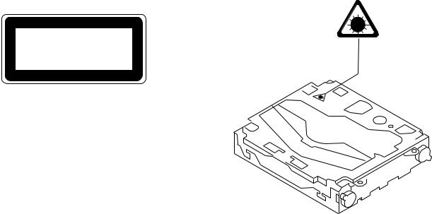
•When checking or adjusting the emitting power of the laser diode exercise caution in order to get safe, reliable results.
Caution:
1.During repair or tests, minimum distance of 13cm from the focus lens must be kept.
2.During repair or tests, do not view laser beam for 10 seconds or longer.
2.A “CLASS 1 LASER PRODUCT” label is affixed to the rear of the player.
3.The triangular label is attached to the mechanism unit frame.
CLASS 1
LASER PRODUCT
4. Specifications of Laser Diode
Specifications of laser radiation fields to which human access is possible during service. Wavelength = 800 nanometers
2

AVX-P7000CD
2. EXPLODED VIEWS AND PARTS LIST
2.1 PACKING
|
|
16 |
|
|
|
17 |
14 |
|
|
|
|
9 |
11 |
|
20 |
19

 10
10
13 |
|
12 |
18 |
|
7 |
3 |
|
6 |
|
1 |
|
5 |
|
|
15 |
8 |
|
|
|
|
4 |
21 |
2
3
AVX-P7000CD
NOTE:
-Parts marked by “*”are generally unavailable because they are not in our Master Spare Parts List.
-Screws adjacent to mark on the product are used for disassembly.
-PACKING SECTION PARTS LIST
|
|
|
|
Part No. |
|
Mark No. Description |
AVX-P7000CD/UC |
AVX-P7000CD/EW |
AVX-P7000CD/ES |
||
|
1 |
Carton |
CHG3804 |
CHG3802 |
CHG3803 |
|
2 |
Contain Box |
CHL3804 |
CHL3802 |
CHL3803 |
|
3 |
Protector |
CHP2163 |
CHP2163 |
CHP2163 |
|
4 |
Protector |
CHP2164 |
CHP2164 |
CHP2164 |
|
5 |
Cord Assy |
CDE5930 |
CDE5930 |
CDE5930 |
|
6 |
Cord Assy |
CDE5908 |
CDE5908 |
CDE5908 |
|
7 |
Cord Assy |
CDE6033 |
CDE6033 |
CDE6033 |
|
8 |
Speaker Assy |
CXB4203 |
CXB4203 |
Not used |
|
9 |
Accessory Assy |
CEA2547 |
CEA2547 |
CEA2547 |
|
10 |
Screw |
CBA1002 |
CBA1002 |
CBA1002 |
|
11 |
Handle |
CNC5395 |
CNC5395 |
CNC5395 |
|
12 |
Bush |
CNV1917 |
CNV1917 |
CNV1917 |
* |
13 |
Polyethylene Bag |
E36-615 |
E36-615 |
E36-615 |
* |
14 |
Polyethylene Bag |
CEG-127 |
CEG-127 |
CEG-127 |
|
15 |
Polyethylene Bag |
CEG1173 |
CEG1042 |
CEG1042 |
|
16-1 |
Owner's Manual |
CRD3011 |
CRD3013 |
CRD3044 |
|
16-2 |
Owner's Manual |
Not used |
CRD3014 |
Not used |
|
16-3 |
Installation Manual |
Not used |
CRD3015 |
Not used |
* |
16-4 |
Warranty Card |
Not used |
CRY1087 |
Not used |
* |
16-5 |
Card |
ARY1048 |
Not used |
Not used |
|
17 |
Polyethylene Bag |
Not used |
CEG1116 |
Not used |
|
18 |
Screw |
CBA1468 |
CBA1468 |
CBA1468 |
|
19 |
Screw |
CMZ50P060FMC |
CMZ50P060FMC |
CMZ50P060FMC |
|
20 |
Screw |
BMZ50P060FMC |
BMZ50P060FMC |
BMZ50P060FMC |
|
21 |
Cord Assy |
CDE5939 |
CDE5939 |
CDE5939 |
|
|
|
|
|
|
- Owner's Manual and Installation Manual
Model |
Part No. |
Language |
|
|
|
AVX-P7000CD/UC |
CRD3011 |
English,French |
|
|
|
AVX-P7000CD/EW |
CRD3013 |
English,Spanish,German |
|
|
|
|
CRD3014 |
French,Italian,Dutch |
|
|
|
|
CRD3015 |
English,Spanish,Dutch,German,French,Italian |
|
|
|
AVX-P7000CD/ES |
CRD3044 |
English,Spanish |
|
|
|
4

AVX-P7000CD
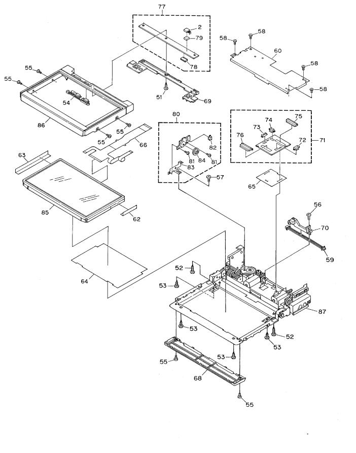
2.2 EXTERIOR(1/2)
5
AVX-P7000CD
6
AVX-P7000CD
(1) EXTERIOR SECTION PARTS LIST
Mark No. Description |
Part No. |
|
Mark No. Description |
Part No. |
||
1 |
Screw |
BMZ26P050FZK |
46 |
IC(IC1) |
SBX8035-H |
|
2 |
IC(IC24) |
PNA4603H00LB |
47 |
Spacer |
CNM6200 |
|
3 |
Screw |
BSZ26P040FMC |
48 |
Rack |
CNV5737 |
|
4 |
Screw |
BSZ30P040FMC |
49 |
Rack |
CNV5738 |
|
5 |
Transistor(Q1801,Q1809) |
2SD2396 |
50 |
Chassis Unit |
CXB3769 |
|
6 |
Screw(M2x2) |
CBA1487 |
51 |
Screw |
BPZ20P100FMC |
|
7 |
Connector |
CDE5925 |
52 |
Screw |
BPZ20P120FZK |
|
8 |
Cord Assy |
CDE5930 |
53 |
Screw |
BPZ26P050FMC |
|
9 |
Fuse(4A) |
CEK1001 |
54 |
Button(ANGEL,WIDE) |
See Contrast table(2) |
|
10 |
Cap |
CNS1472 |
55 |
Screw |
See Contrast table(2) |
|
11 |
Screw |
UFZ26P030FMC |
56 |
Screw |
CBA1481 |
|
12 |
Resistor |
RS1/2PMF102J |
57 |
Screw |
CBA1482 |
|
13 |
Case |
CNB2458 |
58 |
Screw |
CBA1484 |
|
14 |
Holder |
CNC6798 |
59 |
Connector |
CDE5924 |
|
15 |
Bracket |
CNC8260 |
60 |
Case |
CNC8405 |
|
16 |
Bracket |
CNC8261 |
61 |
••••• |
|
|
17 |
Holder |
CNC8359 |
62 |
Insulator |
CNM6314 |
|
18 |
Holder |
CNC8387 |
63 |
Insulator |
CNM6315 |
|
19 |
Insulator |
CNM6199 |
64 |
Insulator |
CNM6339 |
|
20 |
Insulator |
CNM6201 |
65 |
Insulator |
CNM6340 |
|
21 |
PCB |
CNP5539 |
66 |
PCB |
CNP5449 |
|
22 |
Panel |
See Contrast table(2) |
67 |
PCB |
CNP5451 |
|
23 |
Cord Assy |
See Contrast table(2) |
68 |
Cover |
See Contrast table(2) |
|
24 |
Cord Assy |
See Contrast table(2) |
69 |
Holder |
CNV5744 |
|
25 |
Cord Assy |
CDE6138 |
70 |
Holder |
CNV5842 |
|
26 |
System Micro Computer Unit |
See Contrast table(2) |
71 |
Relay Unit |
CWM6425 |
|
27 |
Screw |
ASZ26P100FMC |
72 |
Connector(CN52) |
CKS3124 |
|
28 |
Clamper |
CEF1009 |
73 |
Connector(CN53) |
CKS3124 |
|
29 |
Plug(CN1801) |
CKS-461 |
74 |
Connector(CN57) |
CKS3125 |
|
30 |
Connector(CN1604) |
CKS3125 |
75 |
Connector(CN51) |
CKS3802 |
|
31 |
Connector(CN1601) |
CKS4064 |
76 |
Connector(CN55) |
CKS4132 |
|
32 |
Connector(CN1602) |
CKS4064 |
77 |
LCD Keyboard Unit |
See Contrast table(2) |
|
33 |
Connector(CN1603) |
CKS4066 |
78 |
Connector(CN21) |
CKS4057 |
|
34 |
Holder |
CNC8259 |
79 |
Spacer |
CNM6271 |
|
35 |
Heat Sink |
CNC8262 |
80 |
Encoder Unit |
CWM6587 |
|
36 |
CD Micro Computer Unit |
CWM6444 |
81 |
Screw |
CBA1483 |
|
37 |
Connector(CN2601) |
CKS1968 |
82 |
Connector(CN56) |
CKS3125 |
|
38 |
Connector(CN2002) |
CKS3132 |
83 |
Bracket |
CNC8406 |
|
39 |
Connector(CN2001) |
CKS3133 |
84 |
Gear |
CNV5841 |
|
40 |
Connector(CN2901) |
CKS3133 |
85 |
LCD Module |
CWX2389 |
|
41 |
Connector(CN2902) |
CKS3971 |
86 |
Grille Unit |
See Contrast table(2) |
|
42 |
Connector(CN2602) |
CKS4054 |
87 |
Drive Mechanism Unit |
See Contrast table(2) |
|
43 |
Connector(CN2603) |
CKS4063 |
88 |
Screw |
BPZ20P060FMC |
|
44 |
Connector(CN2604) |
CKS4063 |
89 |
Button |
CAC6025 |
|
45 |
Connector(CN2605) |
CKS4065 |
90 |
Button |
CAC6026 |
|
7
AVX-P7000CD
Mark No. Description |
Part No. |
||
* |
91 |
Cover |
CNM6470 |
|
92 |
Panel Keyboard Unit |
See Contrast table(2) |
|
93 |
Connector(CN1) |
CKS4054 |
|
94 |
Spacer |
CNM6272 |
|
95 |
Grille Unit |
See Contrast table(2) |
|
96 |
Detach Grille Assy |
See Contrast table(2) |
|
97 |
Screw |
BPZ20P060FZK |
|
98 |
Button(Detach) |
See Contrast table(2) |
|
99 |
Button(+) |
See Contrast table(2) |
|
100 |
Button(-) |
See Contrast table(2) |
|
101 |
Button(CD EJECT) |
See Contrast table(2) |
|
102 |
Button(OPEN/CLOSE) |
See Contrast table(2) |
|
103 |
Button(RESET) |
See Contrast table(2) |
|
104 |
Spring |
CBH2239 |
|
105 |
Spring |
CBH2302 |
|
106 |
Cover |
See Contrast table(2) |
|
107 |
Grille |
See Contrast table(2) |
|
108 |
CD Mechanism Module(H1) |
CXK5141 |
|
109 |
Cord Assy |
See Contrast table(2) |
|
110 |
Cord Assy |
See Contrast table(2) |
8
AVX-P7000CD
(2) CONTRAST TABLE
AVX-P7000CD/UC , AVX-P7000CD/EW and AVX-P7000CD/ES are constructed the same except for the
following:
|
|
|
Part No. |
|
Mark No. |
Description |
AVX-P7000CD/UC |
AVX-P7000CD/EW |
AVX-P7000CD/ES |
22 |
Panel |
CNS5427 |
CNS5427 |
CNS5550 |
23 |
Cord Assy |
CDE5934 |
CDE5934 |
Not used |
24 |
Cord Assy |
CDE6030 |
CDE6030 |
Not Used |
26 |
System Micro Computer Unit |
CWM6430 |
CWM6431 |
CWM6430 |
54 |
Button |
CAC6107 |
CAC6107 |
CAC6024 |
55 |
Screw |
CBA1477 |
CBA1477 |
CBA1475 |
68 |
Cover |
CNS5499 |
CNS5499 |
CNS5420 |
77 |
LCD Keyboard Unit |
CWM6426 |
CWM6427 |
CWM6426 |
86 |
Grille Unit |
CXB4533 |
CXB4533 |
CXB4534 |
87 |
Drive Mechanism Unit |
CXB4204 |
CXB4204 |
CXB4205 |
92 |
Panel Keyboard Unit |
CWM6439 |
CWM6438 |
CWM6439 |
95 |
Grille Unit |
CXB4554 |
CXB4554 |
CXB4551 |
96 |
Detach Grille Assy |
CXB4227 |
CXB4226 |
CXB4228 |
98 |
Button |
CAC6031 |
CAC6031 |
CAC6151 |
99 |
Button |
CAC6108 |
CAC6108 |
CAC6027 |
100 |
Button |
CAC6109 |
CAC6109 |
CAC6028 |
101 |
Button |
CAC6110 |
CAC6110 |
CAC6029 |
102 |
Button |
CAC6111 |
CAC6111 |
CAC6030 |
103 |
Button |
CAC6112 |
CAC6112 |
CAC6032 |
106 |
Cover |
CNS5503 |
CNS5503 |
CNS5424 |
107 |
Grille |
CNS5504 |
CNS5502 |
CNS5505 |
109 |
Cord Assy |
Not used |
Not used |
CDE5937 |
110 |
Cord Assy |
Not used |
Not used |
CDE6070 |
9
AVX-P7000CD
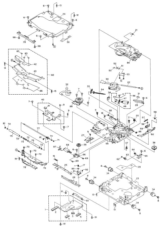
2.3 CD MECHANISM MODULE
10
AVX-P7000CD
- CD MECHANISM MODULE SECTION PARTS LIST
Mark No. |
Description |
Part No. |
|
Mark No. |
Description |
Part No. |
|
|
1 |
Control Unit |
CWX2350 |
|
51 |
Spring |
CBH2039 |
|
2 |
Connector(CN701) |
CKS1968 |
52 |
Rack |
CNV5471 |
|
|
3 |
Connector(CN802) |
CKS3477 |
53 |
Bracket Unit |
CXB1674 |
|
|
4 |
Connector(CN801) |
CKS3481 |
54 |
Screw Unit |
CXB1676 |
|
|
5 |
Connector(CN101) |
CKS3486 |
55 |
Chassis Unit |
CXB3042 |
|
|
6 |
Screw |
BMZ20P025FMC |
56 |
Washer |
CBF1038 |
|
|
7 |
Screw(M2×2.5) |
CBA1037 |
57 |
Spring |
CBH2035 |
|
|
8 |
Screw(M2×5) |
CBA1296 |
58 |
Spring |
CBH2036 |
|
|
9 |
Screw(M2×1.8) |
CBA1340 |
59 |
Lever |
CNV5078 |
|
|
10 |
Screw(M2×4) |
CBA1362 |
60 |
Lever Unit |
CXB3207 |
|
|
11 |
Screw(M2×9) |
CBA1440 |
61 |
Arm Unit |
CXB1680 |
|
|
12 |
Spring |
CBH2029 |
62 |
Washer |
CBF1038 |
|
|
13 |
Spring |
CBH2030 |
63 |
Gear |
CNV5083 |
|
|
14 |
Spring |
CBH2031 |
64 |
Gear |
CNV5084 |
|
|
15 |
Spring |
CBH2032 |
65 |
Bracket Unit |
CXB1682 |
|
|
16 |
Spring |
CBH2033 |
66 |
Bracket |
CNC7292 |
|
|
17 |
Spring |
CBH2207 |
67 |
••••• |
|
|
|
18 |
Spring |
CBH2040 |
68 |
LOAD Motor Unit(M2) |
CXB1684 |
|
|
19 |
Spring |
CBH2041 |
69 |
Screw |
JFZ14P020FNI |
|
|
20 |
Spring |
CBH2042 |
70 |
Screw(M2×2) |
CBA1451 |
|
|
21 |
Spring |
CBH2052 |
71 |
Washer |
CBF1037 |
|
|
22 |
Shaft |
CLA3232 |
72 |
Washer |
CBF1060 |
|
|
23 |
Frame |
CNC8264 |
73 |
Screw |
CBH2170 |
|
|
24 |
Frame |
CNC7286 |
74 |
Roller |
CLA3222 |
|
|
25 |
Lever |
CNC7288 |
75 |
Roller |
CNV3412 |
|
|
26 |
Lever |
CNC7289 |
76 |
Arm |
CNV5075 |
|
|
27 |
Cover |
CNC7294 |
77 |
Roller Gear Unit |
CXB1686 |
|
|
28 |
Cover |
CNC7304 |
78 |
Bracket Unit |
CXB2627 |
|
|
29 |
Sheet |
CNM5401 |
79 |
••••• |
|
|
|
30 |
Sheet |
CNM5402 |
80 |
••••• |
|
|
|
31 |
Sheet |
CNM5814 |
81 |
Washer |
YE20FUC |
|
|
32 |
PCB |
CNP4854 |
82 |
Guide Arm Assy |
CXB1688 |
|
|
33 |
Belt |
CNT1082 |
83 |
Photo-transistor(P1-3) |
CPT-230S-X |
|
|
34 |
Damper |
CNV5855 |
84 |
Clamp Arm Assy |
CXB3137 |
|
|
35 |
Gear |
CNV5080 |
85 |
••••• |
|
|
|
36 |
Gear |
CNV5081 |
* 86 |
Sheet |
CNM5398 |
|
|
37 |
Gear |
CNV5082 |
87 |
••••• |
|
|
|
38 |
Holder |
CNV5098 |
88 |
Motor(M3) |
CXM1129 |
|
|
39 |
Guide |
CNV5352 |
89 |
Washer |
YE25FUC |
|
|
40 |
Mechanism FPC Unit |
CWX2191 |
90 |
Pickup Unit(Service) |
CXX1290 |
|
|
41 |
Connector |
CKS3767 |
91 |
Screw |
IMS20P035FMC |
|
* |
42 |
PCB |
CNP4852 |
92 |
Spring |
CBH2206 |
|
* |
43 |
Arm |
CNC7287 |
93 |
Bracket |
CNC7977 |
|
|
44 |
••••• |
|
94 |
••••• |
|
|
|
45 |
••••• |
|
95 |
Sheet |
CNM6055 |
|
|
46 |
••••• |
|
96 |
CRG Motor Assy(M1) |
CXB1670 |
|
|
47 |
Bracket |
CNC7300 |
97 |
Spring |
CBL1412 |
|
* |
48 |
CRG Motor Unit |
CXB1671 |
98 |
Screw |
IMS20P025FMC |
|
|
49 |
Screw |
JFZ14P020FNI |
|
|
|
|
|
50 |
Washer |
CBF1037 |
|
|
|
|
11
AVX-P7000CD
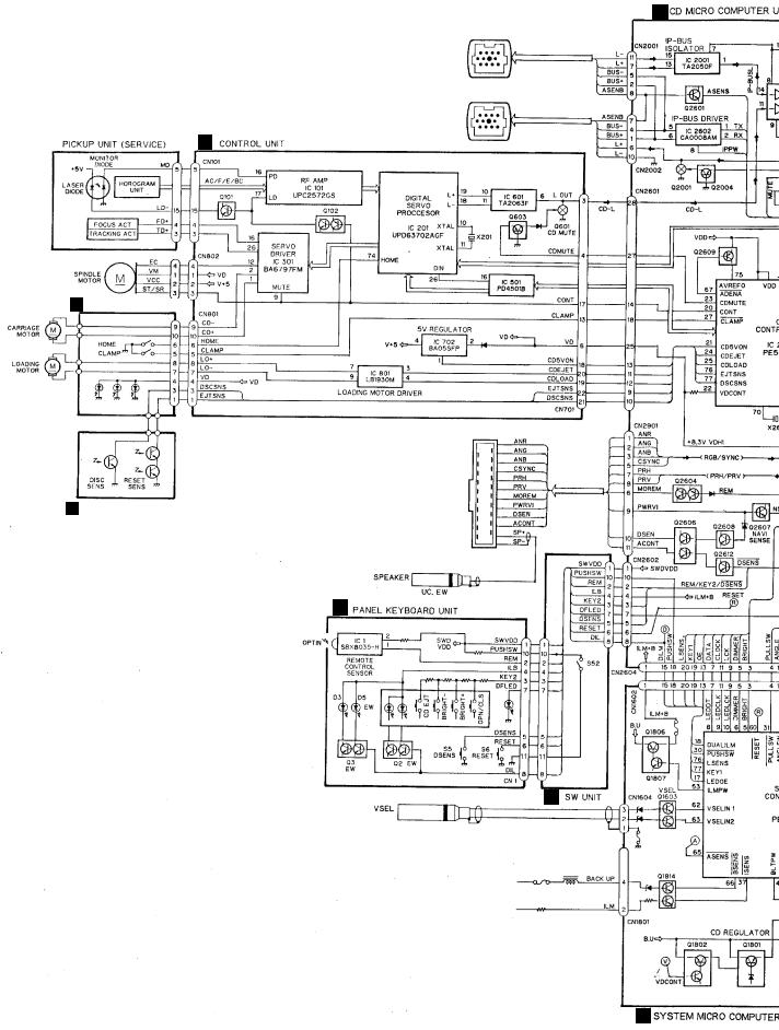
3. BLOCK DIAGRAM AND SCHEMATIC DIAGRAM
3.1 BLOCK DIAGRAM
B
G
H MECHANISM FPC UNIT
I PHOTO FPC UNIT
E
J
A
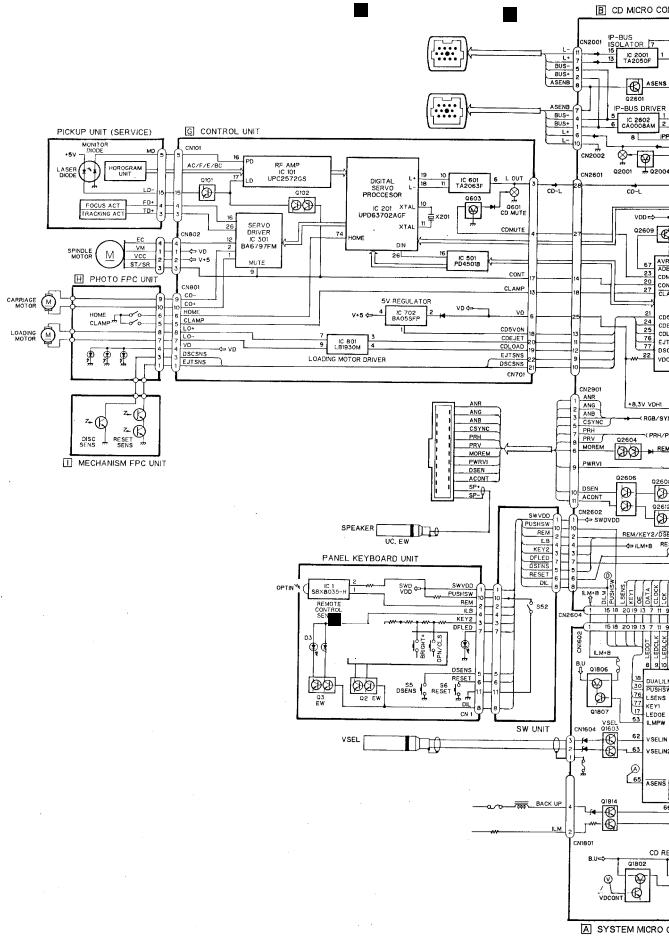
AVX-P7000CD
C |
D |
|
F
13
1 |
|
2 |
|
3 |
|
4 |
|
|
|
AVX-P7000CD
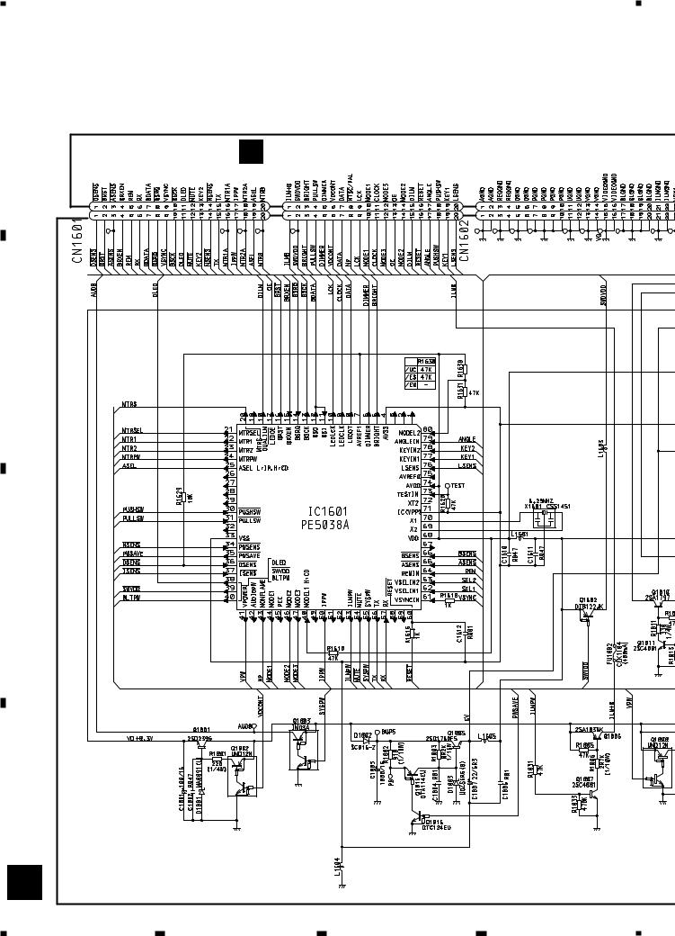
3.2 SYSTEM MICRO COMPUTER UNIT
Note: When ordering service parts, be sure to refer to “EXPLODED VIEWS AND PARTS LIST” or “ELECTRICAL
PARTS LIST”.
A
B CD MICRO COMPUTER UNIT
CN2603 |
CN2604 |
CN2605 |
B
SYSTEM MICRO COMPUTER
C
CD REGULATOR
VDD REGULATOR
D
VIDEO REGU
A
14
1 |
2 |
3 |
4 |
5 |
|
6 |
|
7 |
|
8 |
|
|
|
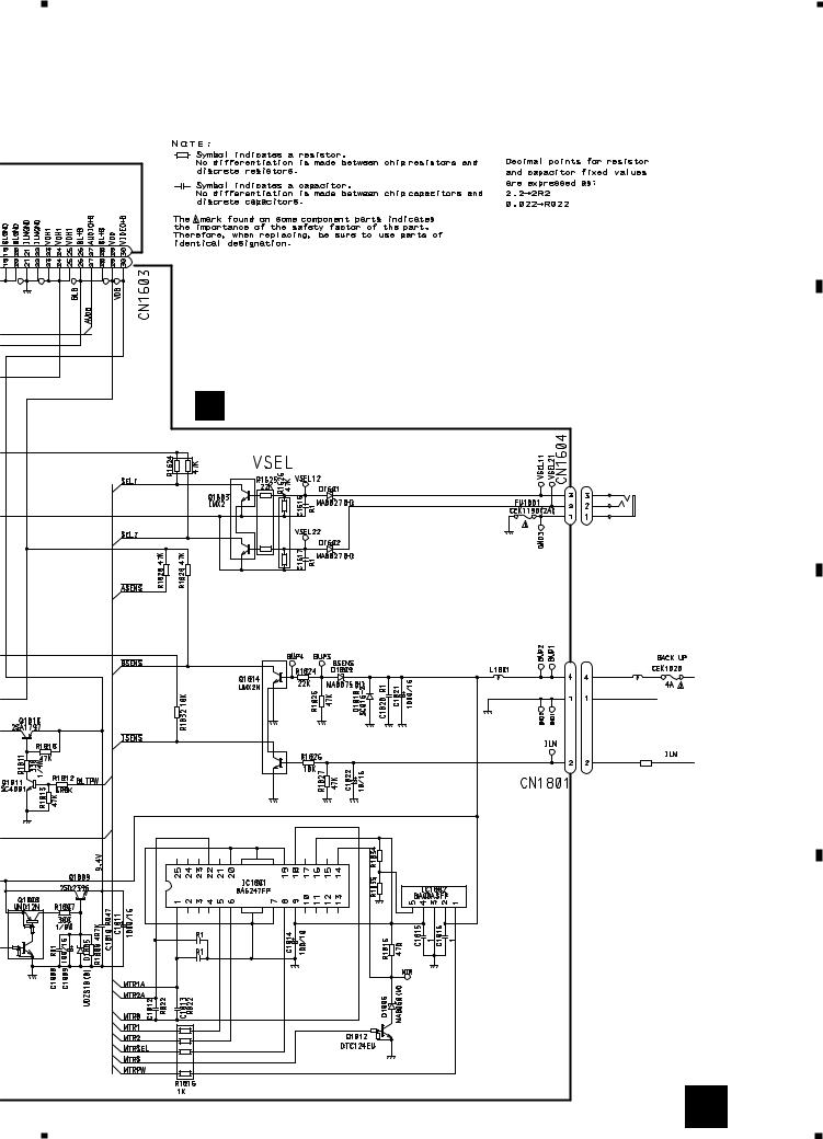
AVX-P7000CD
A
A SYSTEM MICRO COMPUTER UNIT
B
V.SEL
1mH
GND
C
I.SENS
1K(1/2W)
2R2K 16K
C1818
C1817
D
EO REGULATOR
MOTOR DRIVER
A 15
5 |
|
6 |
|
7 |
|
8 |
|
|
|
||||
|
|
|

1 |
|
2 |
|
3 |
|
4 |
|
|
|
AVX-P7000CD
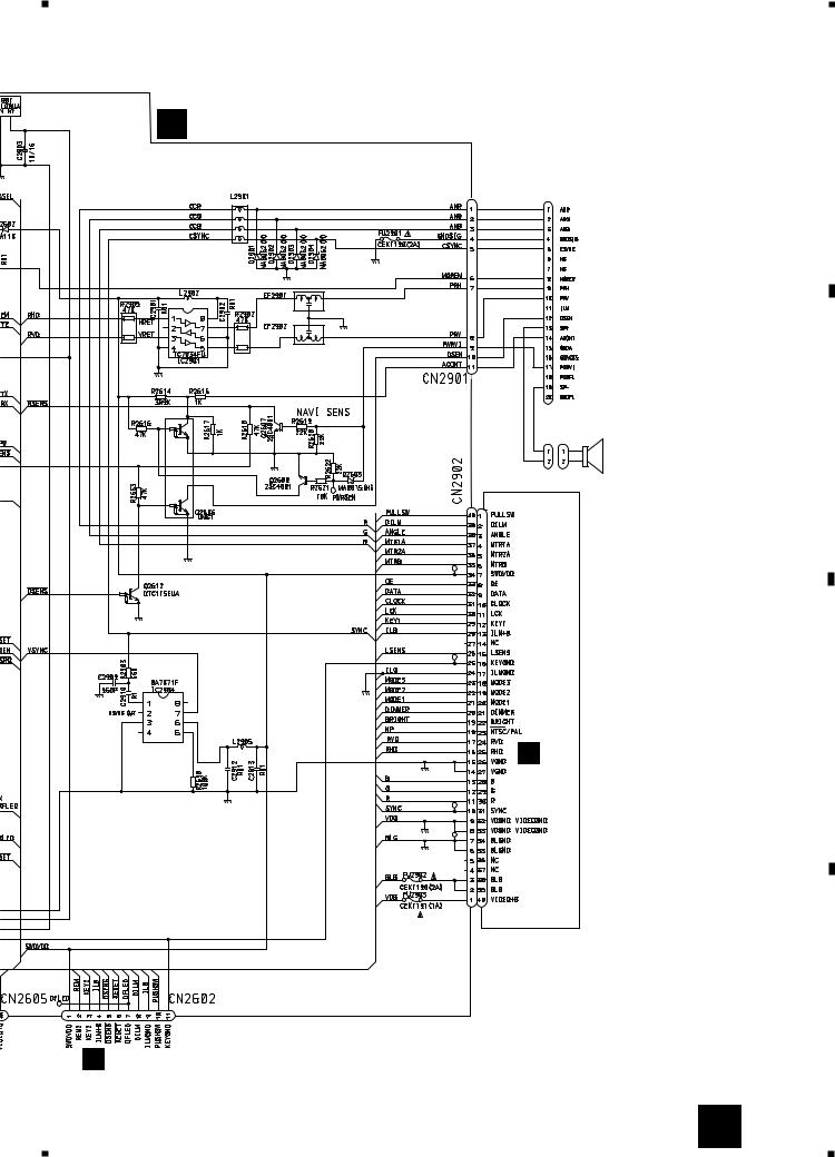
3.3 CD MICRO COMPUTER UNIT
IP-BUS:2.2dBs
A
AUDIO
SELECT
IP-BUS:2.2dBs
S-CD:2.52dBs
B
S-CD:0.22dBs
G
CONTROL
UNIT
CN701
CD MICRO COMPUTER
C
D
A |
|
|
|
A |
|
CN1601 |
A |
CN1602 |
CN1603 |
||
|
|
|
|
|
|
16 B
1 |
2 |
3 |
4 |
5 |
|
6 |
|
7 |
|
8 |
|
|
|||||
|
|
AVX-P7000CD
B CD MICRO COMUTER UNIT
A
UC,EW model |
B |
|
C
|
C |
|
RELAY |
|
UNIT |
SYNCHRONIZING |
CN51 |
SEPARATION |
|
D
J
B 17
5 |
|
6 |
|
7 |
|
8 |
|
|
|
||||
|
|
|
1 |
|
2 |
|
3 |
|
4 |
|
|
|
AVX-P7000CD
3.4 RELAY UNIT AND ENCODER UNIT
M52 |
M51 BACK SENSOR |
ANGLE SENSOR |
|
|
|
SW |
|
FX2484 |
FX2484 |
|
|
|
|
||
A |
|
|
10k(B) |
F
ENCODER UNIT
B
B
CN2902
C
8R2K
D
C RELAY UNIT
18 C F
1 |
2 |
3 |
4 |
T
5 |
|
6 |
|
7 |
|
8 |
|
|
|
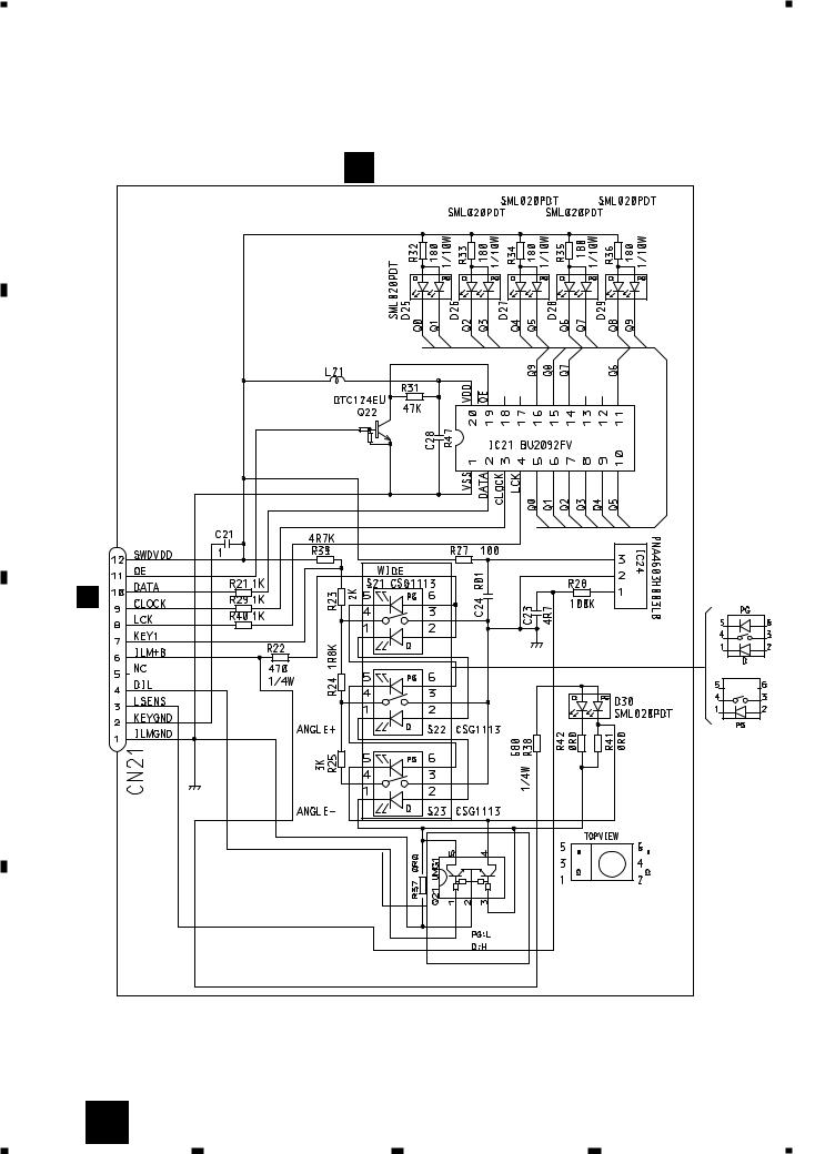
AVX-P7000CD
A
D LCD KEYBOARD UNIT
CN21
B
LCD
MODULE
C
D
C 19
5 |
|
6 |
|
7 |
|
8 |
|
|
|
||||
|
|
|
1 |
|
2 |
|
3 |
|
4 |
|
|
|
AVX-P7000CD
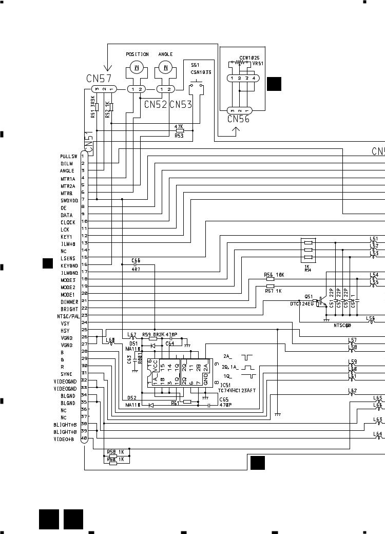
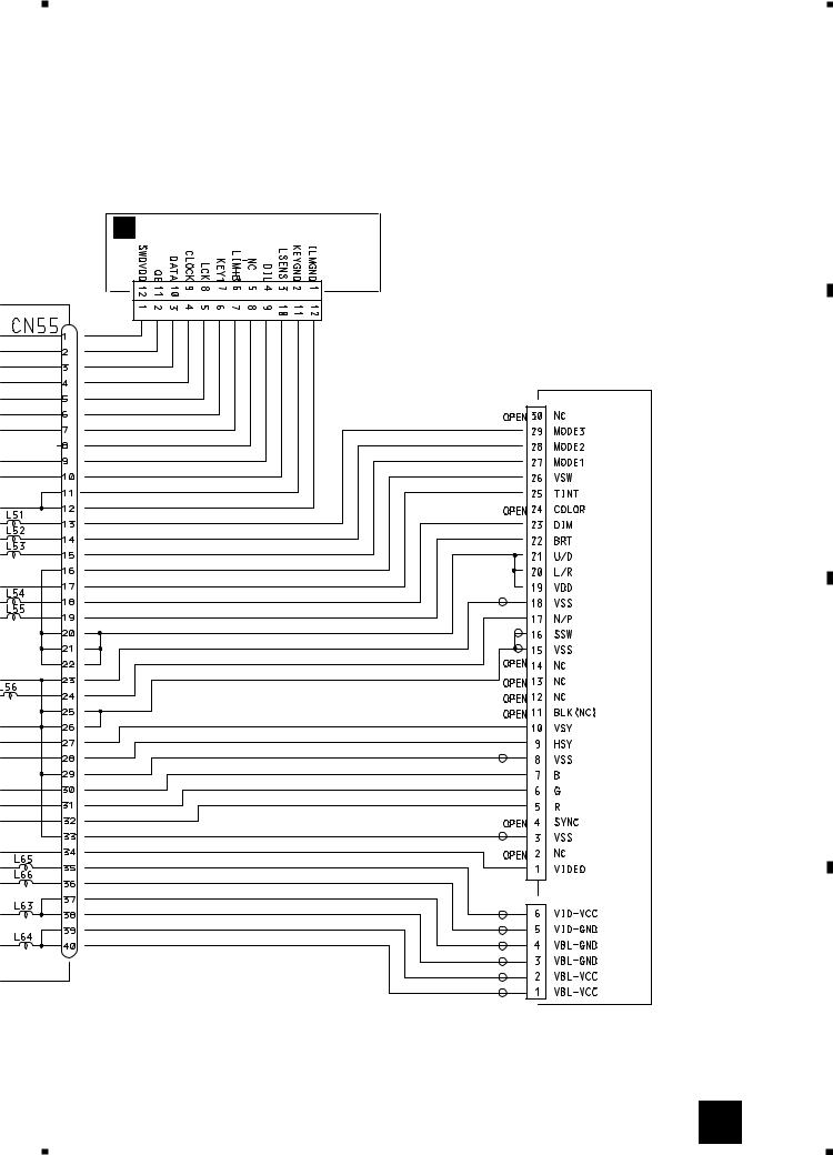
3.5 LCD KEYBOARD UNIT
A
D LCD KEYBOARD UNIT
CINEMA NORMAL FULL ZOOM JUST
B
C
CN55
C
UC,ES model
S21-S23
EW model:CSG1113
UC,ES model:CSG1112
EW model |
UC,ES model |
EW model
D
20 D
1 |
2 |
3 |
4 |
1 |
|
2 |
|
3.6 PANEL KEYBOARD UNIT
EW model
S52 CSN1052
SENSOR SW
UC,ES model
B CN2602
SML210LT |
EW model |
J
SW UNIT
3 |
|
4 |
|
AVX-P7000CD
A
E PANEL KEYBOARD UNIT
B
UC,ES model
C
EW model
D
E J 21
1 |
|
2 |
|
3 |
|
4 |
|
|
|
||||
|
|
|

1 |
|
2 |
|
3 |
|
4 |
|
|
|
AVX-P7000CD
G-a
3.7 CD MECHANISM MODULE(GUIDE PAGE)
A
|
|
|
|
|
|
Large size |
|
|
|
|
|
|
SCH diagram |
|
G-a |
|
|
G-b |
|
|
|
|
|
|
|
||
|
|
|
|
|
|
|
G-a |
G-b |
Guide page |
G-a |
G-b |
Detailed page |
PICKUP UNIT
(SERVICE)
B
H MECHANISM FPC UNIT
C
I PHOTO FPC UNIT
D
22 G H I
1 |
2 |
3 |
4 |
 Loading...