


Installation Manual
Manuel d’installation
NAVIGATION AV SYSTEM
SYSTEME DE NAVIGATION AV
SISTEMA DI NAVIGAZIONE AV
SISTEMA DE NAVEGACIÓN AV
NAVIGATIONS-/AV-SYSTEM
AV NAVIGATIESYSTEEM
AVIC-F550BT
Some wiring and installation are described in the separate installation manual.
Certains câblages et procédés d’installation sont décrits dans le manuel d’installation séparé.
Alcuni dati di cablaggio e installazione sono descritti nel Manuale d’installazione separato.
En el manual de instalación independiente se describe parte del proceso de cableado e instalación.
Gewisse Verkabelungsund Installationsarbeiten sind in der separaten Einbauanleitung beschrieben.
Sommige bedradingsen installatie-informatie staat in de afzonderlijke installatiehandleiding.
Nederlands Deutsch Español Italiano Français English

 Contents
Precautions |
|
|
|
|
|
|
|
||
Your new navigation system and this |
|
||||||||
manual |
3 |
|
|
|
|
|
|
|
|
Important safeguards |
3 |
|
|
|
|
|
|||
Handling the microSD card |
4 |
|
|
|
|||||
Connecting the system |
|
|
|
|
|||||
Precautions before connecting the |
|
|
|||||||
system |
5 |
|
|
|
|
|
|
|
|
Before installing this product |
5 |
|
|
|
|||||
To prevent damage 6 |
|
|
|
|
|
|
|||
– |
Notice for the blue/white lead |
|
6 |
||||||
Parts supplied |
7 |
|
|
|
|
|
|
||
Connecting the system |
8 |
|
|
|
|
||||
Connecting the control line cable |
10 |
||||||||
When connecting to separately sold power |
|||||||||
amp 11 |
|
|
|
|
|
|
|
|
|
When connecting a rear view camera |
12 |
||||||||
When connecting the external video |
|
||||||||
component |
13 |
|
|
|
|
|
|
||
– |
Using an AV input (AUX) |
13 |
|
|
|||||
– |
Using an AV input (USB) |
13 |
|
|
|||||
When connecting the rear display |
14 |
||||||||
– |
When using a rear display connected to |
||||||||
|
rear video output |
14 |
|
|
|
|
|||
Installation |
|
|
|
|
|
|
|
||
Precautions before installation |
15 |
|
|
||||||
To avoid electromagnetic interference |
15 |
||||||||
Before installing 15 |
|
|
|
|
|
|
|||
Installing the navigation system |
16 |
|
|||||||
– |
Installation notes |
16 |
|
|
|
|
|||
– |
Parts supplied |
16 |
|
|
|
|
|
||
– |
Before installing this navigation |
|
|||||||
|
unit |
17 |
|
|
|
|
|
|
|
– |
Installation using the screw holes on |
||||||||
|
the side of the navigation unit |
|
17 |
||||||
Installing the GPS aerial |
18 |
|
|
|
|
||||
– |
Installation notes |
18 |
|
|
|
|
|||
– |
Parts supplied |
18 |
|
|
|
|
|
||
– |
When installing the aerial inside the |
|
|
vehicle (on the dashboard or rear |
|
|
shelf) 19 |
|
Installing the microphone |
20 |
|
– |
Parts supplied 20 |
|
– |
Mounting on the sun visor 20 |
|
– |
Installation on the steering column 21 |
|
After installation |
|
|
After installing this product |
22 |
|
 2
2 Engb
Engb
 Precautions
Your new navigation |
Important safeguards |
|
system and this manual |
WARNING |
|
! The navigation features of this product |
||
Pioneer does not recommend that you install |
||
(and the rear view camera option if pur- |
your navigation system yourself. This pro- |
|
chased) are intended solely to aid you in |
duct is designed for professional installation |
|
the operation of your vehicle. It is not a sub- |
only. We recommend that only authorised |
|
stitute for your attentiveness, judgement |
Pioneer service personnel, who have special |
|
and care when driving. |
training and experience in mobile electro- |
|
! Never use this navigation system to route |
nics, set up and install this product. NEVER |
|
to hospitals, police stations, or similar facil- |
SERVICE THIS PRODUCT YOURSELF. In- |
|
ities in an emergency. Please call the ap- |
stalling or servicing this product and its con- |
|
propriate emergency number. |
necting cables may expose you to the risk of |
|
! Do not operate this navigation system (or |
electric shock or other hazards, and can |
|
the rear view camera option if purchased) if |
cause damage to the navigation system that |
|
doing so will divert your attention in any |
is not covered by warranty. |
|
way from the safe operation of your vehicle. |
|
|
Always observe safe driving rules and fol- |
! Read this manual fully and carefully before |
|
low all existing traffic regulations. If you ex- |
installing your navigation system. |
|
perience difficulty in operating the system |
! Keep this manual handy for future refer- |
|
or reading the display, park your vehicle in |
ence. |
|
a safe location and apply the handbrake be- |
! Pay close attention to all warnings in this |
|
fore making the necessary adjustments. |
manual and follow the instructions care- |
|
! This manual explains how to install this na- |
fully. |
|
vigation system in your vehicle. Operation |
! This navigation system may in certain cir- |
|
of this navigation system is explained in |
cumstances display inaccurate position of |
|
the separate manuals for the navigation |
your vehicle, the distance of objects shown |
|
system. |
on the screen, and compass directions. In |
|
! Do not install this product where it may (i) |
addition, the system has certain limita- |
|
obstruct the driver’s vision, (ii) impair the |
tions, including the inability to identify one- |
|
performance of any of the vehicle’s operat- |
way streets, temporary traffic restrictions |
|
ing systems of safety features, including |
and potentially unsafe driving areas. Please |
|
airbags, hazard lamp buttons, or (iii) impair |
exercise your own judgement in the light of |
|
the driver’s ability to safely operate the vehi- |
actual driving conditions. |
|
cle. In some cases, it may not be possible |
! As with any accessory in your vehicle’s in- |
|
to install this product because of the vehi- |
terior, the navigation system should not di- |
|
cle type or the shape of the vehicle inter- |
vert your attention from the safe operation |
|
ior. |
of your vehicle as it may result in serious |
|
|
injury or death. If you experience difficulty |
|
|
in operating the system or reading the dis- |
|
|
play, please make adjustments while safely |
|
|
parked. |
|
|
! Please remember to wear your seat belt at |
|
|
all times while operating your vehicle. If |
|
|
you are in an accident, your injuries can be |
|
|
considerably more severe if your seat belt |
|
|
is not properly fastened. |
Section
01
English
Engb  3
3
Section
01  Precautions
!Certain country and government laws may prohibit or restrict the placement and use of this system in your vehicle. Please comply with all applicable laws and regulations
regarding the use, installation and operation of your navigation system.
Handling the microSD card
A microSD card is installed in the SD card slot of this navigation system. Without the microSD card, the navigation system will not operate properly.
Do not remove the microSD card from the SD card slot except when performing software updates.
= For details, refer to Operation Manual.
 4
4 Engb
Engb
 Connecting the system
Precautions before |
damaged, resulting in a short circuit or |
|
connecting the system |
malfunction and permanent damage to |
|
the product. |
||
|
||
WARNING |
! Do not cut the GPS aerial cable to shorten |
|
it or use an extension to make it longer. |
||
Do not take any steps to tamper with or dis- |
||
Altering the aerial cable could result in a |
||
able the handbrake interlock system which |
||
short circuit or malfunction. |
||
is in place for your protection. Tampering |
||
! Do not shorten any leads. If you do, the |
||
with or disabling the handbrake interlock |
||
protection circuit (fuse holder, fuse resis- |
||
system could result in serious injury or |
||
tor or filter, etc.) may fail to work properly. |
||
death. |
||
! Never feed power to other electronic pro- |
||
|
||
CAUTION |
ducts by cutting the insulation of the |
|
power supply lead of the navigation sys- |
||
! If you decide to perform the installation |
tem and tapping into the lead. The current |
|
yourself, and have special training and ex- |
capacity of the lead will be exceeded, |
|
perience in the mobile electronics instal- |
causing overheating. |
|
lations, please carefully follow all of the |
|
|
steps in the installation manual. |
|
|
! Secure all wiring with cable clamps or |
Before installing this product |
|
electrical tape. Do not allow any bare wir- |
||
! Use this unit with a 12-volt battery and ne- |
||
ing to remain exposed. |
||
! Do not directly connect the yellow lead of |
gative earthing only. Failure to do so may |
|
this product to the vehicle battery. If the |
result in a fire or malfunction. |
|
lead is directly connected to the battery, |
! To avoid shorts in the electrical system, be |
|
engine vibration may eventually cause |
sure to disconnect the (–) battery cable be- |
|
the insulation to fail at the point where |
fore installation. |
|
the wire passes from the passenger com- |
|
|
partment into the engine compartment. If |
|
|
the yellow lead’s insulation tears as a re- |
|
|
sult of contact with metal parts, short-cir- |
|
|
cuiting can occur, resulting in |
|
|
considerable danger. |
|
!It is extremely dangerous to allow cables to become wound around the steering column or gearstick. Be sure to install this product, its cables, and wiring away in such so that they will not obstruct or hinder driving.
!Make sure that the cables and wires will not interfere with or become caught in any of the vehicle’s moving parts, especially the steering wheel, gearstick, handbrake, sliding seat tracks, doors, or any of the vehicle’s controls.
!Do not route wires where they will be exposed to high temperatures. If the insulation heats up, wires may become
Section
02
English
Engb  5
5
Section
02  Connecting the system
To prevent damage
 WARNING
!Use speakers over 50 W (output value) and between 4 W to 8 W (impedance value). Do not use 1 W to 3 W speakers for this
unit.
!The black lead is earth. Please earth this lead separately from the earth of high-cur- rent products such as power amps. Do not earth more than one product together with the earth from another product. For example, you must separately earth any amp unit away from the earth of this navigation system. Connecting earths together can cause a fire and/or damage the products if their earths became detached.
!When replacing the fuse, be sure to only use a fuse of the rating prescribed on this product.
!When disconnecting a connector, pull the connector itself. Do not pull the lead, as you may pull it out of the connector.
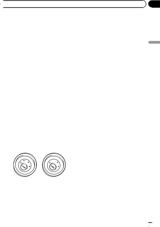
!This product cannot be installed in a vehicle without ACC (accessory) position on the ignition switch.
|
CC |
|
|
|
|
F |
A |
O |
|
F |
O |
|
|
||||
|
N |
N |
|||
F |
|
|
|
F |
|
O |
|
|
|
O |
|
|
|
|
S |
|
S |
|
|
|
T |
|
T |
|
|
|
A |
|
A |
|
|
T |
R |
|
T |
ACC position |
No ACC position |
||||
!To avoid short-circuiting, cover the disconnected lead with insulating tape. It is especially important to insulate all unused speaker leads, which if left uncovered may cause a short circuit.
!Attach the connectors of the same colour to the corresponding coloured port, i.e., blue connector to the blue port, black to black, etc.
!Refer to the owner’s manual for details on connecting the power amp and other units,
then make connections accordingly.
!Since a unique BPTL circuit is employed, do not directly earth the * side of the speaker lead or connect the * side of another side of the speaker lead together. Be sure to connect the * side of the speaker lead to the * side of the speaker lead on this navigation system.
!If the RCA pin jack on this product will not be used, do not remove the caps attached to the end of the connector.
Notice for the blue/white lead
!When the ignition switch is turned on (ACC ON), a control signal is output through the blue/white lead. Connect to an external power amp’s system remote control terminal, the auto-aerial relay control terminal, or the aerial booster power control terminal (max. 300 mA 12 V DC). The control signal is output through the blue/white lead, even if the audio source is switched off.
!Be sure not to use this lead as the power supply lead for the external power amps. Such connection could cause excessive current drain and malfunction.
!Be sure not to use this lead as the power supply lead for the auto-aerial or aerial
booster. Such connection could cause excessive current drain and malfunction.
 6
6 Engb
Engb
 Connecting the system
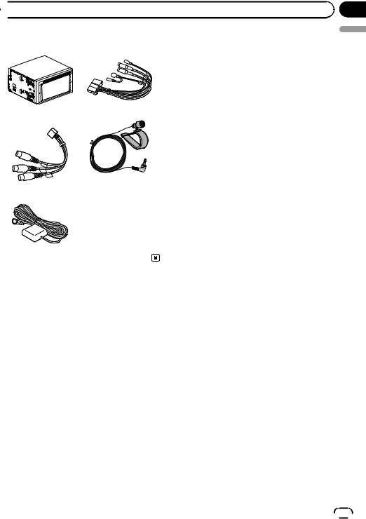
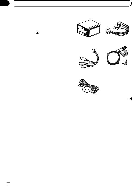
Parts supplied
The navigation unit |
Control line cable |
AV connector cord |
Microphone |
GPS aerial |
|
Section
02
English
Engb  7
7
Section
02  Connecting the system
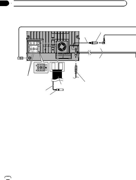
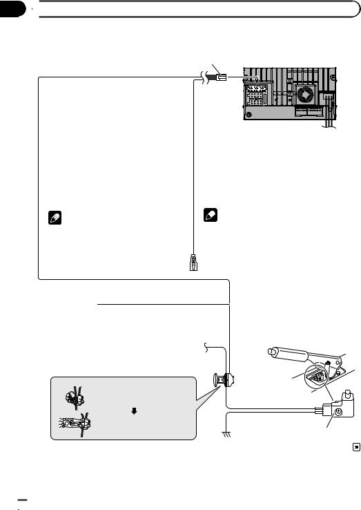
Connecting the system
The navigation unit |
Microphone jack (MIC) |
|
|
|
12 cm |
12 cm
12 cm
|
(*1) |
Fuse (15 A) |
|
Power cord |
|
For connection, refer to the |
|
wiring and installation manual |
Vehicle aerial |
separately supplied. |
Control line cable |
25 cm |
|
Wired remote input (SWC)
Please refer to the instruction manual for the Hard-wired remote control adapter.
(*1)
Make sure that the three yellow, green and blue connectors are attached before connecting the system.
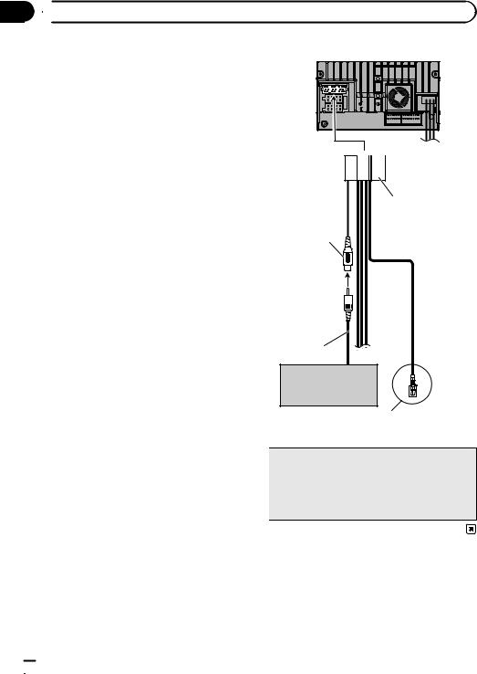
(*2)
Connect either the USB interface cable for iPod or an appropriate USB storage device.
(*3)
When connecting your iPod, both connections are necessary.
(*4)
For details concerning operations and compatibility, refer to Operation Manual.
 8
8 Engb
Engb
 Connecting the system
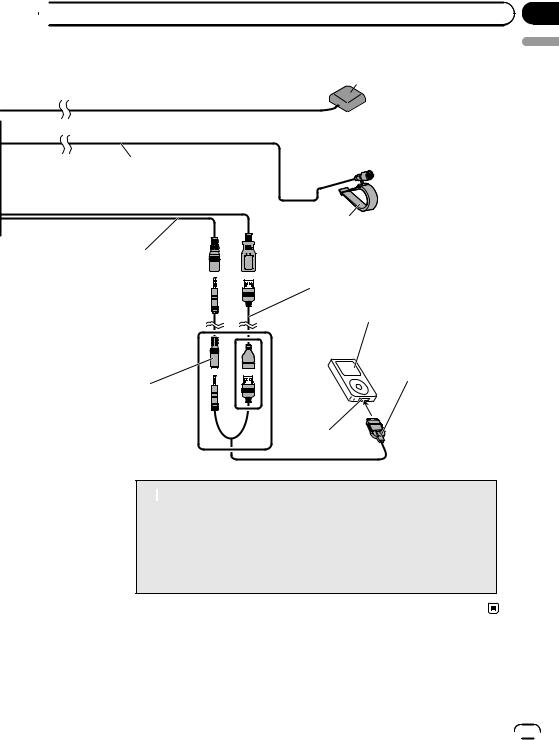
 GPS aerial
 3 m
3 m
4 m
Microphone
AV cable (iPod/AV IN)
AV cable
(sold separately)
USB cable (sold separately)
iPod or iPhone (*4)
(*3)
USB interface cable for iPod (sold separately)
(*2)
Dock Connector port
 WARNING
·To avoid the risk of accident and the potential violation of applicable laws, this product should never be used while the vehicle is being driven except for navigation purposes. And, also rear displays should not be in a location where it is a visible distraction to the driver.
·In some countries, the viewing of images on a display inside a vehicle even by persons other than the driver may be illegal. Where such regulations apply they must be obeyed and this product’s video source should not be used.
Section
02
English
Engb  9
9
Section
02  Connecting the system
Connecting the control line cable
Control line cable
The navigation unit
 Green/white (BRAKE)
Used to detect the ON/OFF status of the handbrake. This lead must be connected to the power supply side of the handbrake switch.
If this connection is made incorrectly or omitted, certain functions of this product will be unusable.
 Pink (REVERSE)
This is connected so that the this product can detect whether the vehicle is moving forwards or backwards. Connect the pink lead to the lead whose voltage changes when the reverse gear is engaged. Unless connected, the sensor may not detect your vehicle travelling forward/backward properly, and thus the position of your vehicle detected by the sensor may be misaligned from the actual position.
|
|
Note |
Note |
|
|
|
|
|
The position of the handbrake switch vary |
|
When you use a rear view camera, please make |
|
sure to connect this lead. Otherwise you cannot |
|
depending on the vehicle model. For details, |
|
|
|
switch to the rear view camera picture. |
|
consult your authorised Pioneer dealer or an |
|
|
|
|
|
installation professional. |
|
|
|
|
|
 WARNING
GREEN/WHITE LEAD AT POWER CONNECTOR IS
DESIGNED TO DETECT PARKED STATUS AND MUST
BE CONNECTED TO THE POWER SUPPLY SIDE OF THE
HANDBRAKE SWITCH. IMPROPER CONNECTION OR
USE OF THIS LEAD MAY VIOLATE APPLICABLE LAW
AND MAY RESULT IN SERIOUS INJURY OR DAMAGE.
Connection method |
|
Clamp the lead of the power supply |
Power supply side |
side of the handbrake switch. |
|
Clamp firmly with needle-nosed |
Earth side |
|
|
pliers. |
Handbrake switch |
|
 10
10 Engb
Engb
 Connecting the system
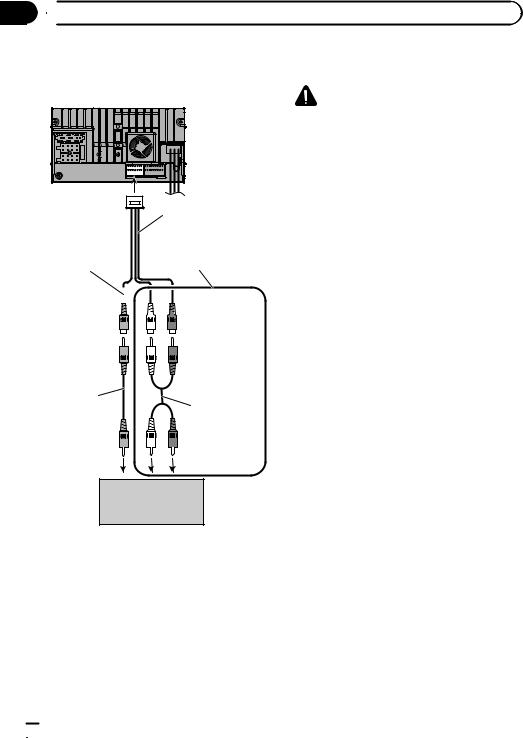
When connecting to separately sold power amp
The navigation unit
Section
02
English
|
Red |
White |
AV connector cord |
(FULL/SW) |
(FULL/SW) |
|
Right |
Left |
Control line cable
RCA cables (sold separately)
Blue/white (P.CONT) |
|
|
|
Power amp |
To system control terminal of |
|
|
|
|
|
|
|
(sold separately) |
|
the power amp |
|
|
|
|
|
|
|
|
|
(max. 300 mA 12 V DC). |
|
|
|
|
|
|
|
System remote control |
|
Connect to the power supply line |
|
|
|
|
terminal (sold separately) equivalent to |
Rear speaker or |
Rear speaker or |
||
P.CONT. |
Subwoofer |
|
|
Subwoofer |
|
|
|
||
 Note
Note
You can change the RCA output of the subwoofer depending on your subwoofer system. (Refer to Operation Manual.)
Engb  11
11
Section
02  Connecting the system
When connecting a rear |
The navigation unit |
view camera |
|
When this product is used with a rear view camera, it is possible to automatically switch from the video to rear view image when the gearstick is moved to REVERSE (R). RearView mode also allows you to check what is behind you while driving.
p For details, refer to Operation Manual.
 WARNING
USE INPUT ONLY FOR REVERSE OR MIRROR IMAGE REAR VIEW CAMERA. OTHER USE MAY RESULT IN INJURY OR DAMAGE.
 CAUTION
!The screen image may appear reversed.
!The rear view camera is used as an aid to keep an eye on trailers, or backing into a tight parking spot. Do not use this function for entertainment purposes.
!Objects in rear view may appear closer or more distant than in reality.
!Please note that the image area shown by the rear view camera may differ slightly when fullscreen images are displayed when backing and when checking the rear of the vehicle while moving forward.
Control line cable
Yellow
(CAMERA VIDEO)
 Pink
Pink
(REVERSE)
RCA cable
Rear view camera (e.g. ND-BC6) (sold separately)
For more details about the wiring, refer to Connecting the control line cable on page 10.
 Note
Note
Connect the navigation system to the rear view camera only. Do not connect to any other equipment.
 12
12 Engb
Engb

 Connecting the system
When connecting the |
CAUTION |
|
external video component |
||
Be sure to use a mini-jack AV cable (CD-RM10) |
||
Using an AV input (AUX) |
(sold separately) for wiring. If you use other |
|
cables, the wiring position might differ resulting |
||
|
||
The navigation unit |
in disturbed images and sounds. |
Section
02
English
|
OK |
|
|
|
|
|
|
|
|
|
L : Left audio (White) |
|
|
|
L |
L |
R : Right audio (Red) |
|
V |
G |
R |
R G V |
V : Video (Yellow) |
|
G : Earth |
||||
AV cable |
|
|
|
|
|
(iPod/AV IN) |
|
|
|
|
|
|
Using an AV input (USB) |
||||
AV cable |
The navigation unit |
|
|||
(sold separately) |
|
||||
|
|
|
|
|
|
Mini-jack AV cable |
|
|
|
|
|
(CD-RM10) |
|
|
|
|
|
(sold separately) |
|
|
|
|
|
Yellow 

White, Red
RCA cables (sold separately)
USB cable  (sold separately)
To video output |
To audio outputs |
External video
component
(sold separately)
USB storage device
Engb  13
13
Section
02  Connecting the system
When connecting the rear |
When using a rear display |
display |
connected to rear video output |
The navigation unit |
WARNING |
AV connector cord |
NEVER install the rear display in a location that enables the driver to watch the video source while driving.
This navigation system’s rear video output is for connection of a display to enable passengers in the rear seats to watch the video source.
 When connecting a rear display with an audio RCA
Yellow input

 White, Red
RCA cable |
RCA cable |
(sold separately) |
(sold separately) |
To video input |
To audio inputs |
Rear display with |
|
RCA input jacks |
|
 14
14 Engb
Engb

 Installation
Precautions before |
! Do not install this navigation system |
|
installation |
where it may (i) obstruct the driver’s vi- |
|
sion, (ii) impair the performance of any of |
||
|
||
CAUTION |
the vehicle’s operating systems or safety |
|
features, including airbags, hazard lamp |
||
! Never install this product in places where, |
||
buttons or (iii) impair the driver’s ability |
||
or in a manner that: |
||
to safely operate the vehicle. |
||
— Could injure the driver or passengers if |
||
! Install the navigation system between the |
||
the vehicle stops suddenly. |
||
driver’s seat and front passenger seat so |
||
— May interfere with the driver’s opera- |
||
that it will not be hit by the driver or pas- |
||
tion of the vehicle, such as on the floor |
||
senger if the vehicle stops quickly. |
||
in front of the driver’s seat, or close to |
||
! Never install the navigation system in |
||
the steering wheel or gearstick. |
||
front of or next to the place in the dash- |
||
! Make sure there is nothing behind the |
||
board, door, or pillar from which one of |
||
dashboard or panelling when drilling |
||
your vehicle’s airbags would deploy. |
||
holes in them. Be careful not to damage |
||
Please refer to your vehicle’s owner’s |
||
fuel lines, brake lines, electronic compo- |
||
manual for reference to the deployment |
||
nents, communication wires or power |
||
area of the frontal airbags. |
||
cables. |
||
! Failure to follow all of these precautions |
||
! When using screws, do not allow them to |
||
may result in serious injury or death. |
||
come into contact with any electrical lead. |
||
|
||
Vibration may damage wires or insulation, |
|
|
leading to a short circuit or other damage |
To avoid electromagnetic |
|
to the vehicle. |
||
! To ensure proper installation, be sure to |
interference |
|
use the supplied parts in the manner spe- |
In order to prevent interference, set the follow- |
|
cified. If any parts are not supplied with |
||
ing items as far as possible from this naviga- |
||
this product, use compatible parts in the |
||
tion system, other cables or leads: |
||
manner specified after you have the parts’ |
||
! FM, MW/LW aerial and its lead |
||
compatibility checked by your dealer. If |
||
! GPS aerial and its lead |
||
parts other than supplied or compatible |
||
In addition, you should lay or route each aerial |
||
ones are used, they may damage internal |
||
lead as far as possible from other aerial leads. |
||
parts of this product or they may work |
||
Do not bind, lay or route them together, or |
||
loose and the product may become de- |
||
cross them. Electromagnetic noise will in- |
||
tached. |
||
crease the potential for errors in the vehicle’s |
||
! It is extremely dangerous to allow cables |
||
location display. |
||
to become wound around the steering col- |
||
|
||
umn or gearstick. Be sure to install this |
|
|
product, its cables, and wiring away in |
Before installing |
|
such so that they will not obstruct or hin- |
||
der driving. |
! Consult with your nearest dealer if installa- |
|
! Make sure that leads cannot get caught in |
tion requires drilling holes or other modifi- |
|
a door or the sliding mechanism of a seat, |
cations of the vehicle. |
|
resulting in a short circuit. |
! Before making a final installation of this |
|
! Please confirm the proper function of |
product, temporarily connect the wiring to |
|
your vehicle’s other equipment after in- |
confirm that the connections are correct |
|
stallation of the navigation system. |
and the system works properly. |
Section
03
English
Engb  15
15
Section
03  Installation
Installing the navigation |
! When installing, to ensure proper heat dis- |
||||
system |
|
persal when using this unit, make sure you |
|||
|
leave ample space behind the rear panel |
||||
|
|
||||
Installation notes |
|
and wrap any loose cables so they are not |
|||
! Do not install the navigation system in |
blocking the vents. |
|
|||
|
|
|
|||
places subject to high temperatures or hu- |
|
|
|
||
midity, such as: |
|
|
|
|
|
— Places close to a heater, vent or air con- |
|
|
|
||
ditioner. |
|
Leave ample |
5 cm |
|
|
— Places exposed to direct sunlight, such |
space |
|
|||
|
|
||||
as on top of the dashboard. |
|
5 cm |
|
||
— Places that may be exposed to rain, |
|
|
|||
|
|
|
|||
such as close to the door or on the vehi- |
|
|
|
||
cle’s floor. |
|
|
|
|
|
! Install this navigation system in an area |
! The cords must not cover the area shown |
||||
strong enough to bear its weight. Choose a |
|||||
in the figure below. This is necessary to |
|||||
position where this navigation system can |
|||||
allow the amps and navigation mechanism |
|||||
be firmly installed, and install it securely. If |
|||||
to dissipate heat. |
|
||||
this navigation system is not securely in- |
|
||||
|
|
|
|||
stalled, the current location of the vehicle |
|
|
|
||
cannot be displayed correctly. |
|
|
|
|
|
! Install the navigation unit horizontally on a |
|
|
|
||
surface within 0 to 30 degrees tolerance |
|
|
|
||
(within 5 degrees to the left or right). Impro- |
|
|
|
||
per installation of the unit with the surface |
|
|
|
||
tilted more than these tolerances increases |
|
|
|
||
the potential for errors in the vehicle’s loca- |
|
|
|
||
tion display, and might otherwise cause re- |
|
|
Do not cover this area. |
||
duced display performance. |
|
! The semiconductor laser will be damaged |
|||
|
|
if it overheats, so don’t install the naviga- |
|||
|
|
tion unit anywhere hot — for instance, near |
|||
|
|
a heater outlet. |
|
|
|
30° |
|
Parts supplied |
|
||
|
|
|
|
||
5° |
5° |
|
|
|
|
|
|
The navigation unit |
Tape |
||
|
|
|
|
(2 pcs.) |
|
 16
16 Engb
Engb
|
Section |
Installation |
03 |
Truss head screw |
Flush surface screw |
(5 mm × 6 mm) |
(5 mm × 7 mm) |
(6 pcs.) |
(6 pcs.) |
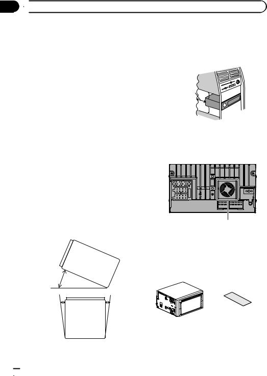
Before installing this navigation unit
 CAUTION
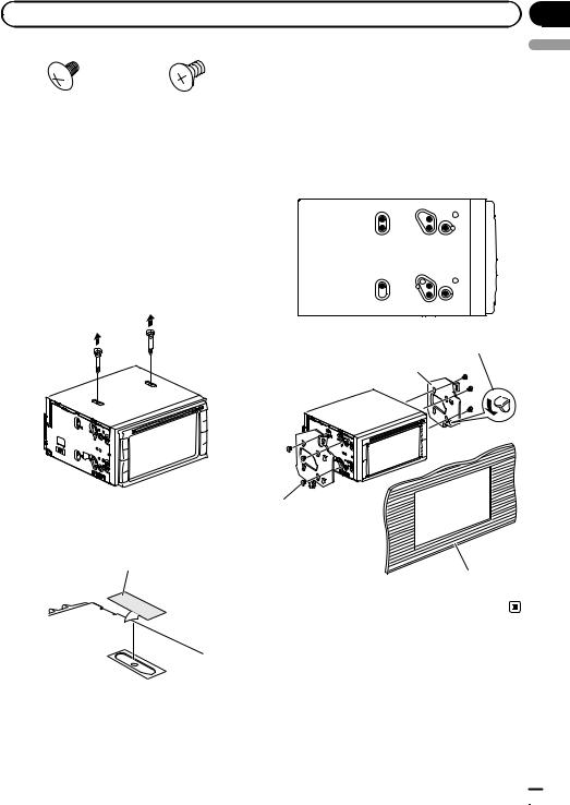
The disc player will not operate properly if you do not remove the two bolts from the navigation unit. Using the disc player without removing the bolts may cause a malfunction.
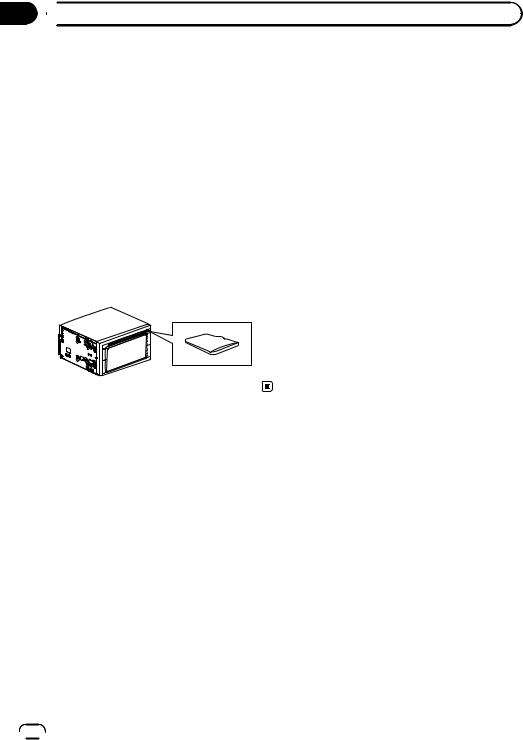
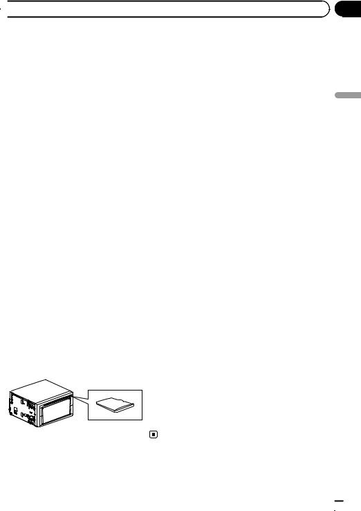
1 Remove the two shipping bolts.
Installation using the screw holes on the side of the navigation unit
% Fastening the navigation unit to the factory radio-mounting bracket.
Position the navigation unit so that its screw holes are aligned with the screw holes of the bracket, and tighten the screws at three locations on each side.
English
If the pawl interferes with installation, you may bend it down out of the way.
Factory radio-mounting bracket
2 Seal the two screw holes with the pieces of tape supplied with the navigation unit.
Tape
Truss head screw or flush surface screw
Be sure to use the |
|
screws supplied with |
|
this navigation |
|
system. |
Dashboard or console |
Engb  17
17
Section
03  Installation
Installing the GPS aerial
 CAUTION
Do not cut the GPS aerial lead to shorten it or use an extension to make it longer. Altering the aerial cable could result in a short circuit or malfunction and permanent damage to the navigation system.
Installation notes
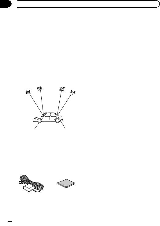
!The aerial should be installed on a level surface where radio waves will be blocked as little as possible. Radio waves cannot be received by the aerial if reception from the satellite is blocked.
Dashboard |
|
|
|
Rear shelf |
!Take care not to pull the aerial lead when removing the GPS aerial. The magnet attached to the aerial is very powerful, and the lead may become detached.
!Do not paint the GPS aerial, as this may affect its performance.
Parts supplied
GPS aerial |
Double-sided tape |
 18
18 Engb
Engb
|
Section |
Installation |
03 |
When installing the aerial inside the vehicle (on the dashboard or rear shelf)
 WARNING
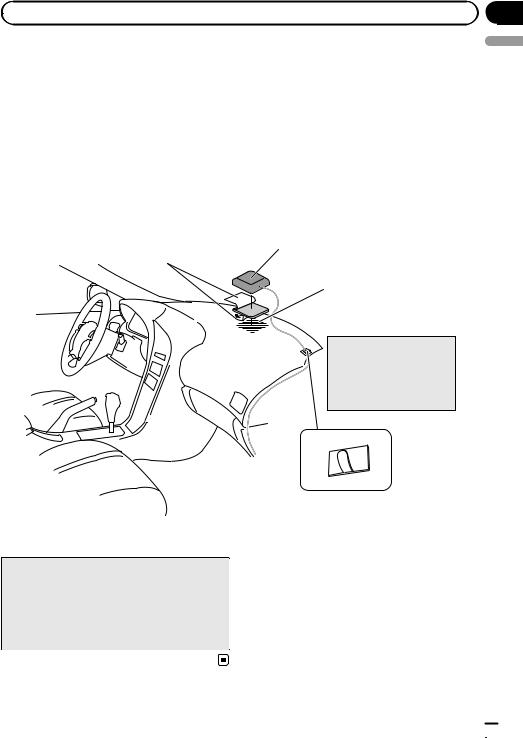
Do not install the GPS aerial over any sensors or vents on the dashboard of the vehicle, as doing so may interfere with the proper functioning of such sensors or vents and may compromise the ability of the double-sided tape under the GPS aerial to properly and securely affix to the dashboard.
Affix the double-sided tape on the surface as level as possible where the GPS aerial faces the window. Place the GPS aerial on the dou- ble-sided tape.
Double-sided tape
Peel off the protective sheet.
 Note
Note
Some models use window glass that does not allow signals from GPS satellites to pass through. On such models, install the GPS aerial on the outside of the vehicle.
GPS aerial
Make sure the surface is free of moisture, dust, grime, oil, etc., before affixing the double-sided tape.
 Note
Note
The double-sided tape contains a strong adhesive which may leave a mark on the surface if it is removed.
Clamps
Use separately sold clamps
to secure the lead where necessary inside the vehicle.
English
Engb  19
19
Section
03  Installation
Installing the microphone |
2 Attach the microphone clip to the sun |
|
! Install the microphone in a place where its |
visor. |
|
Microphone clip |
||
direction and distance from the driver |
||
make it easiest to pick up the driver’s voice. |
|
|
! Make sure to connect the microphone to |
|
|
the navigation system after the system is |
|
|
turned off (ACC OFF). |
|
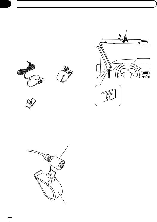
Parts supplied
Microphone |
Microphone clip |
|
Clamps |
|
Use separately sold clamps to secure the lead |
Microphone holder |
where necessary inside the vehicle. |
Mounting on the sun visor
1 Install the microphone to the microphone clip.
Microphone
Install the microphone on the sun visor when it is in the up position. It cannot recognise the driver’s voice if the sun visor is in the down position.
Microphone clip
 20
20 Engb
Engb
 Installation
Installation on the steering column
1 Install the microphone in the microphone holder.
Microphone
Clamps
Use separately sold
clamps to secure the lead where necessary inside the vehicle.
Microphone holder
2 Mount the microphone on the steering column.
Peel off the protective sheet on the rear.
Install the microphone on the steering column, keeping it away from the steering wheel.
Section
03
English
Engb  21
21
Section
04  After installation
After installing this product
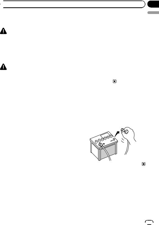
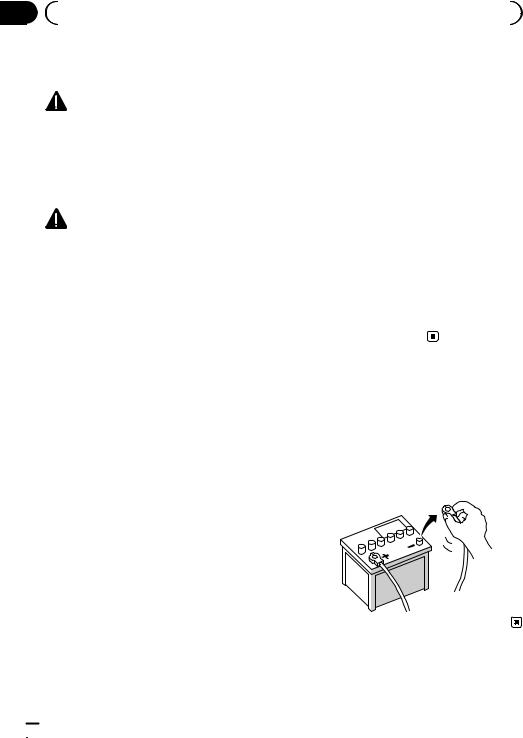
1Reconnect the negative (–) terminal of the vehicle’s battery.
First, double-check that all connections are correct and that this product is installed correctly. Reassemble all vehicle components that you previously removed. Then reconnect the negative (–) cable to the negative (–) terminal of the battery.
2Start the engine.
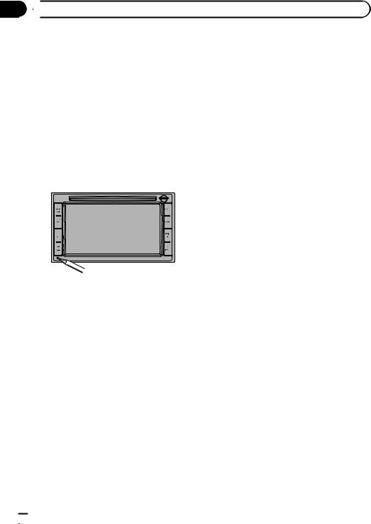
3Press the reset button.
Press the reset button on this product with a pointed object such as the tip of a pen.
4Make the following settings.
=For details concerning operations, refer to
Operation Manual.
1Set the language.
2Drive an unobstructed road until the GPS starts receiving the signal normally.
3Make some necessary adjustments.
!Setting the time
!Setting the units and the date format, etc.
!Change other settings as you prefer
 Note
Note
After installing this product, be sure to check at a safe place that the vehicle is performing normally.
 22
22 Engb
Engb

 Sommaire
 Précautions
Votre nouveau système de navigation et ce
manuel 24 |
|
Importantes mesures de sécurité |
24 |
Manipulation de la carte microSD |
25 |
 Branchement du système
Précautions à prendre avant de brancher le système 26
Avant d’installer ce produit 26 Pour éviter toute détérioration 27
–Remarque concernant le fil bleu/ blanc 27
Pièces fournies |
28 |
|
|
|
||
Branchement du système 30 |
|
|
||||
Branchement du câble de ligne de |
|
|||||
contrôle |
32 |
|
|
|
|
|
Branchement d’un amplificateur de |
|
|||||
puissance vendu séparément |
33 |
|
||||
Branchement d’une caméra de |
|
|
||||
rétrovisée |
34 |
|
|
|
|
|
Branchement d’un élément vidéo |
|
|
||||
externe 35 |
|
|
|
|
||
– |
Utilisation d’une entrée AV (AUX) |
35 |
||||
– |
Utilisation d’une entrée AV (USB) |
35 |
||||
Branchement de l’écran arrière |
36 |
|
||||
– Utilisation d’un écran arrière raccordé |
||||||
|
à la sortie vidéo arrière 36 |
|
|
|||
Installation |
|
|
|
|
|
|
Précautions à prendre avant |
|
|
||||
l’installation |
37 |
|
|
|
||
Pour éviter les parasites |
|
|
||||
électromagnétiques |
37 |
|
|
|||
Avant de procéder à l’installation |
38 |
|
||||
Installation du système de navigation |
38 |
|||||
– |
Remarques sur l’installation 38 |
|
||||
– |
Pièces fournies |
39 |
|
|
||
–Avant d’installer cette unité de navigation 39
– |
Installation en utilisant les trous de vis |
|
sur les côtés de cette unité de |
|
navigation 39 |
Installation de l’antenne GPS 40 |
|
– |
Remarques sur l’installation 40 |
– |
Pièces fournies 40 |
–Installation de l’antenne dans le véhicule (sur le tableau de bord ou la
|
lunette arrière) |
41 |
Installation du microphone 42 |
||
– |
Pièces fournies |
42 |
– |
Installation sur le pare-soleil 42 |
|
–Installation sur la colonne de direction 43
 Après l’installation
Après avoir installé ce produit 44
Français
Fr  23
23

Section
01  Précautions
Votre nouveau système de |
Importantes mesures de |
navigation et ce manuel |
sécurité |
!La fonction de navigation de ce produit (et la caméra de rétrovisée en option le cas échéant) est uniquement destinée à vous assister lors de la conduite de votre véhicule. Elle n’autorise en aucun cas un relâchement de votre attention, de votre jugement et de votre vigilance pendant la conduite.
!N’utilisez jamais ce système de navigation en cas d’urgence pour vous rendre à l’hôpital ou dans une station de police. Veuillez le cas échéant appeler le numéro d’urgence du service concerné.
!N’utilisez pas ce système de navigation (ou la caméra de rétrovisée en option le cas échéant) si celui-ci risque d’une façon ou d’une autre de détourner votre attention. Observez toujours les règles de sécurité et respectez toujours les réglementations de la circulation routière en vigueur. Si vous éprouvez des difficultés à utiliser le système ou à lire l’écran, garez votre véhicule en lieu sûr et serrez le frein à main avant d’effectuer les réglages nécessaires.
!Ce manuel explique comment installer le système de navigation dans votre véhicule. Le fonctionnement du système de navigation est expliqué dans les manuels séparés du système de navigation.
!N’installez pas ce produit dans un endroit où il risque (i) d’entraver la visibilité du conducteur, (ii) d’altérer le fonctionnement de certains systèmes de commande des dispositifs de sécurité du véhicule, y compris les airbags ou les touches de feux de détresse, ou (iii) d’empêcher le conducteur de conduire le véhicule en toute sécurité. Dans certains cas, il peut ne pas être possible d’installer ce produit en raison du
type de véhicule ou de la forme de l’intérieur du véhicule. 
 AVERTISSEMENT
Pioneer vous déconseille d’installer vousmême votre système de navigation. Ce produit est conçu pour une installation professionnelle uniquement. Nous vous recommandons de confier l’installation uniquement à un personnel de service Pioneer agréé, qui a été spécialement formé et est expérimenté en matière de systèmes électroniques mobiles, de montage et d’installation de ce type de produit. NE TENTEZ JAMAIS D’EFFECTUER VOUS-MÊME L’ENTRETIEN OU DE DÉPANNER CE SYSTÈME DE NAVIGATION. L’installation ou l’entretien de ce produit et des câbles de raccordement vous expose à des décharges électriques ou autres dangers, et risque de provoquer des détériorations du système de navigation non couvertes par la garantie.
!Lisez attentivement le contenu de ce manuel avant d’installer votre système de navigation.
!Conservez ce manuel à portée de main pour vous y reporter ultérieurement.
!Tenez compte de tous les avertissements formulés dans ce manuel et respectez soigneusement les consignes.
!Dans certaines circonstances, ce système de navigation peut afficher des informations erronées sur la position de votre véhicule, la distance des objets affichés à l’écran et les directions de la boussole. En outre, le système comporte certaines limitations, notamment l’incapacité de signaler les rues à sens unique, les restrictions temporaires à la circulation et les zones où la circulation peut devenir dangereuse. Veuillez vous en remettre à votre bon jugement en fonction des conditions réelles de conduite.
 24
24 Fr
Fr
 Précautions
!Comme tout autre accessoire de l’habitacle, le système de navigation ne doit pas détourner votre attention ni nuire à la sécurité de la conduite sous peine d’entraîner des blessures graves voire mortelles. Si vous éprouvez des difficultés à utiliser le système ou à lire l’écran, effectuez les réglages nécessaires après vous être garé dans un endroit sûr.
!Veillez à toujours porter votre ceinture de sécurité sur la route. En cas d’accident, le port de la ceinture peut réduire considérablement la gravité des blessures.
!Certaines lois nationales ou gouvernementales peuvent interdire ou restreindre l’emplacement et l’utilisation de ce système dans votre véhicule. Veuillez vous conformer à toutes les lois et réglementations en vigueur concernant l’utilisation, l’installa-
tion et le fonctionnement de votre système de navigation.
Manipulation de la carte microSD
Une carte microSD est installé dans la fente de carte SD de ce système de navigation. En l’absence de cette carte, le système de navigation ne pourra pas fonctionner correctement. Ne pas enlever la carte microSD de la fente de carte SD sauf en cas de mises à jour logicielles.
=Pour en savoir plus, consultez le Manuel de fonctionnement.
Section
01
Français
Fr  25
25
Section |
|
|
|
|
|
|
02 |
|
Branchement du système |
|
|
|
|
|
Précautions à prendre avant |
! La trajectoire des fils ne doit pas être ex- |
||||
|
de brancher le système |
posée à des températures élevées. Si l’iso- |
||||
|
lation chauffe, les fils risquent d’être |
|||||
|
|
|
||||
|
|
AVERTISSEMENT |
endommagés, ce qui peut entraîner un |
|||
|
|
court-circuit ou un dysfonctionnement, et |
||||
|
N’essayez pas de modifier ou désactiver le |
|||||
|
endommager de manière irrémédiable le |
|||||
|
système de verrouillage du frein à main, le- |
|||||
|
produit. |
|||||
|
quel est installé pour votre protection. La mo- |
|||||
|
! Ne coupez pas le câble de l’antenne GPS |
|||||
|
dification ou la désactivation du système de |
|||||
|
et n’utilisez pas de rallonge. Une telle mo- |
|||||
|
verrouillage du frein à main peut entraîner |
|||||
|
dification pourrait provoquer un court-cir- |
|||||
|
des blessures graves, voire mortelles. |
|||||
|
cuit ou un dysfonctionnement. |
|||||
|
|
|
||||
|
|
ATTENTION |
! Ne raccourcissez aucun fil conducteur. |
|||
|
|
Vous risqueriez autrement de provoquer |
||||
|
! Si vous décidez de réaliser l’installation |
un dysfonctionnement du circuit de pro- |
||||
|
|
vous-même, et possédez une expérience |
tection (porte-fusibles, résistance de fu- |
|||
|
|
spéciale en installation d’électronique au- |
sible ou filtre, etc.). |
|||
|
|
tomobile, veuillez suivre attentivement |
! N’utilisez jamais le cordon d’alimentation |
|||
|
|
toutes les étapes du manuel d’installa- |
du système d’alimentation pour raccorder |
|||
|
|
tion. |
d’autres appareils électriques. La capacité |
|||
|
! Attachez tous les fils avec des colliers ou |
du cordon serait dépassée, ce qui provo- |
||||
|
|
des serre-câbles. Ne laissez aucun fil à nu. |
querait une surchauffe. |
|||
|
! Ne raccordez pas directement le fil jaune |
|
|
|
|
|
|
|
conducteur de ce produit à la batterie du |
|
|
|
|
|
|
véhicule. Si ce fil conducteur est directe- |
Avant d’installer ce produit |
|||
|
|
ment raccordé à la batterie, les vibrations |
||||
|
|
! Utilisez cet appareil uniquement avec une |
||||
|
|
du moteur peuvent finir par user les câ- |
||||
|
|
bles au niveau de la jonction avec l’habita- |
batterie de 12 V, avec pôle négatif à la |
|||
|
|
cle et provoquer un défaut d’isolation. Si |
masse. Sinon, cela pourrait entraîner un in- |
|||
|
|
l’isolation du fil conducteur jaune se dé- |
cendie ou un mauvais fonctionnement. |
|||
|
|
chire sous l’effet du contact avec des piè- |
! Afin d’éviter tout risque de court-circuit, dé- |
|||
|
|
ces métalliques, il peut en résulter un |
branchez le câble de la borne négative (–) |
|||
|
|
court-circuit extrêmement dangereux. |
de la batterie avant de commencer la pose. |
|||
|
! Il est extrêmement dangereux de laisser |
|
|
|
|
|
|
|
les câbles s’enrouler autour de la colonne |
|
|
|
|
|
|
de direction ou du levier de vitesse. Assu- |
|
|
|
|
|
|
rez-vous d’installer ce produit, ses câbles |
|
|
|
|
|
|
et les fils de telle façon qu’ils n’obstruent |
|
|
|
|
|
|
|
|
|
||
|
|
ni ne gênent la conduite. |
|
|
|
|
|
|
|
|
|
||
|
! Veillez à ce que la trajectoire des câbles et |
|
|
|
|
|
|
|
|
|
|
||
|
|
des fils n’interfère pas avec les pièces en |
|
|
|
|
|
|
mouvement du véhicule. Fixez les câbles |
|
|
|
|
|
|
|
|
|
||
|
|
de manière à les empêcher d’être happés |
|
|
|
|
|
|
par, notamment, le volant, le levier de vi- |
|
|
|
|
|
|
tesse, le frein à main, les glissières de |
|
|
|
|
|
|
siège, les portes, ou tout autre élément de |
|
|
|
|
|
|
commande du véhicule. |
|
|
|
|
 26
26 Fr
Fr
 Branchement du système
Pour éviter toute détérioration
 AVERTISSEMENT
!Utilisez des haut-parleurs de plus de 50 W
(valeur de sortie) et avec une impédance comprise entre 4 W et 8 W. N’utilisez pas de haut-parleurs 1 W à 3 W avec cet appareil.
!Le fil conducteur noir est mis à la masse. Veuillez mettre à la masse ce fil conducteur séparément de la masse des produits haute tension tels que les amplificateurs de puissance. Ne reliez pas plus d’un produit à la masse d’un autre produit. Par exemple, vous devez relier à la masse chaque unité d’amplificateur séparément de la masse de ce système de navigation. Le fait de raccorder les masses ensemble risque de provoquer un incendie et/ou d’endommager les produits, si les fils de masse se déconnectent.
!Lors du remplacement du fusible, veillez à utiliser seulement un fusible du calibre indiqué sur ce produit.
!Pour débrancher un connecteur, tirez le connecteur proprement dit et non son fil pour éviter de l’arracher.
!Ce produit ne peut pas être installé dans un véhicule qui ne possède pas de position ACC (accessoire) sur le commutateur d’allumage.
|
CC |
|
|
|
F |
A |
O |
F |
O |
|
||||
|
N |
N |
||
F |
|
|
F |
|
O |
|
|
O |
|
|
|
S |
|
S |
|
|
T |
|
T |
|
|
A |
|
A |
|
|
T |
|
T |
Position ACC |
Pas de position |
|||
|
|
|
|
ACC |
!Pour éviter les courts-circuits, recouvrez les fils déconnectés de ruban isolant. Il est particulièrement important d’isoler tous les fils conducteurs de haut-parleurs non utilisés
pour éviter tout risque de court-circuit.
Section
02
!Raccordez les connecteurs de même couleur au port de couleur correspondant, c’est-à-dire le connecteur bleu au port bleu, le noir au noir, etc.
!Pour raccorder l’amplificateur de puissance à d’autres unités, veuillez vous repor-
|
ter au mode d’emploi concerné. |
Français |
|
! |
Un circuit BPTL unique étant employé, ne |
||
|
|||
|
reliez pas directement l’extrémité du fil |
|
|
|
conducteur de haut-parleur * ou ne reliez |
|
|
|
pas les extrémités des fils conducteurs de |
|
|
|
haut-parleur * ensemble. Veillez à relier |
|
|
|
l’extrémité * du fil conducteur de haut-par- |
|
|
|
leur à l’extrémité * du fil conducteur de |
|
|
|
haut-parleur de ce système de navigation. |
|
! Si la fiche femelle RCA de ce produit n’est pas utilisée, ne retirez pas les capuchons fixés à l’extrémité du connecteur.
Remarque concernant le fil bleu/blanc
!Lorsque le commutateur d’allumage est sur Marche (ACC ON), un signal de commande est émis par le biais du fil bleu/ blanc. Raccordez-le à une borne de commande à distance du système d’amplificateur de puissance externe, à la prise de commande de relais de l’antenne automatique du véhicule ou au terminal de commande d’alimentation de l’amplificateur d’antenne (max. 300 mA 12 VCC). Le signal de commande est émis par le biais du fil bleu/blanc, même si la source audio est désactivée.
!Assurez-vous de ne pas utiliser ce fil comme câble d’alimentation pour les amplificateurs de puissance externes. Une telle connexion pourrait causer un appel de courant excessif et un mauvais fonctionnement.
Fr  27
27
Section
02  Branchement du système
! Assurez-vous de ne pas utiliser ce fil |
Pièces fournies |
|
comme câble d’alimentation pour l’an- |
|
|
tenne automatique ou l’amplificateur d’an- |
|
|
tenne. Une telle connexion pourrait causer |
|
|
un appel de courant excessif et un mauvais |
|
|
fonctionnement. |
|
|
|
Unité de navigation |
Câble de ligne de |
|
|
contrôle |
Cordon du connecteur |
Microphone |
AV |
|
Antenne GPS
 28
28 Fr
Fr

|
Section |
Branchement du système |
02 |
Français
Fr  29
29

Section
02  Branchement du système
Branchement du système
Unité de navigation |
Prise pour microphone (MIC) |
|
|
|
12 cm |
|
12 cm |
|
12 cm |
|
(*1) |
Fusible (15 A) Cordon d’alimentation
Pour la connexion, reportez-vous au manuel sur le câblage et l’installation fourni séparément.
25 cm
Antenne véhicule Câble de ligne de contrôle
Entrée télécommande câblée (SWC)
Veuillez vous reporter au manuel d’instructions pour l’adaptateur de télécommande câblée.
(*1)
Assurez-vous que les trois connecteurs, jaune, vert et bleu sont installés avant de procéder à la connexion du système.
(*2)
Branchez le câble d’interface USB pour l’iPod ou un périphérique de stockage USB compatible.
(*3)
Vous avez besoin des deux connexions pour connecter votre iPod.
(*4)
Pour en savoir plus sur leur fonctionnement et la compatibilité, reportez-vous au Manuel de fonctionnement.
 30
30 Fr
Fr
 Loading...