


KX-TDA100
Table of contents
 Loading...
Hybrid IP-PBX
Installation Manual
KX-TDA100
Model
KX-TDA200
Thank you for purchasing a Panasonic Hybrid IP-PBX.
Please read this manual carefully before using this product and save this manual for future use.
KX-TDA100/KX-TDA200: PMPR Software File Version 3.0000 or later
SD Logo is
a trademark.

System Components
System Components Table
Category Model No. Description
Shelves KX-TDA100 Basic Shelf
KX-TDA200 Basic Shelf
Main Processing Card Main Processing Card (MPR)
MPR Option Card KX-TDA0105 Memory Expansion Card (MEC)
KX-TDA0196 Remote Card (RMT)
Trunk Cards KX-TDA0180 8-Port Analogue Trunk Card (LCOT8)
KX-TDA0181 16-Port Analogue Trunk Card (LCOT16)
KX-TDA0182 8-Port DID Card (DID8)
KX-TDA0183 4-Port Analogue Trunk Card (LCOT4)
KX-TDA0184 8-Port E & M Trunk Card (E&M8)
KX-TDA0187 T-1 Trunk Card (T1)
KX-TDA0188 E-1 Trunk Card (E1)
KX-TDA0189 8-Port Caller ID/Pay Tone Card (CID/PAY8)
KX-TDA0193 8-Port Caller ID Card (CID8)
KX-TDA0284 4-Port BRI Card (BRI4)
KX-TDA0288 8-Port BRI Card (BRI8)
KX-TDA0290CE/CJ PRI Card (PRI30)
KX-TDA0290 PRI Card (PRI23)
KX-TDA0480 4-Channel VoIP Gateway Card (IP-GW4)
KX-TDA0484 4-Channel VoIP Gateway Card (IP-GW4E)
KX-TDA0490 16-Channel VoIP Gateway Card (IP-GW16)
Extension Cards KX-TDA0143 4 Cell Station Interface Card (CSIF4)
KX-TDA0144 8 Cell Station Interface Card (CSIF8)
KX-TDA0170 8-Port Digital Hybrid Extension Card (DHLC8)
KX-TDA0171 8-Port Digital Extension Card (DLC8)
KX-TDA0172 16-Port Digital Extension Card (DLC16)
KX-TDA0173 8-Port Single Line Telephone Extension Card (SLC8)
KX-TDA0174 16-Port Single Line Telephone Extension Card (SLC16)
2 Installation Manual
KX-TDA0175 16-Port Single Line Telephone Extension with Message
Lamp Card (MSLC16)
KX-TDA0470 16-Channel VoIP Extension Card (IP-EXT16)

System Components Table
Category Model No. Description
Other Cards KX-TDA0161 4-Port Doorphone Card (DPH4)
KX-TDA0162 2-Port Doorphone Card (German Type) (DPH2)
KX-TDA0164 4-Port External Input/Output Card (EIO4)
KX-TDA0166 16-Channel Echo Canceller Card (ECHO16)
KX-TDA0168 Extension Caller ID Card (EXT-CID)
KX-TDA0190 Optional 3-Slot Base Card (OPB3)
KX-TDA0191 4-Channel Message Card (MSG4)
KX-TDA0410 CTI Link Card (CTI-LINK)
Optional SD Memory
Cards
KX-TDA0820 SD Memory Card for Software Upgrade
KX-TDA0920 SD Memory Card for Software Upgrade to Enhanced
Version
Power Supply Units
(PSUs)
KX-TDA0103 L-Type Power Supply Unit (PSU-L)
KX-TDA0104 M-Type Power Supply Unit (PSU-M)
KX-TDA0108 S-Type Power Supply Unit (PSU-S)
Cell Stations (CSs) KX-TDA0141CE 2-Channel Cell Station Unit Using a DHLC/DLC Card (PT-
interface CS) for DECT Portable Station
KX-TDA0141 2-Channel Cell Station Unit Using a DHLC/DLC Card (PT-
interface CS) for 2.4 GHz Portable Station
KX-TDA0142CE 4-Channel Cell Station Unit Using a CSIF Card for DECT
Portable Station
KX-TDA0142 3-Channel Cell Station Unit Using a CSIF Card for 2.4 GHz
Portable Station
Proprietary Equipment KX-A228 S/M-type Back-up Battery Cable
KX-A229 L-type Back-up Battery Cable
KX-A258 Blank Slot Cover
KX-T30865 Doorphone
Installation Manual 3

Available Proprietary Telephones
The Hybrid IP-PBX supports all of the Panasonic KX-T7000, KX-TD7000, KX-TCA, and KX-NT series:
• Digital/Analogue/IP proprietary telephones (e.g., KX-T7625, KX-T7630, KX-T7633, KX-T7636,
KX-NT136)
• Portable stations (e.g., KX-TCA155, KX-TCA255, KX-TD7690)
• DSS consoles (e.g., KX-T7640)
• Single line telephones (e.g., KX-T7710)
Note
The Hybrid IP-PBX does not support the following telephones:
• KX-T30800 series Proprietary Telephones and DSS consoles
• KX-T61600 series Proprietary Telephones and DSS consoles
• KX-T123200 series Proprietary Telephones and DSS consoles
• KX-TD7500 DECT Portable Station
*1
For the equipment (e.g., Add-on Key Module, USB Module, Headset
) that can be connected to a particular
telephone, refer to the telephone's manual.
For other equipment that can be connected to the Hybrid IP-PBX, refer to "1.2.2 System Connection
Diagram".
Abbreviations in this manual
Proprietary telephone: PT
Digital proprietary telephone: DPT
Analogue proprietary telephone: APT
IP proprietary telephone: IP-PT
Portable station: PS
Single line telephone: SLT
Notice
• Some optional service cards and features are not available for certain countries/areas. Consult
your certified Panasonic dealer for detailed instructions.
• In this manual, the suffix of each model number (e.g., KX-TDA100NE) is omitted unless necessary.
Important Notice
Prior to connection of this product, please verify that the intended operating environment is supported.
Satisfactory performance cannot be guaranteed for the following:
– interoperability and compatibility with all devices and systems connected to this product
– proper operation and compatibility with services provided by telecommunications companies over
connected networks
*1
The KX-T7090 headset can be connected to the KX-T7000, KX-T7200, KX-T7300, KX-T7400, and KX-T7500 (except for KX-T7560/KXT7565) series telephones.
4 Installation Manual

Important Safety Instructions
SAFETY REQUIREMENTS
When using your telephone equipment, basic safety precautions should always be followed to reduce the
risk of fire, electric shock and injury to persons, including the following:
1. Read and understand all instructions.
2. Follow all warnings and instructions marked on the product.
3. Unplug the product from the wall outlet before cleaning. Do not use liquid cleaners or aerosol cleaners.
Clean with a damp cloth.
4. Do not use this product near water, for example, near a bathtub, wash bowl, kitchen sink, or laundry
tub, in a wet basement, or near a swimming pool.
5. Do not place the product on an unstable surface, as a fall may cause serious internal damage.
6. Slots and openings in the front, back and bottom of the cabinet are provided for ventilation; to protect
it from overheating, these openings must not be blocked or covered. The openings should never be
blocked by placing the product on a bed, sofa, rug, or other similar surface while in use. The product
should never be placed near or over a radiator or other heat source. This product should not be placed
in a sealed environment unless proper ventilation is provided.
7. The product should only be connected to the type of electrical power supply specified on the product
label. If you are not sure of the type of power supply to your home, consult your dealer or local power
company.
8. For safety purposes this unit is equipped with an earthed plug. If you do not have an earthed outlet,
please have one installed. Do not bypass this safety feature by tampering with the plug.
9. Do not allow anything to rest on the power cord. Do not locate this product where the power cord may
be stepped on or tripped on.
10. To reduce the risk of fire or electric shock, do not overload wall outlets and extension cords.
11. Do not insert objects of any kind into this product through its slots and openings, as they may touch
dangerous voltage points or short out parts that could result in a risk of fire or electric shock. Never spill
liquid of any kind on or in the product.
12. To reduce the risk of electric shock, do not disassemble this product. Only qualified personnel should
service this product. Opening or removing covers may expose you to dangerous voltages or other risks.
Incorrect reassembly can cause electric shock.
13. Unplug this product from the wall outlet and have it serviced by qualified service personnel in the
following cases:
a) When the power supply cord or plug is damaged or frayed.
b) If liquid has been spilled into the product.
c) If the product has been exposed to rain or water.
d) If the product does not operate according to the operating instructions. Adjust only the controls that
are explained in the operating instructions. Improper adjustment of other controls may result in
damage and may require service by a qualified technician to restore the product to normal
operation.
e) If the product has been dropped or the cabinet has been damaged.
f) If product performance deteriorates.
14. Avoid using wired telephones during an electrical storm. There is a remote risk of electric shock from
lightning.
15. Do not use a telephone in the vicinity of a gas leak to report the leak.
Installation Manual 5

SAVE THESE INSTRUCTIONS
6 Installation Manual

Precaution
C
• Keep the unit away from heating appliances and devices that generate electrical noise such as
fluorescent lamps, motors and televisions. These noise sources can interfere with the performance of
the Hybrid IP-PBX.
• This unit should be kept free of dust, moisture, high temperature (more than 40 ) and vibration, and
should not be exposed to direct sunlight.
• If you are having problems making calls to outside destinations, follow this procedure to test the trunks:
1. Disconnect the Hybrid IP-PBX from all trunks.
2. Connect known working SLTs to those trunks.
3. Make a call to an external destination using those SLTs.
If a call cannot be carried out correctly, there may be a problem with the trunk that the SLT is connected
to. Contact your telephone company.
If all SLTs operate properly, there may be a problem with your Hybrid IP-PBX. Do not reconnect the
Hybrid IP-PBX to the trunks until it has been serviced by an authorised Panasonic Factory Service
Centre.
• Wipe the unit with a soft cloth. Do not clean with abrasive powders or with chemical agents such as
benzene or thinner.
Information on Disposal for Users of Waste Electrical & Electronic Equipment (private households)
• This symbol on the products and/or accompanying documents means that used electrical and
electronic products should not be mixed with general household waste. For proper treatment, recovery
and recycling, please take these products to designated collection points, where they will be accepted
on a free of charge basis. Alternatively, in some countries you may be able to return your products to
your local retailer upon the purchase of an equivalent new product. Disposing of this product correctly
will help to save valuable resources and prevent any potential negative effects on human health and the
environment which could otherwise arise from inappropriate waste handling. Please contact your local
authority for further details of your nearest designated collection point. Penalties may be applicable for
incorrect disposal of this waste, in accordance with national legislation.
For business users in the European Union
• If you wish to discard electrical and electronic equipment, please contact your dealer or supplier
for further information.
Information on Disposal in other Countries outside the European Union
• This symbol is only valid in the European Union. If you wish to discard this product, please contact
your local authorities or dealer and ask for the correct method of disposal.
˚
For users in Germany only
• Machine Noise Information Ordinance, 3rd GPSGV: The highest sound pressure level is 70 dB (A) or
less according to EN ISO 7779.
Installation Manual 7

For users in Finland, Norway and Sweden only
• This unit may only be installed in a room or space with restricted access, and equipotential bonding
must be applied. For information on earthing, refer to "2.2.5 Frame Earth Connection".
For users in New Zealand only
• This equipment shall not be set to make automatic calls to the Telecom '111' Emergency Service.
• The grant of a Telepermit for any item of terminal equipment indicates only that Telecom has accepted
that the item complies with minimum conditions for connection to its network. It indicates no
endorsement of the product by Telecom, nor does it provide any sort of warranty. Above all, it provides
no assurance that any item will work correctly in all respects with another item of Telepermitted
equipment of a different make or model, nor does it imply that any product is compatible with all of
Telecom's network services.
• This equipment is not capable, under all operating conditions, of correct operation at the higher speeds
for which it is designed. Telecom will accept no responsibility should difficulties arise in such
circumstances.
• Some parameters required for compliance with Telecom's Telepermit requirements are dependent on
the equipment (PBX) associated with this modem. In order to operate within the limits for compliance
with Telecom's Specifications, the associated PBX equipment shall be set to ensure that modem calls
are answered between 3 and 30 seconds of receipt of ringing.
• Using the toll services of a company other than Telecom:
If the PBX is set up to use the toll services of a company other than Telecom, the telephone numbers
dialled from the Caller Display listings within the PBX will be directed through the toll services of the
other company because the telephone numbers include the toll access digit and area code digit. A toll
charge may be incurred. Please check with the toll carrier concerned.
• IMPORTANT NOTICE
Under power failure conditions, the connected telephones may not operate. Please ensure that a
separate telephone, not dependent on local power, is available for emergency use.
For users in Australia only
• No External TRC Terminal is provided due to an Internal Link between PE and TRC.
For users in Taiwan only
• Lithium batteries can be found in the circuit boards of the main board and optional cards of the PBX.
Notes
• When disposing of any of the above products, all batteries must be removed. Follow the applicable
laws, regulations, and guidelines in your country/area regarding disposal of batteries.
• When replacing a battery, use only the same battery type, or an equivalent recommended by the
battery manufacturer.
Notice
Regarding removing or replacing a battery in the circuit board, consult your dealer.
8 Installation Manual

WARNING
• THIS UNIT MAY ONLY BE INSTALLED AND SERVICED BY QUALIFIED SERVICE
PERSONNEL.
• IF DAMAGE TO THE UNIT EXPOSES ANY INTERNAL PARTS, DISCONNECT THE
POWER SUPPLY CORD IMMEDIATELY AND RETURN THE UNIT TO YOUR DEALER.
• UNPLUG THIS UNIT FROM THE AC OUTLET IF IT EMITS SMOKE, AN ABNORMAL
SMELL OR MAKES UNUSUAL NOISE. THESE CONDITIONS CAN CAUSE FIRE OR
ELECTRIC SHOCK. CONFIRM THAT SMOKE HAS STOPPED AND CONTACT AN
AUTHORISED PANASONIC FACTORY SERVICE CENTRE.
• WHEN RELOCATING THE EQUIPMENT, FIRST DISCONNECT THE TELECOM
CONNECTION BEFORE DISCONNECTING THE POWER CONNECTION. WHEN THE
UNIT IS INSTALLED IN THE NEW LOCATION, RECONNECT THE POWER FIRST,
AND THEN RECONNECT THE TELECOM CONNECTION.
• TO PREVENT POSSIBLE FIRE OR ELECTRIC SHOCK, DO NOT EXPOSE THIS
PRODUCT TO RAIN OR MOISTURE.
• THE POWER SUPPLY CORD IS USED AS THE MAIN DISCONNECT DEVICE.
ENSURE THAT THE AC OUTLET IS LOCATED NEAR THE EQUIPMENT AND IS
EASILY ACCESSIBLE.
CAUTION
• DANGER OF EXPLOSION EXISTS IF A BATTERY IS INCORRECTLY REPLACED. REPLACE
ONLY WITH THE SAME OR EQUIVALENT TYPE RECOMMENDED BY THE BATTERY
MANUFACTURER. DISPOSE OF USED BATTERIES ACCORDING TO THE
MANUFACTURER'S INSTRUCTIONS.
• THE SD MEMORY CARD POSES A CHOKING HAZARD. KEEP THE SD MEMORY CARD OUT
OF REACH OF CHILDREN.
For Future Reference
Please print, record, and retain the following information for future reference.
Note
The serial number of this product can be found on the label affixed to the unit. You should record the
model number and the serial number of this unit as a permanent record of your purchase to aid in
identification in the event of theft.
Installation Manual 9

MODEL NO.
SERIAL NO.
DATE OF PURCHASE
NAME OF DEALER
DEALER'S ADDRESS
DEALER'S TEL. NO.
The KX-TDA100E/KX-TDA200E, the KX-TDA100NEKX-TDA200NE, the KXTDA100GR/KX-TDA200GR, and the KX-TDA100CE/KX-TDA200CE are designed to
interwork with the:
• Analogue Public Switched Telephone Network (PSTN) of European countries
• Pan-European Integrated Services Digital Network (ISDN) using ISDN basic rate access
• Pan-European Integrated Services Digital Network (ISDN) using ISDN primary rate
access
• ONP 2048 kbit/s digital structured leased lines (D2048S)
Panasonic Communications Co., Ltd./Panasonic Communications Company (U.K.) Ltd. declares that
this equipment is in compliance with the essential requirements and other relevant provisions of Radio
& Telecommunications Terminal Equipment (R&TTE) Directive 1999/5/EC.
Declarations of Conformity for the relevant Panasonic products described in this manual are available
for download by visiting:
http://www.doc.panasonic.de
Contact:
Panasonic Services Europe
a Division of Panasonic Marketing Europe GmbH
Panasonic Testing Centre
Winsbergring 15, 22525 Hamburg, Germany
10 Installation Manual

Introduction
This Installation Manual is designed to serve as an overall technical reference for the Panasonic Hybrid IPPBX, KX-TDA100/KX-TDA200. It provides instructions for installing the hardware, and programming the
Hybrid IP-PBX using the KX-TDA Maintenance Console.
The Structure of this Manual
This manual contains the following sections:
Section 1 System Outline
Provides general information on the Hybrid IP-PBX, including the system capacity and specifications.
Section 2 Installation
Describes the procedures to install the Hybrid IP-PBX. Detailed instructions for planning the installation
site, installing the shelves and optional service cards, and cabling of peripheral equipment are provided.
Further information on system expansion and peripheral equipment installation is included.
Section 3 Guide for the KX-TDA Maintenance Console
Explains the installation procedure, structure, and basic information of the KX-TDA Maintenance
Console.
Section 4 Troubleshooting
Provides information on the Hybrid IP-PBX and telephone troubleshooting.
About the Other Manuals
Along with this Installation Manual, the following manuals are available:
Feature Guide
Describes all basic, optional and programmable features of the Hybrid IP-PBX.
PT Programming Manual
Provides step-by-step instructions for performing system programming using a PT.
User Manual
Provides operating instructions for end users using a PT, SLT, PS, or DSS Console.
About the software version of your Hybrid IP-PBX
The contents of this manual apply to Hybrid IP-PBXs with a certain software version, as indicated on the
cover of this manual. To confirm the software version of your Hybrid IP-PBX, see the FAQ of the on-line help
of the KX-TDA Maintenance Console, or "[190] Main Processing (MPR) Software Version Reference" in the
PT Programming Manual.
Trademarks
• Microsoft and Windows are either registered trademarks or trademarks of Microsoft Corporation in
the United States and/or other countries.
• Intel and Celeron are trademarks or registered trademarks of Intel Corporation or its subsidiaries
in the United States and other countries.
• All other trademarks identified herein are the property of their respective owners.
• Screen shots reprinted with permission from Microsoft Corporation.
Installation Manual 11

Precautions for Users in the United Kingdom
FOR YOUR SAFETY, PLEASE READ THE FOLLOWING TEXT CAREFULLY.
This appliance is supplied with a moulded three-pin mains plug for your safety and convenience. A 5 amp
fuse is fitted in this plug. Should the fuse need to be replaced, please ensure that the replacement fuse has
a rating of 5 amps and that it is approved by ASTA or BSI to BS1362.
Check for the ASTA mark or the BSI mark on the body of the fuse.
If the plug contains a removable fuse cover, you must ensure that it is refitted when the fuse is replaced. If
you lose the fuse cover, the plug must not be used until a replacement cover is obtained. A replacement
fuse cover can be purchased from your local Panasonic dealer.
IF THE FITTED MOULDED PLUG IS UNSUITABLE FOR THE AC OUTLET IN YOUR PREMISES, THEN
THE FUSE SHOULD BE REMOVED AND THE PLUG CUT OFF AND DISPOSED OF SAFELY. THERE IS
A DANGER OF SEVERE ELECTRICAL SHOCK IF THE CUT-OFF PLUG IS INSERTED INTO ANY 13 AMP
SOCKET.
If a new plug is to be fitted, please observe the wiring code as shown below. If in any doubt, please consult
a qualified electrician.
WARNING
THIS APPLIANCE MUST BE EARTHED.
IMPORTANT: The wires in the mains lead are coloured as follows:
Green-and-yellow: Earth
Blue: Neutral
Brown: Live
As the colours of the wires in the mains lead of this apparatus may not correspond with the coloured
markings identifying the terminals in your plug, proceed as follows.
The wire that is coloured GREEN-AND-YELLOW must be connected to the terminal in the plug that is
marked with the letter E or by the safety earth symbol or coloured GREEN or GREEN-AND-YELLOW.
The wire that is coloured BLUE must be connected to the terminal that is marked with the letter N or
coloured BLACK.
The wire that is coloured BROWN must be connected to the terminal that is marked with the letter L or
coloured RED.
12 Installation Manual

How to replace the fuse: Open the fuse compartment with a screwdriver and replace the fuse and fuse
cover.
The equipment must be connected to direct extension lines, and a payphone should not be connected as
an extension.
999 and 112 can be dialled on the apparatus after accessing the Exchange line for the purpose of making
outgoing calls to the BT emergency services.
During dialling, this apparatus may tinkle the bells of other telephones using the same line. This is not a fault
and we advise you not to call the Fault Repair Service.
Installation Manual 13

Table of Contents
1 System Outline ..................................................................................... 17
1.1 System Highlights...........................................................................................................18
1.1.1 System Highlights ............................................................................................................. 18
1.2 Basic System Construction ...........................................................................................20
1.2.1 Basic Shelf ........................................................................................................................ 20
1.2.2 System Connection Diagram ............................................................................................21
1.3 Optional Equipment........................................................................................................23
1.3.1 Optional Equipment ..........................................................................................................23
1.4 Specifications..................................................................................................................26
1.4.1 General Description ..........................................................................................................26
1.4.2 Characteristics ..................................................................................................................28
1.4.3 System Capacity ...............................................................................................................29
2 Installation............................................................................................. 37
2.1 Before Installation...........................................................................................................38
2.1.1 Before Installation ............................................................................................................. 38
2.2 Installation of the Hybrid IP-PBX ...................................................................................40
2.2.1 Unpacking ......................................................................................................................... 40
2.2.2 Names and Locations ....................................................................................................... 41
2.2.3 Opening/Closing the Front Cover......................................................................................42
2.2.4 Installing/Replacing the Power Supply Unit.......................................................................44
2.2.5 Frame Earth Connection...................................................................................................48
2.2.6 Backup Battery Connection............................................................................................... 49
2.2.7 Installing/Removing the Optional Service Cards...............................................................51
2.2.8 Types of Connectors .........................................................................................................56
2.2.9 Attaching a Ferrite Core ....................................................................................................58
2.2.10 Fastening Amphenol Connector........................................................................................60
2.2.11 Wall Mounting (KX-TDA200) .............................................................................................62
2.2.12 Wall Mounting (KX-TDA100) .............................................................................................64
2.2.13 Floor Standing (KX-TDA200 Only)....................................................................................66
2.2.14 Surge Protector Installation...............................................................................................68
2.3 Information about the Main Processing Card...............................................................71
2.3.1 MPR Card .........................................................................................................................71
2.3.2 MEC Card (KX-TDA0105).................................................................................................73
2.3.3 RMT Card (KX-TDA0196).................................................................................................74
2.4 Information about the Trunk Cards ...............................................................................75
2.4.1 LCOT4 Card (KX-TDA0183), LCOT8 Card (KX-TDA0180), and LCOT16 Card (KX-
TDA0181).......................................................................................................................... 75
2.4.2 DID8 Card (KX-TDA0182)................................................................................................. 77
2.4.3 CID/PAY8 Card (KX-TDA0189) .........................................................................................79
2.4.4 CID8 Card (KX-TDA0193)................................................................................................. 80
2.4.5 E&M8 Card (KX-TDA0184)...............................................................................................81
2.4.6 T1 Card (KX-TDA0187).....................................................................................................84
2.4.7 E1 Card (KX-TDA0188) ....................................................................................................87
2.4.8 BRI4 Card (KX-TDA0284) and BRI8 Card (KX-TDA0288)................................................90
2.4.9 PRI30 Card (KX-TDA0290CE/CJ) ....................................................................................94
2.4.10 PRI23 Card (KX-TDA0290)...............................................................................................98
14 Installation Manual

2.4.11 IP-GW4 Card (KX-TDA0480) ......................................................................................... 101
2.4.12 IP-GW4E Card (KX-TDA0484)....................................................................................... 103
2.4.13 IP-GW16 Card (KX-TDA0490) ....................................................................................... 105
2.5 Information about the Extension Cards ..................................................................... 107
2.5.1 CSIF4 Card (KX-TDA0143) and CSIF8 Card (KX-TDA0144)......................................... 107
2.5.2 DHLC8 Card (KX-TDA0170) .......................................................................................... 109
2.5.3 DLC8 Card (KX-TDA0171)............................................................................................. 112
2.5.4 DLC16 Card (KX-TDA0172)........................................................................................... 114
2.5.5 SLC8 Card (KX-TDA0173) ............................................................................................. 116
2.5.6 EXT-CID Card (KX-TDA0168) ........................................................................................ 118
2.5.7 SLC16 Card (KX-TDA0174) and MSLC16 Card (KX-TDA0175).................................... 119
2.5.8 IP-EXT16 Card (KX-TDA0470)....................................................................................... 121
2.6 Information about the Other Cards............................................................................. 123
2.6.1 OPB3 Card (KX-TDA0190)............................................................................................. 123
2.6.2 DPH4 Card (KX-TDA0161)............................................................................................. 124
2.6.3 DPH2 Card (KX-TDA0162)............................................................................................. 126
2.6.4 EIO4 Card (KX-TDA0164).............................................................................................. 129
2.6.5 ECHO16 Card (KX-TDA0166)........................................................................................ 132
2.6.6 MSG4 Card (KX-TDA0191) ............................................................................................ 133
2.6.7 CTI-LINK Card (KX-TDA0410) ....................................................................................... 134
2.7 Connection of Extensions........................................................................................... 136
2.7.1 Maximum Cabling Distances of the Extension Wiring (Twisted Cable) .......................... 136
2.7.2 Parallel Connection of the Extensions............................................................................ 137
2.7.3 Digital EXtra Device Port (Digital XDP) Connection ....................................................... 139
2.7.4 First Party Call Control CTI Connection ......................................................................... 144
2.8 Connection of DECT Portable Stations ...................................................................... 145
2.8.1 Overview......................................................................................................................... 145
2.8.2 Procedure Overview ....................................................................................................... 147
2.8.3 Site Planning .................................................................................................................. 149
2.8.4 Before Site Survey.......................................................................................................... 153
2.8.5 Site Survey Using the KX-TCA255/KX-TD7590............................................................. 157
2.8.6 After Site Survey............................................................................................................. 161
2.8.7 Connecting a Cell Station to the Hybrid IP-PBX............................................................. 162
2.8.8 Wall Mounting................................................................................................................. 171
2.9 Connection of 2.4 GHz Portable Stations................................................................... 173
2.9.1 Overview......................................................................................................................... 173
2.9.2 Procedure Overview ....................................................................................................... 175
2.9.3 Site Planning .................................................................................................................. 177
2.9.4 Before Site Survey.......................................................................................................... 181
2.9.5 Site Survey ..................................................................................................................... 183
2.9.6 After Site Survey............................................................................................................. 187
2.9.7 Connecting a Cell Station to the Hybrid IP-PBX............................................................. 188
2.9.8 Wall Mounting................................................................................................................. 196
2.10
2.10.1
Connection of Doorphones, Door Openers, External Sensors, and External Relays
Connection of Doorphones, Door Openers, External Sensors, and External Relays
.......... 198
........... 198
2.11 Connection of Peripherals........................................................................................... 201
2.11.1 Connection of Peripherals .............................................................................................. 201
2.12 Power Failure Connections ......................................................................................... 205
2.12.1 Power Failure Connections............................................................................................. 205
2.13 Starting the Hybrid IP-PBX .......................................................................................... 209
Installation Manual 15

2.13.1 Starting the Hybrid IP-PBX ............................................................................................. 209
3 Guide for the KX-TDA Maintenance Console ................................... 211
3.1 Overview ........................................................................................................................ 212
3.1.1 Overview .........................................................................................................................212
3.2 Connection ....................................................................................................................213
3.2.1 Connection......................................................................................................................213
3.3 Installation of the KX-TDA Maintenance Console......................................................215
3.3.1 Installing and Starting the KX-TDA Maintenance Console..............................................215
4 Troubleshooting.................................................................................. 219
4.1 Troubleshooting ............................................................................................................220
4.1.1 Installation .......................................................................................................................220
4.1.2 Connection......................................................................................................................222
4.1.3 Operation ........................................................................................................................224
4.1.4 Using the Reset Button ................................................................................................... 226
4.1.5 Troubleshooting by Error Log ..........................................................................................227
5 Appendix ............................................................................................. 239
5.1 Revision History............................................................................................................ 240
5.1.1 PMPR Software File Version 1.1xxx ............................................................................... 240
5.1.2 PMPR Software File Version 2.0xxx ............................................................................... 241
5.1.3 PMPR Software File Version 3.0xxx ............................................................................... 242
Index .......................................................................................................... 243
16 Installation Manual

Section 1
System Outline
This section provides general information on the Hybrid IPPBX, including the system capacity and specifications.
Installation Manual 17

1.1 System Highlights
1.1 System Highlights
1.1.1 System Highlights
Networking Features
This Hybrid IP-PBX supports the following networking features:
TIE Line Service
A TIE line is a privately leased communication line between 2 or more PBXs, which provides cost
effective communications between company members at different locations.
Virtual Private Network (VPN)
VPN is a service provided by the telephone company. It uses an existing line as if it were a private line.
QSIG Network
QSIG is a protocol which is based on ISDN (Q.931) and offers enhanced PBX features in a private
network.
Voice over Internet Protocol (VoIP) Network
The PBX can connect to another PBX via a private IP network. In this case, voice signals are converted
into IP packets and sent through this network.
Built-in Small Call Centre Features
An incoming call distribution group can be used as a small call centre with the following features:
Queuing Feature
When a preprogrammed number of extensions in an incoming call distribution group are busy,
additional incoming calls can wait in a queue. While calls are waiting in the queue, the calls are handled
by the Queuing Time Table, which can be assigned for each time mode (day/lunch/break/night).
Log-in/Log-out
Incoming call distribution group members can join (Log-in) or leave (Log-out) the groups manually.
While logged-in, a member extension can have a preprogrammed time period automatically for refusing
calls after completing the last call (Wrap-up).
VIP Call
It is possible to assign a priority to incoming call distribution groups. If an extension belongs to multiple
groups and the extension becomes idle, queuing calls in the groups will be distributed to the extension
in priority order.
Computer Telephony Integration (CTI) Features
Connecting a PC to a DPT, or connecting a CTI server to this Hybrid IP-PBX allows function of the PC, PBX
and extension to be integrated so that, for example, detailed caller information can be taken from a database
and displayed on the PC as a call arrives, or the PC can dial numbers for the extension automatically.
Voice Mail Features
This Hybrid IP-PBX supports Voice Processing Systems (VPS) with DTMF Integration as well as DPT
(Digital) Integration.
Parallelled Telephone Features
By connecting telephones in parallel, you can increase the number of telephones connected to the PBX
without adding additional extension cards.
18 Installation Manual

1.1 System Highlights
Parallel Mode
An SLT can be connected to an APT or DPT which is connected to a Super Hybrid Port of the PBX. The
SLT shares the same extension number with the APT or DPT.
EXtra Device Port (XDP) Mode
An SLT can be connected to a DPT which is connected to a Super Hybrid Port of the PBX. Unlike
parallel mode, XDP mode allows each telephone to act as an independent extension with its own
extension number.
Digital XDP
A DPT can be connected to another DPT which is connected to a DPT port or a Super Hybrid Port of
the PBX. Similar to XDP mode, each DPT acts as an independent extension with its own extension
number.
Portable Station (PS) Features
PSs can be connected to this Hybrid IP-PBX. It is possible to use the Hybrid IP-PBX features using the PS
like a PT. A PS can also be used in parallel with a wired telephone (Wireless XDP Parallel Mode). In this
case, the wired telephone is the main telephone and the PS is the sub telephone.
PC Phone/PC Console Features
This Hybrid IP-PBX supports PC Phone and PC Console. These Panasonic CTI applications provide
advanced features combining telephone and PC, such as the ability to display detailed caller information,
including a photograph, on the screen of the PC when a call is received, or to dial a telephone number
automatically just by selecting a name.
Hospitality Features
This Hybrid IP-PBX has several features that support its use in a hotel-type environment. Extensions
corresponding to guest rooms can be "checked in" or "checked out" by a designated hotel operator, who can
also check or set wake-up calls, and print out records of guest charges.
Installation Manual 19
1.2 Basic System Construction
1.2 Basic System Construction
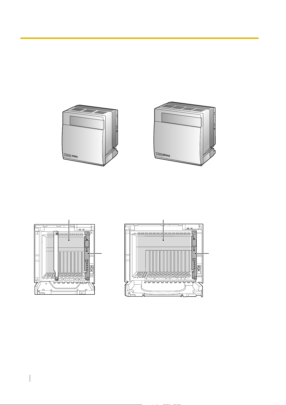
1.2.1 Basic Shelf
The basic shelf contains an MPR card for controlling the Hybrid IP-PBX. To use the system, install a power
supply unit (PSU) in the PSU Slot and optional service cards in the basic shelf.
KX-TDA100 KX-TDA200
Construction of the Basic Shelf
A: Slots for Expansion
B: MPR Card
A A
B B
20 Installation Manual
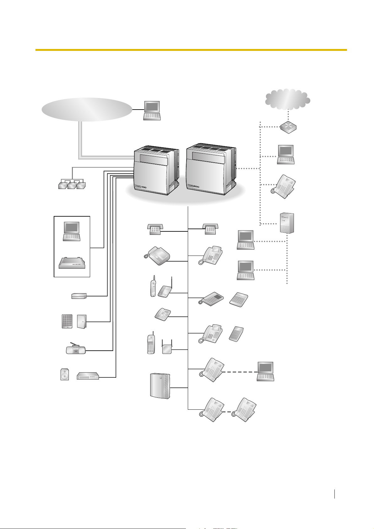
1.2.2 System Connection Diagram
Trunk (Telephone Company Lines)
Analogue/BRI/PRI/T1/E1
Remote PC
1.2 Basic System Construction
Private
IP Network
Batteries
PC
Printer
External Sensor/
External Relay Device
Hybrid IP-PBX
SLT
Fax Machine
Wireless Phone
SLT
DPT
APT
Router
PC
IP-PT
CTI Server
PC
PC
DSS Console
Doorphone & Door Opener
BGM/Music On Hold (MOH)
Pager/
Speaker
Amplifier
ISDN Telephone
CSPS
Voice Processing
System
DPT
DSS Console
USB
KX-T7636/
KX-T7633
KX-T7600 DPT KX-T7600 DPT
PC
Installation Manual 21
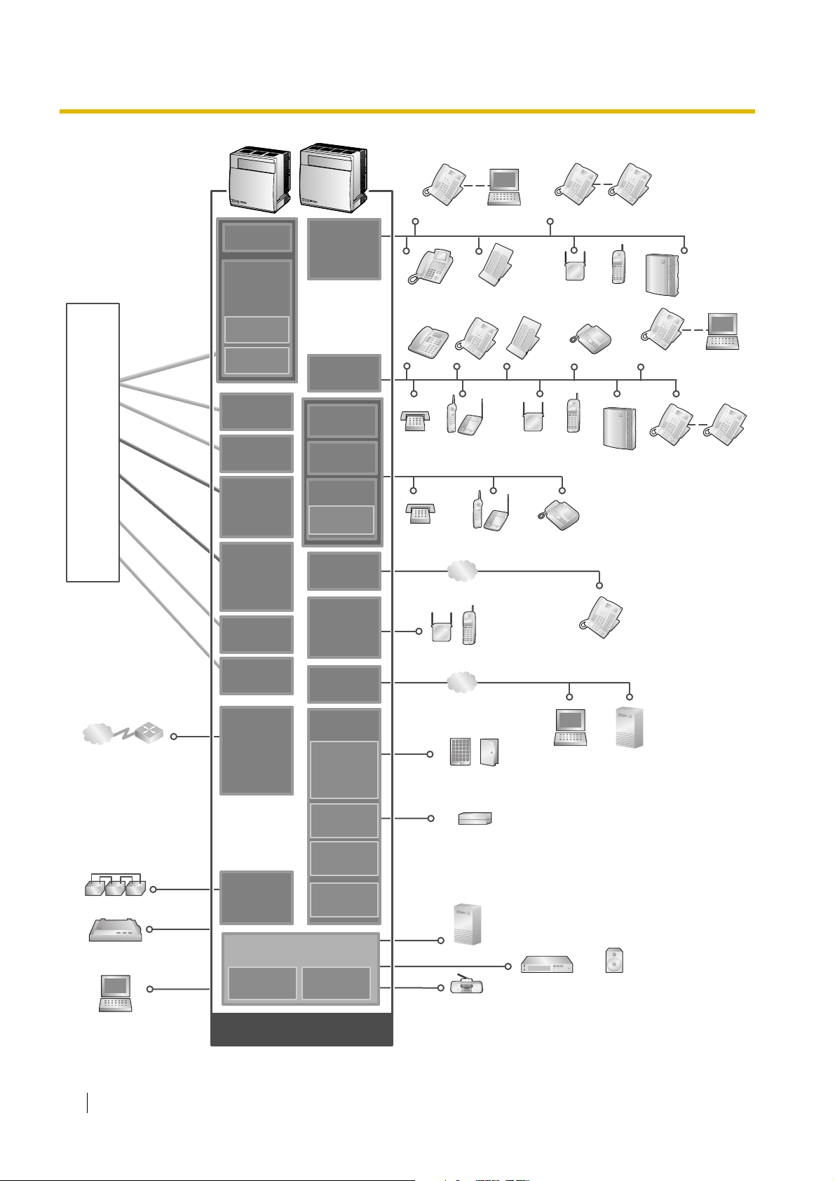
1.2 Basic System Construction
ISDN BRI Line
(Digital Trunk)
ISDN PRI Line
(Digital Trunk)
T1 Line
(Digital Trunk)
Analogue
Trunk
E & M Line
E1 Line
(Digital Trunk)
Hybrid IP-PBX
Telephone
Company
Private
IP Network
Analogue
Analogue
Trunk
Trunk
E & M Line
E & M Line
ISDN BRI Line
ISDN BRI Line
(Digital Trunk)
(Digital Trunk)
ISDN PRI Line
ISDN PRI Line
(Digital Trunk)
(Digital Trunk)
T1 Line
T1 Line
(Digital Trunk)
(Digital Trunk)
E1 Line
E1 Line
(Digital Trunk)
(Digital Trunk)
Router
LCOT4
LCOT4
(KX-TDA0183)
(KX-TDA0183)
LCOT16
LCOT16
(KX-TDA0181)
(KX-TDA0181)
LCOT8
LCOT8
(KX-TDA0180)
(KX-TDA0180)
CID/PAY8
(KX-TDA0189)
CID8
(KX-TDA0193)
DID8
(KX-TDA0182)
E&M8
(KX-TDA0184)
BRI4
(KX-TDA0284)
BRI8
(KX-TDA0288)
PRI30
(KX-TDA0290
CE/CJ)
PRI23
(KX-TDA0290)
T1
(KX-TDA0187)
E1
(KX-TDA0188)
IP-GW4
(KX-TDA0480)
IP-GW4E
(KX-TDA0484)
IP-GW16
(KX-TDA0490)
DLC16
(KX-TDA0172)
DLC8
(KX-TDA0171)
DHLC8
(KX-TDA0170)
MSLC16
(KX-TDA0175)
SLC16
(KX-TDA0174)
SLC8
(KX-TDA0173)
EXT-CID
(KX-TDA0168)
IP-EXT16
(KX-TDA0470)
CSIF4
(KX-TDA0143)
CSIF8
(KX-TDA0144)
CTI-LINK
(KX-TDA0410)
OPB3
(KX-TDA0190)
DPH4
(KX-TDA0161)
DPH2
(KX-TDA0162)
KX-T7636/
KX-T7633
DPT
APT
SLT Wireless Phone
SLT Wireless Phone Fax Machine
LAN
CS PS
LAN
Doorphone & Door Opener
PC
DSS Console
DSS Console
DPT
PT-interface CS
KX-T7600
DPT
PT-interface CS PS
PC
Fax Machine
PS
Voice
Processing
System
IP-PT
CTI Server
KX-T7600
DPT
KX-T7636/
KX-T7633
KX-T7600
DPT
Voice
Processing
System
PC
KX-T7600
DPT
Batteries
Station Message
Detail Recording (SMDR)
PC
22 Installation Manual
(KX-TDA0164)
ECHO16
(KX-TDA0166)
PSU-S/M/L
(KX-TDA0108/
KX-TDA0104/
KX-TDA0103)
(Installed by default)
MEC
(KX-TDA0105)
(KX-TDA0191)
MPR
RMT
(KX-TDA0196)
Mountable Equipment
EIO4
External Sensor/External Relay Device
MSG4
CTI Server
Amplifier Pager/Speaker
Radio

1.3 Optional Equipment
1.3 Optional Equipment
1.3.1 Optional Equipment
Model No. Model Name Description
KX-TDA0103 L-Type Power Supply Unit (PSU-L) Power Supply Unit for KX-TDA200. Total power
output of 279 W. Safety Class 1 compliant.
KX-TDA0104 M-Type Power Supply Unit (PSU-M) Power Supply Unit for KX-TDA100 and KX-TDA200.
Total power output of 140.4 W. Safety Class 1
compliant.
KX-TDA0105 Memory Expansion Card (MEC) Memory expansion card to increase system data
storage space, enable Broadcasting and Call Billing
for Guest Room features, and double the number of
DPTs, using Digital XDP connection. To be mounted
on the MPR card.
KX-TDA0108 S-Type Power Supply Unit (PSU-S) Power Supply Unit for KX-TDA100. Total power
output of 74 W. Safety Class 1 compliant.
KX-TDA0143 4 Cell Station Interface Card (CSIF4) 4-port CS interface card for 4 CSs.
KX-TDA0144 8 Cell Station Interface Card (CSIF8) 8-port CS interface card for 8 CSs.
KX-TDA0161 4-Port Doorphone Card (DPH4) 4-port doorphone card for 4 doorphones and 4 door
openers. To be mounted on the OPB3 card.
KX-TDA0162 2-Port Doorphone Card (German
Type) (DPH2)
KX-TDA0164 4-Port External Input/Output Card
(EIO4)
KX-TDA0166 16-Channel Echo Canceller Card
(ECHO16)
KX-TDA0168 Extension Caller ID Card (EXT-CID) Sends Caller ID signals to extension ports. To be
KX-TDA0170 8-Port Digital Hybrid Extension Card
(DHLC8)
KX-TDA0171 8-Port Digital Extension Card (DLC8) 8-port digital extension card for DPTs, DSS
KX-TDA0172 16-Port Digital Extension Card
(DLC16)
2-port doorphone card for 2 German-type
doorphones and 2 door openers. To be mounted on
the OPB3 card.
4-port external input/output card. To be mounted on
the OPB3 card.
16-channel card for echo cancellation during
conferences. To be mounted on the OPB3 card.
mounted on the SLC8 card only.
8-port digital hybrid extension card for DPTs, APTs,
SLTs, DSS consoles, and PT-interface CSs, with 2
power failure transfer (PFT) ports.
consoles, and PT-interface CSs.
16-port digital extension card for DPTs, DSS
consoles, and PT-interface CSs.
KX-TDA0173 8-Port Single Line Telephone
Extension Card (SLC8)
KX-TDA0174 16-Port Single Line Telephone
Extension Card (SLC16)
8-port extension card for SLTs with 2 power failure
transfer (PFT) ports.
16-port extension card for SLTs with 4 power failure
transfer (PFT) ports.
Installation Manual 23

1.3 Optional Equipment
Model No. Model Name Description
KX-TDA0175 16-Port Single Line Telephone
Extension with Message Lamp Card
(MSLC16)
16-port extension card for SLTs with Message
Waiting Lamp control and 4 power failure transfer
(PFT) ports. Maximum power output of 160 V/90 V
for Message Waiting Lamp control.
KX-TDA0180 8-Port Analogue Trunk Card (LCOT8) 8-port analogue trunk card with 2 power failure
transfer (PFT) ports.
KX-TDA0181 16-Port Analogue Trunk Card
(LCOT16)
16-port analogue trunk card with 4 power failure
transfer (PFT) ports.
KX-TDA0182 8-Port DID Card (DID8) 8-port DID trunk card.
KX-TDA0183 4-Port Analogue Trunk Card (LCOT4) 4-port analogue trunk card with 2 power failure
transfer (PFT) ports.
KX-TDA0184 8-Port E & M Trunk Card (E&M8) 8-port E & M (TIE) trunk card. Type 5 support.
KX-TDA0187 T-1 Trunk Card (T1) 1-port T1 trunk card. EIA/TIA standard compliant.
KX-TDA0188 E-1 Trunk Card (E1) 1-port E1 trunk card. ITU-T standard compliant.
KX-TDA0189 8-Port Caller ID/Pay Tone Card (CID/
PAY 8)
8-port Caller ID signal type FSK/FSK (with Call
Waiting Caller ID [Visual Caller ID])/DTMF, and 8port Pay Tone Service (12 kHz/16 kHz). To be
mounted on the LCOT8/LCOT16 cards.
KX-TDA0190 Optional 3-Slot Base Card (OPB3) Optional 3-slot base card for mounting a maximum
of 3 option cards from the following: MSG4, DPH4,
DPH2, or ECHO16 card.
KX-TDA0191 4-Channel Message Card (MSG4) 4-channel message card. To be mounted on the
OPB3 card.
KX-TDA0193 8-Port Caller ID Card (CID8) 8-port Caller ID signal type FSK/FSK (with Call
Waiting Caller ID [Visual Caller ID])/DTMF. To be
mounted on the LCOT8/LCOT16 cards.
KX-TDA0196 Remote Card (RMT) Analogue modem card for remote communication
with the Hybrid IP-PBX. ITU-T V.90 support. To be
mounted on the MPR card.
KX-TDA0284 4-Port BRI Card (BRI4) 4-port ISDN Basic Rate Interface card with 1 power
failure transfer port. EURO-ISDN/ETSI compliant.
KX-TDA0288 8-Port BRI Card (BRI8) 8-port ISDN Basic Rate Interface card with 1 power
failure transfer port. EURO-ISDN/ETSI compliant.
KX-TDA0290CE/CJ PRI Card (PRI30) 1-port ISDN Primary Rate Interface card (30B
channels). EURO-ISDN/ETSI compliant.
KX-TDA0290 PRI Card (PRI23) 1-port ISDN Primary Rate Interface card (23B
channels). NI (North American standard ISDN
protocol) compliant.
KX-TDA0410 CTI Link Card (CTI-LINK) Ethernet card for CTI communication via 10BASE-T
port. CSTA Phase 3 protocol compatible.
KX-TDA0470 16-Channel VoIP Extension Card (IP-
EXT16)
16-channel VoIP extension card. Compliant with
Panasonic proprietary protocol, and ITU-T G.729a
and G.711 CODEC methods.
24 Installation Manual

1.3 Optional Equipment
Model No. Model Name Description
KX-TDA0480 4-Channel VoIP Gateway Card (IP-
GW4)
KX-TDA0484 4-Channel VoIP Gateway Card (IP-
GW4E)
KX-TDA0490 16-Channel VoIP Gateway Card (IP-
GW16)
KX-TDA0820 SD Memory Card for Software
Upgrade
KX-TDA0920 SD Memory Card for Software
Upgrade to Enhanced Version
Note
For the maximum number of optional service cards that can be installed in the Hybrid IP-PBX, refer to
"1.4.3 System Capacity".
4-channel VoIP gateway card. Compliant with VoIP
H.323 V.2 protocol, and ITU-T G.729a and G.723.1
CODEC methods. G3 fax support.
4-channel VoIP gateway card. Compliant with VoIP
H.323 V.2 protocol, and ITU-T G.729a, G.723.1, and
G.711 CODEC methods.
16-channel VoIP gateway card. Compliant with VoIP
H.323 V.2 protocol, and ITU-T G.729a, G.723.1, and
G.711 CODEC methods.
Optional SD Memory Card to upgrade PMPR file
version 1.xxxx Hybrid IP-PBX. For more details,
refer to the SD Memory Card Installation/Upgrade
Guide.
Optional SD Memory Card to use enhanced
features. For more details, refer to the SD Memory
Card Installation/Upgrade Guide.
Installation Manual 25

1.4 Specifications
C˚C
1.4 Specifications
1.4.1 General Description
Control Bus Original bus (16-bit, 8 MHz, 10 megabytes per second)
Communication Bus H.100 bus conformity (1024 time slots)
Switching Non-blocking
Power Input PSU-S 100 V AC to 130 V AC, 1.4 A/200 V AC to 240 V AC, 0.8 A,
50 Hz/60 Hz
PSU-M 100 V AC to 130 V AC, 2.5 A/200 V AC to 240 V AC, 1.4 A,
50 Hz/60 Hz
PSU-L 100 V AC to 130 V AC, 5.1 A/200 V AC to 240 V AC, 2.55 A,
50 Hz/60 Hz
External Battery +36 V DC (+12 V DC × 3, recommended maximum capacity
is 28 Ah)
Maximum Power Failure Tolerance 300 ms (without using backup batteries)
Memory Backup Duration 7 years
Dialling Trunk Dial Pulse (DP) 10 pps, 20 pps
Tone (DTMF) Dialling
Extension Dial Pulse (DP) 10 pps, 20 pps
Tone (DTMF) Dialling
Mode Conversion DP-DTMF, DTMF-DP
Ring Frequency 20 Hz/25 Hz (selectable)
Trunk Loop Limit 1600 Ω maximum
Operating
Environment
Conference Call Trunk From 10 × 3-party conference call to 4 × 8-party conference
Music on Hold (MOH) 2 ports (Level Control: -11 dB to +11 dB in 1 dB steps)
Paging Internal Level Control: -15 dB to +6 dB in 3 dB steps
Temperature
Humidity 10 % to 90 % (non-condensing)
External 2 ports (Volume Control: -15 dB to +15 dB in 1 dB steps)
˚
0 to 40
call
MOH1: External Music Source port
MOH2: Selectable Internal/External Music Source port
Serial Interface Port RS-232C 1 (maximum 115.2 kbps)
USB 1
26 Installation Manual
1.4 Specifications
Extension Connection Cable SLT 1-pair wire (T, R)
DPT 1-pair wire (D1, D2) or
2-pair wire (T, R, D1, D2)
APT 2-pair wire (T, R, D1, D2)
PT-interface CS 1-pair wire (D1, D2)
DSS Console and Add-on
1-pair wire (D1, D2)
Key Module
Dimension KX-TDA100 334 mm (W) × 390 mm (H) × 270 mm (D)
KX-TDA200 430 mm (W) × 415 mm (H) × 270 mm (D)
Weight (when fully
mounted)
KX-TDA100 Under 12 kg
KX-TDA200 Under 16 kg
Installation Manual 27

1.4 Specifications
1.4.2 Characteristics
Terminal Equipment Loop Limit • PT: KX-T7600 series DPT: 90 Ω; all other DPTs/APTs: 40 Ω
• SLT: 600 Ω including set
• Doorphone: 20 Ω
• CS: 130 Ω; PT-interface CS: 65 Ω
Minimum Leakage Resistance 15 000 Ω minimum
Maximum Number of Extension
Instruments per Line
Ring Voltage 75 Vrms at 20 Hz/25 Hz depending on the Ringing Load
Trunk Loop Limit 1600 Ω maximum
Hookswitch Flash/Recall Timing
Range
BRI Cards Internal ISDN Mode Supply Voltage: 40 V
Door Opener Current Limit 24 V DC/30 V AC, 1 A maximum
External Relay Current Limit 24 V DC/30 V AC, 1 A maximum
External Sensor Current Limit Power to the external sensor is provided from the EIO4 card and must be
Paging Terminal Impedance 600 Ω
MOH (Music on Hold) Terminal
Impedance
1 for PT or SLT
2 by Parallel or eXtra Device Port connection of an APT/DPT and an SLT
3 by Digital eXtra Device Port connection of 2 DPTs and an SLT
24 ms to 2032 ms
Power Supply (BRI4): 4.5 W per 1 line, 10 W per 4 lines
Power Supply (BRI8): 4.5 W per 1 line, 20 W per 8 lines
Power Supply Method: Phantom Power Supply
grounded through the EIO4 card. For the connection diagram, refer to
"2.6.4 EIO4 Card (KX-TDA0164)". The Hybrid IP-PBX detects input from
the sensor when the signal is under 100 Ω.
10 000 Ω
28 Installation Manual
1.4.3 System Capacity
Maximum Optional Service Cards
There are 2 types of optional service cards for installation:
• Cards installed in the slots of the Hybrid IP-PBX
• Cards mounted on other optional service cards
Notes
• Any card that exceeds the capacity of the Hybrid IP-PBX will be ignored.
• When the Hybrid IP-PBX starts up with an invalid configuration, some cards will be ignored.
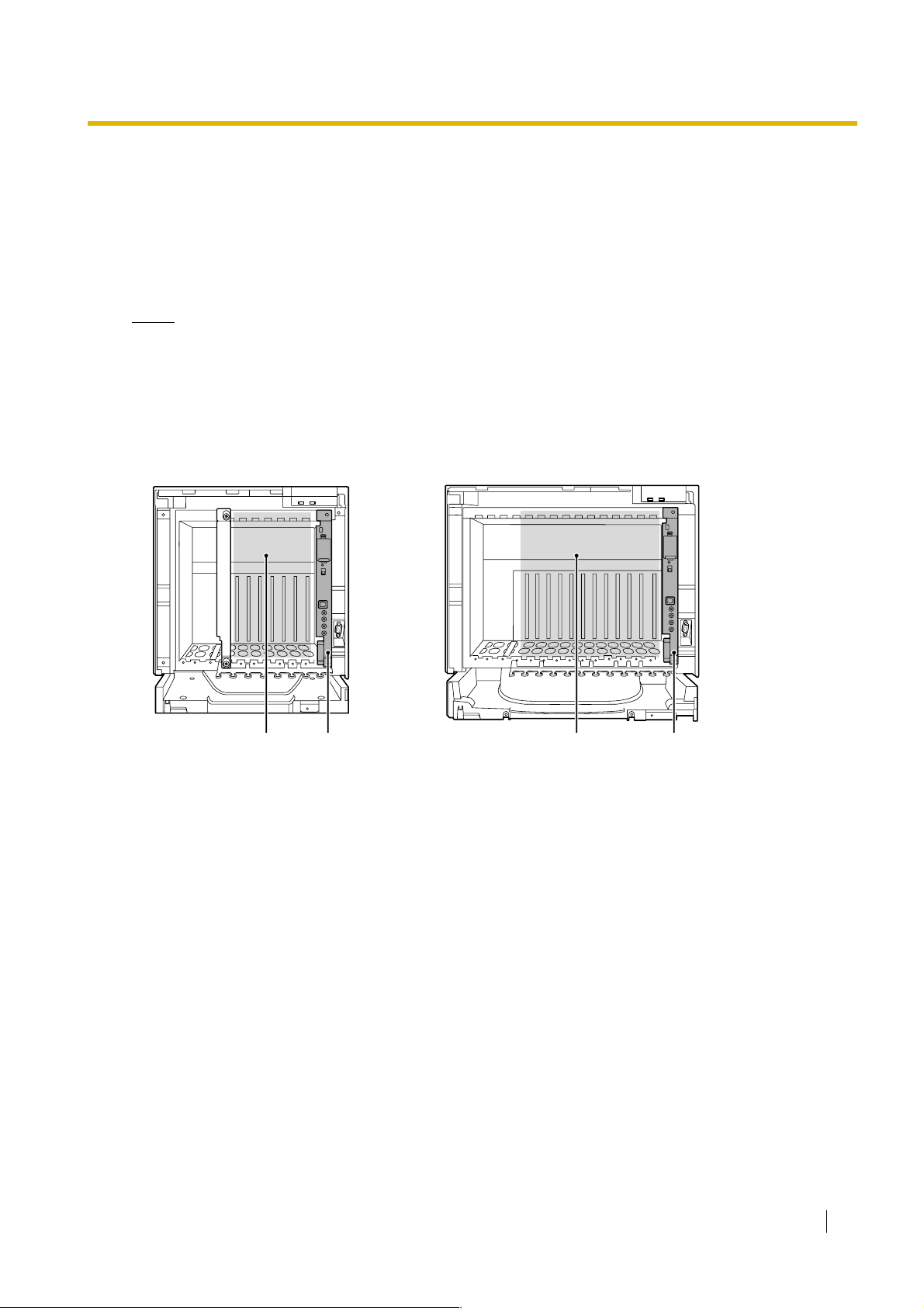
Cards Installed in the Slots of the Hybrid IP-PBX
KX-TDA100 KX-TDA200
1.4 Specifications
AB C B
Free Slots 1 to 6 (from the left)
A.
B. MPR Card Slot
C. Free Slots 1 to 11 (from the left)
Installation Manual 29

1.4 Specifications
The following number of optional service cards can be installed in the various slots of the Hybrid IP-PBX.
Card Type
Installed in
KX-TDA100 KX-TDA200
MPR 1 1 MPR Card Slot
Maximum Number
Trunk Card
Tot al 6
*1
To ta l 8
*2
LCOT4
LCOT8
LCOT16
DID8
68
E&M8
BRI4
Free Slot
BRI8
T1
E1
44
PRI23
PRI30
IP-GW4
IP-GW4E
IP-GW16
44
30 Installation Manual
Loading...