


 Loading...
16-Channel VoIP Gateway Card
Getting Started
Model No. KX-TDA0490
Thank you for purchasing a Panasonic 16-Channel VoIP Gateway Card.
Please read this manual carefully before using this product and save this manual for future use.

Table of Contents
1 Overview.................................................................................................. |
5 |
|
1.1 |
Example Network Diagram............................................................................................... |
6 |
1.2 |
Network Devices and Numbering Plan ........................................................................... |
7 |
1.2.1 |
Network Application ............................................................................................................ |
8 |
1.2.2 |
Numbering Plan Example ................................................................................................... |
9 |
1.2.3 |
Numbering Plan Summary................................................................................................ |
12 |
2 Installing in the PBX............................................................................. |
13 |
|
2.1 |
Installation ....................................................................................................................... |
14 |
2.1.1 |
Names and Locations ....................................................................................................... |
14 |
2.1.2 |
Installing the VoIP Gateway Card in the PBX.................................................................... |
15 |
2.2 |
Cable Connection............................................................................................................ |
17 |
2.2.1 |
Attaching a Ferrite Core to the Cable................................................................................ |
17 |
2.2.2 |
Connection for Programming ............................................................................................ |
18 |
2.2.3 |
Connection to the LAN ...................................................................................................... |
19 |
3 Programming the VoIP Gateway Card ................................................ |
21 |
|
3.1 |
Preparations .................................................................................................................... |
22 |
3.1.1 |
Preparing the PC .............................................................................................................. |
22 |
3.2 |
Programming the VoIP Gateway Card in the Los Angeles Office............................... |
25 |
3.2.1 |
Starting the IP-GW16 Maintenance Utility ........................................................................ |
25 |
3.2.2 |
Changing the Status of the VoIP Gateway Card ............................................................... |
27 |
3.2.3 |
Assigning the IP Address .................................................................................................. |
28 |
3.2.4 |
Assigning the Hunt Pattern ............................................................................................... |
29 |
3.2.5 |
Programming the Address Translation Table..................................................................... |
31 |
3.2.6 |
Downloading the Address Translation Table from the VoIP Gateway Card ....................... |
34 |
3.2.7 |
Rebooting the VoIP Gateway Card ................................................................................... |
35 |
3.2.8 |
Confirming the IP Address Assignment ............................................................................ |
36 |
3.3 |
Programming the VoIP Gateway Card in the Chicago Office ...................................... |
37 |
4 |
Programming the PBX.......................................................................... |
41 |
4.1 |
Programming the PBX in the Los Angeles Office........................................................ |
42 |
A Guidance for VoIP Installation............................................................. |
45 |
|
A1 |
VoIP Requirements ......................................................................................................... |
46 |
A1.1 |
Bandwidth Assessment..................................................................................................... |
46 |
A1.2 |
Network Configuration....................................................................................................... |
48 |
A1.3 |
Network Devices ............................................................................................................... |
51 |
A1.4 |
QoS (Quality of Service) ................................................................................................... |
52 |
A2 |
VoIP Requirements Checklist......................................................................................... |
53 |
B Alternative Numbering Plan Example................................................. |
55 |
|
B1 |
Extension Number Method............................................................................................. |
56 |
B1.1 |
Example Network .............................................................................................................. |
56 |
B1.2 |
Numbering Plan Example ................................................................................................. |
57 |
B2 |
Programming for the Extension Number Method ........................................................ |
59 |
B2.1 |
Programming the VoIP Gateway Card .............................................................................. |
59 |
B2.2 |
Programming the PBX in the Los Angeles Office ............................................................. |
61 |
2 Getting Started

C |
Initialisation of the VoIP Gateway Card............................................... |
63 |
|
C1 |
Initialising the VoIP Gateway Card................................................................................ |
64 |
|
D |
Using the KX-TDA0490 and KX-TDA0480 in One Network ................ |
67 |
|
D1 |
Considerations in Installation ....................................................................................... |
68 |
|
Getting Started |
3 |
|
|

4 Getting Started

Section 1
Overview
Panasonic PBX with VoIP Gateway Card will allow organisations to route both voice and fax communications over digital data networks.
The VoIP Gateway Card, designed to be easily integrated into existing IP networks, seamlessly bridges Public Switched Telephone Network (PSTN) and analogue telephones with digital data networks without interrupting pre-existing data communications. Because communications do not take place over conventional telephone networks, the high cost of long distance communications is virtually eliminated.
Getting Started |
5 |
|
|

1.1 Example Network Diagram
1.1Example Network Diagram
The following diagram illustrates a simple VoIP network connecting PBXs at 2 locations. The VoIP Gateway Card converts outgoing voice or fax signals into IP packets for transmission. On the incoming side, it reverses this process and translates the packets back into appropriate voice or fax signals.
PSTN
(Public Switched
Telephone Network)
Switching Hub
Voice signals are converted into IP packets.
Hybrid IP-PBX
with a VoIP Gateway Card
Router
Voice data packets
IP Network
Other data packets
IP packets are converted back into voice signals.
PSTN
6 Getting Started

1.2 Network Devices and Numbering Plan
1.2Network Devices and Numbering Plan
You will need to have network configuration information available to install VoIP Gateway Cards. Referring to this example diagram, consult your network administrator to obtain necessary information to configure your own VoIP network.
Extn. 201 G3 Fax Extn. 501
Local Telephone (200-299) (500-599)
456-7890
PSTN
(Public Switched
Telephone Network)
Card IP: 200.45.11.35 |
Subnet Mask: 255.255.255.0 |
|
|
PBX Code: 35 |
Default Gateway IP: 200.45.11.1 |
PSTN Trunk Number: 9 |
|
TIE Line Access Number: 7 |
|
Los Angeles Office
IP Network
Chicago Office
PBX Code: 41
PSTN Trunk Number: 9
Default Gateway IP: 199.176.64.1 |
TIE Line Access Number: 7 |
|
Card IP: 199.176.64.41
Subnet Mask: 255.255.255.0
|
|
PSTN |
|
G3 Fax Extn. 601 |
Extn. 301 |
Local Telephone |
|
123-4567 |
|||
(600-699) |
(300-399) |
||
|
Getting Started |
7 |
|
|

1.2 Network Devices and Numbering Plan
1.2.1Network Application
QSIG Network Interface
QSIG is a protocol based on ISDN (Q.931) that offers enhanced PBX features in a private network. The QSIG network supports private communications by the TIE line service method. Implementation of VoIP Gateway Cards provides a VoIP interface to employ a QSIG network between PBXs at different locations by using an IP network instead of conventional telephone networks.
Types of IP Network
The VoIP Gateway Card's quality of performance depends on the type of IP network in use. Managed IP networks provide better quality of service compared to unmanaged networks, where quality of service is not guaranteed.
Examples of recommended IP networks
•Digital Leased Line
•IP-VPN (Virtual Private Network)
•Frame Relay
Notice
The performance of the VoIP Gateway Card may deteriorate when it is used on the Internet. Delays and loss in data transmission can degrade speech quality, and impair the card's capability to use the enhanced networking features of the PBX (for more information about these features, refer to the relevant sections of the Hybrid IP-PBX documentation.)
Firewall
A firewall protects the internal networks of an organisation against unauthorised penetration from outside. When routing a VoIP network through a firewall, some performance degradation may result. If for practical reasons you must route the VoIP network through a firewall, refer to "A1.3 Network Devices" for more details.
Using the KX-TDA0490 with Other KX-TDA Series VoIP Gateway Cards
When using the KX-TDA0490 in a network that contains other KX-TDA series VoIP Gateway Cards, keep in mind the following points:
1.Making and Receiving Calls
Calls can be made and received between the KX-TDA0490 and other KX-TDA series VoIP Gateway Cards. However, the KX-TDA0480 requires a special setting to be able to communicate with the KX-TDA0490 on the network. Refer to "D1 Considerations in Installation" for more details.
2.Using QSIG Services
All QSIG services available with the PBX can be used between the KX-TDA0490 and KX- TDA0484/KX-TDA3480. However, CLIP service is the only available QSIG service between the KX-TDA0490 and KX-TDA0480.
8 Getting Started

1.2 Network Devices and Numbering Plan
1.2.2Numbering Plan Example
There are 2 methods to plan your numbering system, as follows:
|
In addition to the destination number, the caller dials the unique PBX code of the |
PBX code |
PBX to which the called party is connected. Therefore, extension numbers at |
method |
separate PBXs in the network can overlap. For example, each PBX in the |
|
network can have an extension whose number is 201. |
|
|
|
The caller dials only the destination number of the called party to call through |
|
PBXs at different locations (hence there are fewer digits to dial than with the PBX |
Extension |
code method). To employ the extension number method, no 2 PBXs can have |
number method |
extensions sharing the same number. For example, if one PBX in the network |
|
has an extension whose number is 201, no other PBX can have an extension |
|
with the same number (201). |
|
|
This section provides a network numbering mechanism using the PBX code method based on the previous example diagram. Configure your network referring to this example.
Note
An example using the extension number method is provided in "B Alternative Numbering Plan Example".
IP Addressing Information
IP addressing information is typically supplied by a network administrator. Consult your network administrator for specific values.
|
Los Angeles |
Chicago |
Description |
|
Office |
Office |
|
|
|
|
|
|
|
|
Identifies the location of each VoIP Gateway |
Card IP Address |
200.45.11.35 |
199.176.64.41 |
Card in the network during VoIP |
communications. A unique IP address must |
|||
|
|
|
be assigned to each card. |
|
|
|
|
|
|
|
Identifies the IP address of the primary |
Default Gateway |
200.45.11.1 |
199.176.64.1 |
gateway (typically a router or similar device) |
Address |
|
|
that exchanges IP packets with the other |
|
|
|
gateways on the VoIP network. |
|
|
|
|
|
|
|
Defines which digits of an IP address are |
|
|
|
used for the network address and the host |
Subnet Mask |
255.255.255.0 |
255.255.255.0 |
address at each network location. A card IP |
Address |
address must fall within the same subnet as |
||
|
|
|
that of the default gateway (e.g., router) that |
|
|
|
is connected to the card. |
|
|
|
|
Getting Started |
9 |
|
|

1.2 Network Devices and Numbering Plan
PBX Numbering Information
PBX numbering information is necessary to set up phone numbers for a VoIP network. Set the numbers conforming to existing PBX numbering systems.
|
Los Angeles |
Chicago |
Description |
|
|
Office |
Office |
|
|
|
|
|
|
|
|
|
|
A unique number (ranging from 1 to 7 digits) |
|
|
|
|
assigned to identify each PBX within a |
|
|
|
|
network. |
|
PBX Code |
35 |
41 |
In this example, for convenience, each PBX |
|
code corresponds to the last portion of the |
||||
|
|
|
||
|
|
|
IP address of its card; that is, because the |
|
|
|
|
Los Angeles office card has the IP address |
|
|
|
|
200.45.11.35, Los Angeles PBX code is 35. |
|
|
|
|
|
|
TIE Line Access |
7 |
7 |
An access number to use the TIE line |
|
Number |
service. |
|||
|
|
|||
|
|
|
|
|
PSTN Trunk Number |
9 |
9 |
An access number to seize a local PSTN |
|
trunk. |
||||
|
|
|
||
|
|
|
|
|
Extension Number |
200 to 299 |
300 to 399 |
A number assigned to each extension. |
|
|
|
|
|
|
Fax Extension |
500 to 599 |
600 to 699 |
A number assigned to each fax extension. |
|
Number |
||||
|
|
|
||
|
|
|
|
Dialling Examples
The VoIP network allows you to access the PBX at one location from another to establish: (1) an extension call, or (2) an outside call through the local PSTN as if you are calling from the same area.
Calling from Los Angeles to Chicago
To extension 301 via VoIP network
TIE line |
Chicago |
extension no. |
|
access no. |
PBX code |
||
|
|||
Dial 7. |
Dial 41. |
Dial 301. |
|
|
|
|
To local telephone 123-4567 via VoIP network through local PSTN
TIE line |
Chicago |
Chicago PBX |
phone no. |
|
access no. |
PBX code |
PSTN trunk no. |
||
|
||||
Dial 7. |
Dial 41. |
Dial 9. |
Dial 123-4567. |
|
|
|
|
|
Calling from Chicago to Los Angeles
To extension 201 via VoIP network
TIE line |
Los Angeles |
extension no. |
|
access no. |
PBX code |
||
|
|||
Dial 7. |
Dial 35. |
Dial 201. |
|
|
|
|
10 Getting Started
1.2 Network Devices and Numbering Plan
To local telephone 456-7890 via VoIP network through local PSTN
TIE line |
Los Angeles |
Los Angeles PBX |
phone no. |
|
access no. |
PBX code |
PSTN trunk no. |
||
|
||||
Dial 7. |
Dial 35. |
Dial 9. |
Dial 456-7890. |
|
|
|
|
|
PBX Connection Information
PBX connection information is created by combining IP Addressing Information and PBX Numbering Information. Referring to the sample below, create your own PBX connection information.
Leading Number:
A number composed of the PBX code followed by the first digit of the destination number. See the example on the right.
Remaining Digits:
Los Angeles extensions
Leading No. Remaining Digits
352+00 to 99
The maximum number of digits to be dialled following the leading number to access the destination. (However, for example, setting the remaining digits to 7 does not mean that the user must dial all 7 digits when making a call.) See the example on the right.
Card IP Address:
PBX Code First digit of |
Remaining digits |
the extension |
of the extension |
number |
number |
The IP address of each card in the network (as the access destination).
|
Los Angeles Office (PBX Code: 35) |
Chicago Office (PBX Code: 41) |
||||||
|
|
|
|
|
|
|
|
|
|
Extn. |
FAX Extn. |
PSTN |
Extn. |
|
FAX Extn. |
|
PSTN |
|
|
|
Access |
|
|
|
|
Access |
|
|
|
|
|
|
|
|
|
Leading Number |
352 |
355 |
359 |
413 |
|
416 |
|
419 |
|
|
|
|
|
|
|
|
|
Remaining Digits |
2 |
2 |
7 |
2 |
|
2 |
|
7 |
|
|
|
|
|
|
|
|
|
Card IP Address |
|
200.45.11.35 |
|
|
199.176.64.41 |
|
||
|
|
|
|
|
|
|
|
|
Getting Started |
11 |
|
|

1.2 Network Devices and Numbering Plan
1.2.3Numbering Plan Summary
Print this page and write down your network information in the space provided below for each card in the network. Consult your network administrator to fill in the shaded entries.
Local Telephone: |
Extension Number: |
G3 Fax Extension Number: |
PSTN
(Public Switched
Telephone Network)
Card IP: |
Subnet Mask: |
|
PBX Code:
PSTN Trunk Number: Default Gateway IP:
TIE Line Access Number:
IP Network
IP Address
Card IP Address
Default Gateway IP Address
Subnet Mask Address
PBX Numbering
PBX Code
TIE Line Access Number
PSTN Trunk Number
Extension Number
Fax Extension Number
PBX Connection
Extensions |
Fax Extensions |
PSTN Access |
Leading Number
Remaining Digits
Card IP Address
12 Getting Started

Section 2
Installing in the PBX
This section describes the physical installation process of the VoIP Gateway Card covering the following topics: (1) installing the card in the PBX, and (2) connecting the card to a network device using a Category 5 (CAT5) Ethernet cable.
Getting Started |
13 |
|
|

2.1 Installation
2.1Installation
2.1.1Names and Locations
LEDs
RJ45 (10BASE-T/100BASE-TX Full Duplex)
Indication Light (LED)
When the VoIP Gateway Card is operating, each LED should show the status identified in bold-face letters under normal conditions.
Indication |
Colour |
|
Description |
|
|
|
|
||
|
|
Card status indication |
||
|
|
• |
OFF: Power Off |
|
CARD |
Green/Red |
• |
Green ON: Normal (all ports are idle) |
|
STATUS |
• |
Green Flashing (60 times per minute): Normal (a port is in use) |
||
|
||||
|
|
• Red ON: Fault (includes reset) |
||
|
|
• Red Flashing (60 times per minute): Out of Service |
||
|
|
|
||
|
|
On-line status indication |
||
|
|
• ON: On-line mode |
||
|
|
• OFF: Off-line mode |
||
ONLINE |
Green |
• |
Flashing: Maintenance mode |
|
|
|
Note |
||
|
|
|
If the LINK indicator is OFF, the ONLINE indicator will also be |
|
|
|
|
OFF. |
|
|
|
|
||
|
|
Alarm indication |
||
ALARM |
Red |
• |
ON: Alarm |
|
|
|
• |
OFF: Normal |
|
|
|
|
||
|
|
VoIP (H.323) process indication |
||
VoIP BUSY |
Green |
• |
OFF: VoIP process inactive |
|
|
|
• ON: VoIP process active |
||
|
|
|
|
|
14 Getting Started

2.1 Installation
Indication |
Colour |
|
Description |
|
|
|
|
|
|
Link status indication |
|
LINK |
Green |
• |
ON: Normal connection |
|
|
• |
OFF: Connection error |
|
|
|
|
|
|
Data transmission indication |
|
DATA |
Green |
• |
ON: Data transmitting |
|
|
• OFF: No data transmitted |
|
|
|
|
|
2.1.2Installing the VoIP Gateway Card in the PBX
Install the VoIP Gateway Card in a free slot of the PBX.
Note
The illustrations of the PBX shown in the installation procedure are based on the KX-TDA600.
1.Insert the card along the guide rails.
 Guide Rail
Getting Started |
15 |
|
|

2.1Installation
2.Holding the card as shown below, push the release lever in the direction of the arrow so that the card engages securely with the connector on the back board.
Back Board
Release Lever
3.Turn the 2 screws clockwise to fix the card in place.
Screws
Note
Make sure the screws are tightened to earth the card securely.
16 Getting Started

2.2 Cable Connection
2.2Cable Connection
Use a Category 5 (CAT5) Ethernet cable (10BASE-T/100BASE-TX) with an RJ45 connector to connect the VoIP Gateway Card to a network device.
When connecting the card to a switching hub, use an Ethernet straight cable; when connecting directly to a router or PC, use an Ethernet cross cable.
Note
Use only CAT5 Ethernet cable for connection.
2.2.1Attaching a Ferrite Core to the Cable
When connecting the VoIP Gateway Card to a network device, first attach a ferrite core (included with the card) to the cable.
1.Wrap the cable once around the ferrite core, leaving 5 cm between the ferrite core and the connector.
2.Close the case of the ferrite core.
5 cm
If you need to open the ferrite core, use a flathead screwdriver to unlatch the case of the ferrite core.
Getting Started |
17 |
|
|
2.2 Cable Connection
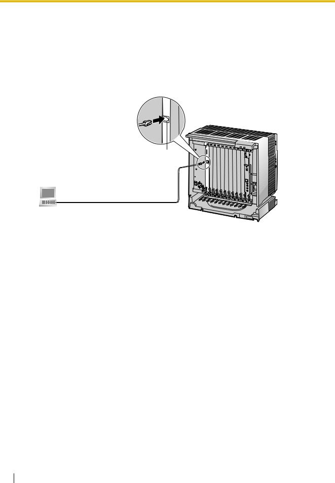
2.2.2Connection for Programming
When assigning a new IP address to the VoIP Gateway Card for the first time, connect a PC directly to the card using an Ethernet cross cable.
1.Connect the Ethernet cable to the RJ45 connector of the card.
2.Connect the other end of the cable to the PC.
RJ45
Ethernet Cross Cable
PC
18 Getting Started
2.2 Cable Connection
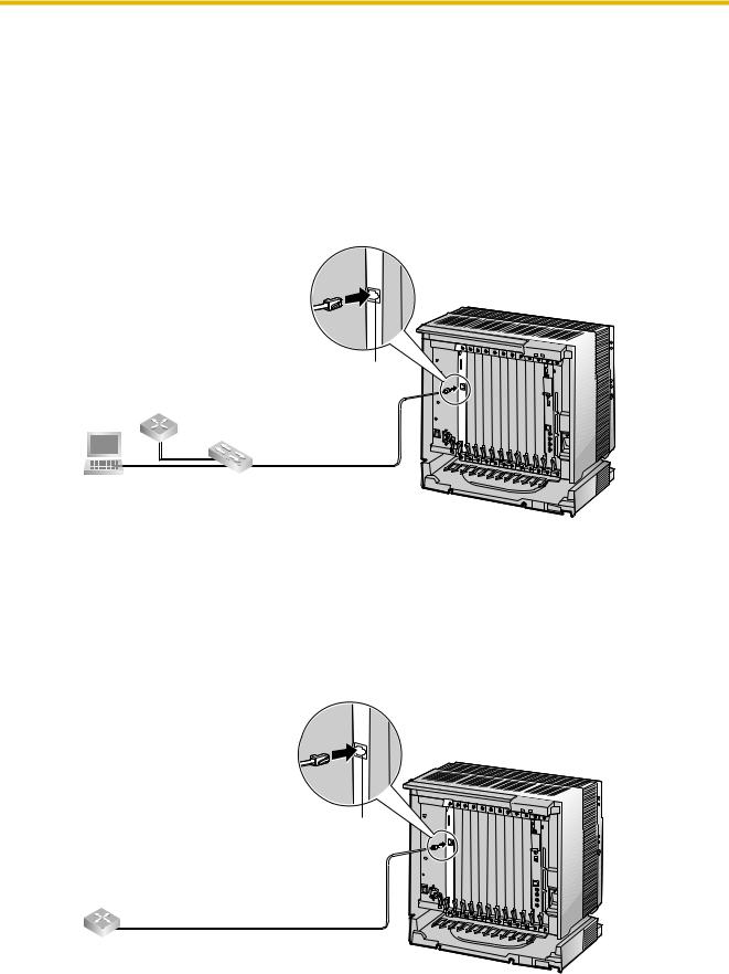
2.2.3Connection to the LAN
Do not connect the VoIP Gateway Card to the LAN unless it has been assigned an IP address for actual VoIP operations on the network. Doing so may result in the default IP address of the card overlapping with an existing IP address on the LAN, or cause network failure.
1.Connect the Ethernet cable to the RJ45 connector of the card.
2.Connect the other end of the cable to the remote LAN equipment.
Connecting to a switching hub
RJ45
Router
Switching Hub
Ethernet Straight Cable
PC
Notes
•Make sure to connect to a switching hub. Do not connect to a repeater hub, as this will result in degradation in speech quality.
•Also, make sure to set the port of the switching hub that connects to the card to operate under "Auto Negotiation" mode. This will help assure error-free communication between the card and the switching hub.
Connecting directly to a router
RJ45
Ethernet Cross Cable
Router
Getting Started |
19 |
|
|

2.2 Cable Connection
20 Getting Started
Section 3
Programming the VoIP Gateway Card
One way of setting up a VoIP network for the first time is to go through the whole programming process of a VoIP Gateway Card at one location in the network, then start programming the other cards at different locations.
Based on the theoretical network illustrated previously in this manual, this section demonstrates the procedure to programme the cards in the Los Angeles and Chicago offices.
Getting Started |
21 |
|
|
3.1 Preparations
3.1Preparations
A web programming utility called the IP-GW16 Maintenance Utility is available for programming of the VoIP Gateway Card.
For a complete discussion of web programming, refer to the VoIP Gateway Card Programming Guide.
System Requirements
•The IP-GW16 Maintenance Utility requires Microsoft® Internet Explorer 5.0 or above.
Trademarks
•Microsoft is either a registered trademark or trademark of Microsoft Corporation in the United States and/or other countries.
•All other trademarks identified herein are the property of their respective owners.
•Screen shots reprinted with permission from Microsoft Corporation.
3.1.1Preparing the PC
To prepare for programming using the IP-GW16 Maintenance Utility, configure your PC by (1) assigning an IP address that belongs to the same network as that of the VoIP Gateway Card, and (2) choosing the appropriate options for the Internet properties.
Note
The procedure below is based on the Windows XP operating system as an example.
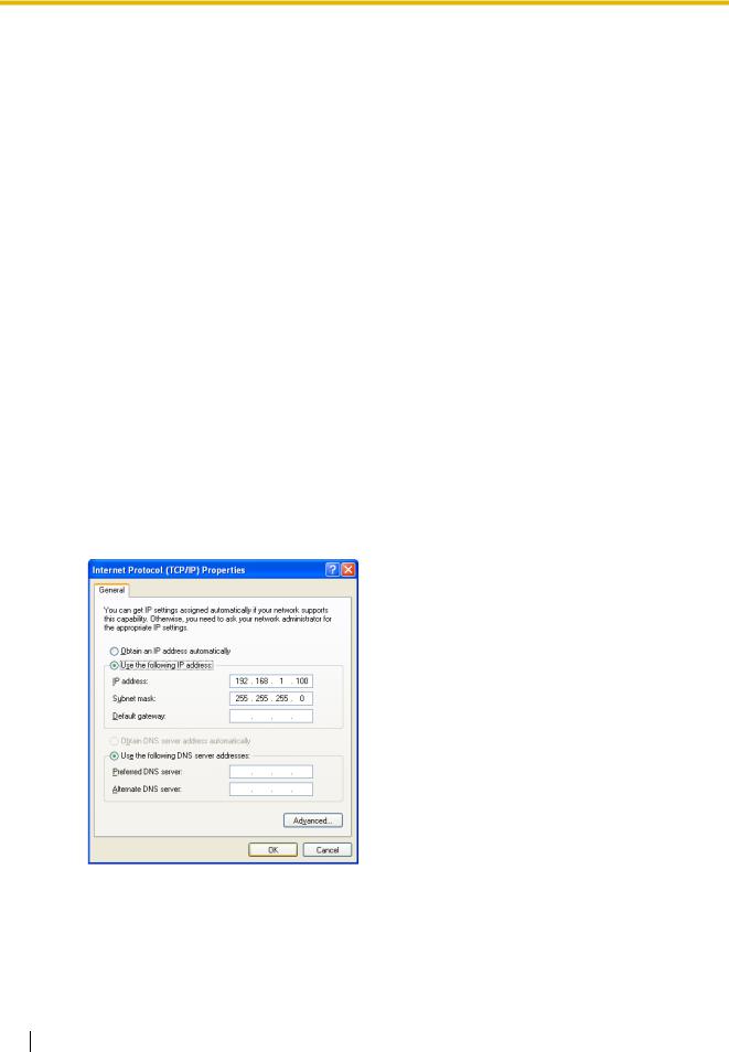
1. Open Internet Protocol (TCP/IP) Properties from the Start menu.
2. a. Click Use the following IP address.
b. In the IP address box, type 192.168.1.100.
This is an example entry for the case when the card has the default IP address (192.168.1.200).
c. In the Subnet mask box, type 255.255.255.0. d. Click OK.
3. a. Start Internet Explorer from the Start menu. b. Click Internet Options from the Tools menu.
22 Getting Started

3.1 Preparations
4.a. Click the Connections tab.
b.Click Never dial a connection.
c.Click LAN Settings.
5.a. Click to clear all check boxes. b. Click OK.
Your PC is now ready for programming through direct access to the card.
Notice When Programming the Card through an IP Network
When the card is put in actual operation on an IP network, you can access and programme the card through the network. However, if the network has a proxy server installed, you must apply appropriate proxy settings to your PC. In this case, follow the steps below in substitution for step 5 above:
5. Click Advanced.
Getting Started |
23 |
|
|

3.1 Preparations
6.a. Under Do not use proxy server for addresses beginning with:, type the IP address of the card.
b.Click OK.
Your PC is now ready for programming the card through an IP network.
24 Getting Started

3.2Programming the VoIP Gateway Card in the Los Angeles Office
3.2Programming the VoIP Gateway Card in the Los Angeles Office
Based on the example network in "1.2 Network Devices and Numbering Plan", this section demonstrates the procedure to programme a VoIP Gateway Card for use in the Los Angeles office, as the first step of setting up a VoIP network. VoIP communications between the 2 offices will be possible when the cards, as well as the PBXs, in both offices are fully programmed.
The procedure to programme the card in the Chicago office is given in "3.3 Programming the VoIP Gateway Card in the Chicago Office". In addition, the procedure to programme the PBX in the Los Angeles office is given in "4.1 Programming the PBX in the Los Angeles Office".
3.2.1Starting the IP-GW16 Maintenance Utility
Make sure that a PC is connected directly to the VoIP Gateway Card with an Ethernet cross cable (see "2.2.2 Connection for Programming").
The card should not be connected to the LAN at this point.
1. Start Internet Explorer from the Start menu.
2. a. In the Address box of Internet Explorer, type http://192.168.1.200 (default IP address of the card).
b. Press the ENTER key on the keyboard.
Notes
• If you cannot see the log-in screen, return to "3.1.1 Preparing the PC" and confirm that your PC has been configured appropriately.
• If you forget the IP address, you must initialise the card to the default setting (see "C1 Initialising the VoIP Gateway Card").
3. a. In the Username box, type Administrator
(default user name).
b. In the Password box, type Administrator
(default password).
c. Click LOGIN.
Note
If you forget the user name or password, you must initialise the card to the default setting (see "C1 Initialising the VoIP Gateway Card").
Getting Started |
25 |
|
|

3.2 Programming the VoIP Gateway Card in the Los Angeles Office
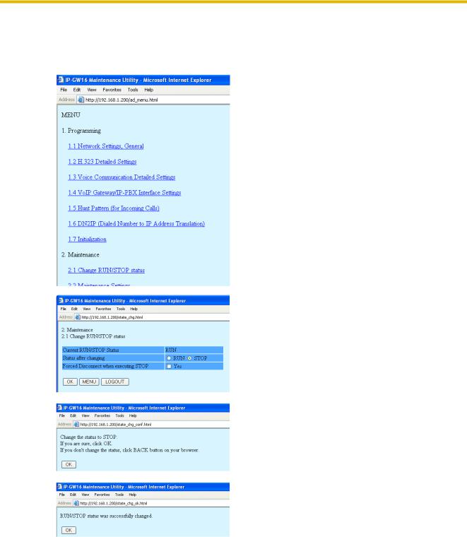
The main menu appears.
Note
For readability of the text on the screen, it is recommended that you adjust the text size of Internet Explorer to below medium.
Note
If you finish a programming session without logging out from the card (e.g., quitting Internet Explorer, or returning to the log-in screen with the "Back" button of Internet Explorer), you cannot log in again for the period of time specified by the parameter Programming Auto Disconnect Time (default: 10 min).
For the log-out procedure and Programming Auto Disconnect Time setting, refer to "2.5.2 Log Out" and "2.3.2 Maintenance Settings" of the VoIP Gateway Card Programming Guide, respectively.
26 Getting Started
3.2Programming the VoIP Gateway Card in the Los Angeles Office
3.2.2Changing the Status of the VoIP Gateway Card
When programming the VoIP Gateway Card, place the card in the "STOP" status.
1. Click 2.1 Change RUN/STOP status in the main menu.
2. a. Click STOP for Status after changing. b. Click OK.
3. Click OK.
4. Click OK.
Getting Started |
27 |
|
|

3.2 Programming the VoIP Gateway Card in the Los Angeles Office
3.2.3Assigning the IP Address
When programming the VoIP Gateway Card for the first time, a new IP address must be assigned. Once this is done and the card is on-line, it will be able to communicate with the other cards over the VoIP network.
The specific setting values are based on the table under "IP Addressing Information" in "1.2.2 Numbering Plan Example".
1. Click 1.1 Network Settings, General in the main menu.
2. a. In the IP Address box, type 200.45.11.35.
b. In the Subnet Mask box, type 255.255.255.0. c. In the Default Gateway box, type 200.45.11.1. d. Click OK.
3. Confirm your entry, and then click OK.
Note
For more details about IP address assignment, refer to "2.2.1 Network Parameters" of the VoIP Gateway Card Programming Guide.
28 Getting Started
3.2Programming the VoIP Gateway Card in the Los Angeles Office
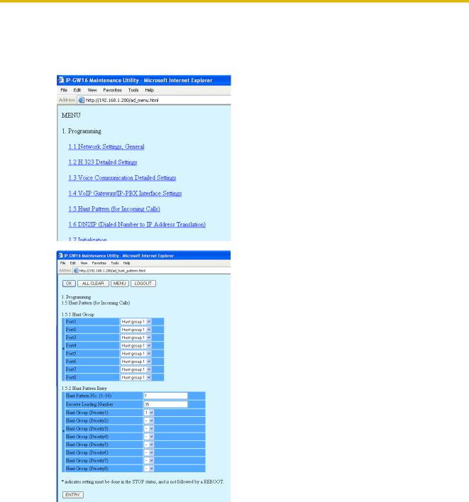
3.2.4Assigning the Hunt Pattern
The hunt pattern determines how to route incoming calls through the VoIP Gateway Card to the PBX.
1. Click 1.5 Hunt Pattern (for Incoming Calls) in the main menu.
2. a. In the Hunt Pattern No. box, type 1.
A hunt pattern will be created with this numbering.
b. In the Receive Leading Number box, type 35
(PBX code).
c. Click ENTRY. d. Click OK.
Getting Started |
29 |
|
|

3.2Programming the VoIP Gateway Card in the Los Angeles Office
3.Confirm your entry, and then click OK.
Note
For more details about hunt pattern assignment, refer to "2.2.5 Hunt Pattern Parameters" of the VoIP Gateway Card Programming Guide.
30 Getting Started
Loading...