


KX-TD1232
KX-TD816
Model
KX-TD1232
Digital Super Hybrid System
Installation Manual
D1232
DIGITAL SUPER HYBRID SYSTEM
Panasonic
Panasonic
D816
DIGITAL SUPER HYBRID SYSTEM
Please read this manual before connecting the Digital Super Hybrid System.

2 Installation Manual
Thank you for purchasing this Panasonic Model KX-TD816 / KX-TD1232, Digital
Super Hybrid System.

System Components
Installation Manual 3
System Components
System Components Table
Model Description
Service Unit KX-TD816
KX-TD1232
Digital Super Hybrid System (Main Unit)
Digital Super Hybrid System (Main Unit)
Telephone KX-T7420
KX-T7425
KX-T7431
KX-T7433
KX-T7436
KX-T7320
KX-T7335
KX-T7350
KX-T7220
KX-T7230
KX-T7235
KX-T7250
KX-T7130
KX-T7135
KX-T7020
KX-T7030
KX-T7050
KX-T7055
KX-T7051
KX-T7052
Digital proprietary telephone
Digital proprietary telephone
Digital proprietary telephone with 1-line display
Digital proprietary telephone with 3-line display
Digital proprietary telephone with 6-line display
Proprietary telephone
Proprietary telephone with backlit display
Proprietary telephone
Digital proprietary telephone
Digital proprietary telephone with 2-line display
Digital proprietary telephone with 6-line display
Digital proprietary telephone
Proprietary telephone with display
Proprietary telephone with backlit display
Proprietary telephone
Proprietary telephone with display
Proprietary telephone
Proprietary telephone
Single line telephone
Single line telephone

System Components
4 Installation Manual
Optional
Equipment
KX-T7440
KX-T7441
KX-T7240
KX-T7040
Digital DSS Console
Digital DSS Console
Digital DSS Console
DSS Console
KX-TD112
KX-TD160
KX-TD161
KX-TD170
KX-TD171
KX-TD180
KX-TD185
KX-TD187
*1
KX-TD191
*1
KX-TD192
*1
KX-TD193
KX-TD194
KX-TD196
*1
KX-TD197
*1
KX-TD198
*2
KX-TD284
KX-TD382
KX-TD384
KX-TD386
KX-TD290
*1
PLL Card
Doorphone Card (2 doorphone / 2 door opener)
Doorphone Card (4 doorphone / 4 door opener)
8-Station Line Unit
8-Station Line Unit with SLT CID
4-CO Line Unit
4-DID Line Unit
T1 Unit
DISA Card
System Inter Connection Card (two cards with Connection Cable)
Caller ID Card
SLT Message Waiting Lamp Adaptor Unit
Remote Card
High Speed Remote Card
High Speed Remote Unit
4-ISDN S / T-point Line Unit (4-ISDN Line Unit)
2-ISDN U-point Line Unit (2-ISDN Line Unit)
4-ISDN U-point Line Unit (4-ISDN Line Unit)
6-ISDN U-point Line Unit (6-ISDN Line Unit)
Primary Rate Interface ISDN Expansion Unit
KX-T30865
KX-T30890
Doorphone
Headset (Earphone type)
*
1
Can be installed in the KX-TD1232 only.
*
2
Can be installed in the KX-TD816 only.
System Components Table
Model Description

Important Safety Instructions
Installation Manual 5
Important Safety Instructions
When using your telephone equipment, basic safety precautions should always be followed to
reduce the risk of fire, electric shock and injury to persons, including the following:
a) Read and understand all instructions.
b) Follow all warnings and instructions marked on the product.
c) Unplug this product from the wall outlet before cleaning. Do not use liquid cleaners or
aerosol cleaners. Use a damp cloth for cleaning.
d) Do not use this product near water, for example, near a bathtub, wash bowl, kitchen sink,
or laundry tub, in a wet basement, or near a swimming pool.
e) Do not place this product on an unstable cart, stand, or table. The product may fall,
causing serious damage to the product.
f) Slots and openings in the cabinet and the back or bottom are provided for ventilation, to
protect it from overheating, these openings must not be blocked or covered. The
openings should never be blocked by placing the product on the bed, sofa, rug, or other
similar surface. This product should never be placed near or over a radiator or heat
register. This product should not be placed in a built-in installation unless proper
ventilation is provided.
g) This product should be operated only from the type of power source indicated on the
marking label. If you are not sure of the type of power supply to your home, consult your
dealer or local power company.
h) This product is equipped with a three wire grounding type plug, a plug having a third
(grounding) pin. This plug will only fit into a grounding type power outlet. This is a
safety feature. If you are unable to insert the plug into the outlet, contact your electrician
to replace your obsolete outlet. Do not defeat the safety purpose of the grounding type
plug.
i) Do not allow anything to rest on the power cord. Do not locate this product where the
cord will be abused by people walking on it.
j) Do not overload wall outlets and extension cords as this can result in the risk of fire or
electric shock.
k) Never push objects of any kind into this product through cabinet slots as they may touch
dangerous voltage points or short out parts that could result in a risk of fire or electric
shock. Never spill liquid of any kind on the product.
l) To reduce the risk of electric shock, do not disassemble this product, but take it to a
qualified serviceman when some service or repair work is required. Opening or
removing covers may expose you to dangerous voltages or other risks. Incorrect
reassembly can cause electric shock when the appliance is subsequently used.
m)Unplug this product from the wall outlet and refer servicing to qualified service
personnel under the following conditions:
1) When the power supply cord or plug is damaged or frayed.
2) If liquid has been spilled into the product.
3) If the product has been exposed to rain or water.

Important Safety Instructions
6 Installation Manual
4) If the product does not operate normally by following the operating instructions.
Adjust only those controls, that are covered by the operating instructions because
improper adjustment of other controls may result in damage and will often require
extensive work by a qualified technician to restore the product to normal operation.
5) If the product has been dropped or the cabinet has been damaged.
6) If the product exhibits a distinct change in performance.
n) Avoid using a telephone (other than a cordless type) during an electrical storm. There
may be a remote risk of electric shock from lightning.
o) Do not use the telephone to report a gas leak in the vicinity of the leak.
SAVE THESE INSTRUCTIONS

Attention
Installation Manual 7
Attention
• Keep the unit away from heating appliances and electrical noise generating devices such as
fluorescent lamps, motors and televisions. These noise sources can interfere with the
performance of the Digital Super Hybrid System.
• This unit should be kept free of dust, moisture, high temperature (more than 40°C / 104°F)
and vibration, and should not be exposed to direct sunlight.
• Never attempt to insert wires, pins, etc. into the vents or other holes of this unit.
• If there is any trouble, disconnect the unit from the telephone line. Plug the telephone
directly into the telephone line. If the telephone operates properly, do not reconnect the unit
to the line until the trouble has been repaired by an authorized Panasonic Factory Service
Center. If the telephone does not operate properly, chances are that the trouble is in the
telephone system, and not in the unit.
• Do not use benzine, thinner, or the like, or any abrasive powder to clean the cabinet. Wipe
it with a soft cloth.
WARNING
THIS UNIT MAY ONLY BE INSTALLED AND SERVICED BY QUALIFIED
SERVICE PERSONNEL.
WHEN A FAILURE OCCURS WHICH RESULTS IN THE INTERNAL PARTS
BECOMING ACCESSIBLE, DISCONNECT THE POWER SUPPLY CORD
IMMEDIATELY AND RETURN THIS UNIT TO YOUR DEALER.
DISCONNECT THE TELECOM CONNECTION BEFORE DISCONNECTING THE
POWER CONNECTION PRIOR TO RELOCATING THE EQUIPMENT, AND
RECONNECT THE POWER FIRST.
THIS UNIT IS EQUIPPED WITH AN EARTHING CONTACT PLUG. FOR SAFETY
REASONS THIS PLUG MUST ONLY BE CONNECTED TO AN EARTHING
CONTACT SOCKET WHICH HAS BEEN INSTALLED ACCORDING TO
REGULATIONS.
THE POWER SUPPLY CORD IS USED AS THE MAIN DISCONNECT DEVICE,
ENSURE THAT THE SOCKET-OUTLET IS LOCATED / INSTALLED NEAR THE
EQUIPMENT AND IS EASILY ACCESSIBLE.
TO PREVENT FIRE OR SHOCK HAZARD, DO NOT EXPOSE THIS PRODUCT TO
RAIN OR MOISTURE.
Attention
8 Installation Manual
Accessory Order Information
• Replacement parts and accessories are available through your local authorized parts
distributor.
• For ordering accessories, call toll free: 1-800-332-5368.
W:White B:Black
When you ship the product
Carefully pack and send it prepaid, adequately insured and preferably in the original carton.
Attach a postage-paid letter, detailing the symptom, to the outside of the carton. DO NOT send
the product to the Executive or Regional Sales offices. They are NOT equipped to make
repairs.
Product service
Panasonic Factory Servicenters for this product are listed in the servicenter directory. Consult
your authorized Panasonic dealer for detailed instructions.
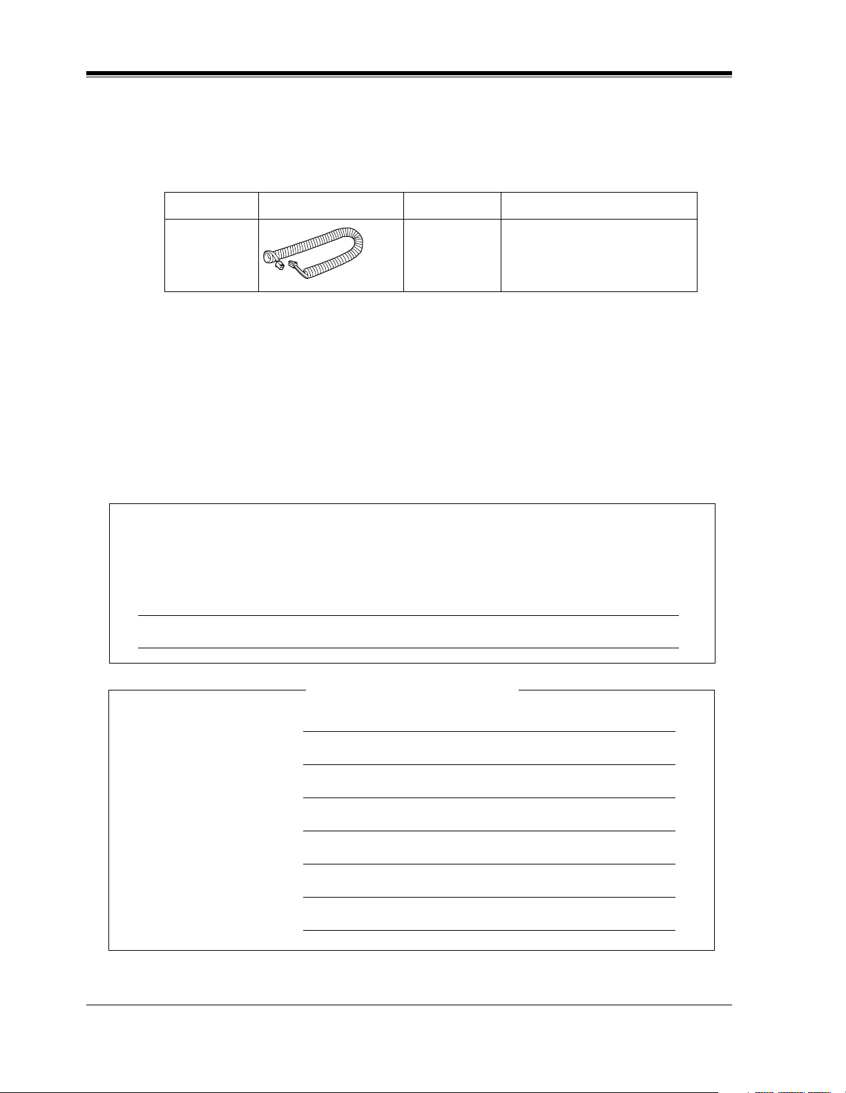
Part No. Picture Description Comment
KX-J07W/B
KX-J15W/B
KX-J25W/B
Handset cord
213.36 cm (7 feet)
457.2 cm (15 feet)
762 cm (25 feet)
The serial number of this product may be found on the label affixed to the bottom
of the unit. You should note the model number and the serial number of this unit in
the space provided and retain this book as a permanent record of your purchase to aid
in identification in the event of theft.
MODEL NO.:
SERIAL NO.:
DATE OF PURCHASE
NAME OF DEALER
DEALER’S ADDRESS
DEALER’S TEL NO.
For your future reference

Introduction
Installation Manual 9
Introduction
This Installation Manual provides technical information for the Panasonic Digital Super
Hybrid System, KX-TD816 / KX-TD1232. It is designed to serve as an overall technical
reference for the system and includes a description of the system, its hardware and software,
features and services and environmental requirements.
This manual contains the following sections:
Section 1, System Outline
Provides general information on the system including system capacity and specifications.
Section 2, General Installation
Contains the basic system installation and wiring instructions, as well as how to install the
optional cards and units.
Section 3, ISDN Installation
Contains the ISDN unit installation and wiring instructions.
Section 4, T1 Installation
Contains the T1 unit installation and wiring instructions.
Section 5, Troubleshooting
Provides information for system and telephone troubleshooting.
Section 6, Index
Provides the important words and phrases to help you access the required information easily.
Programming Guide References
The related and required programming titles described in the Programming Guide
are noted
for your reference.
Programming Guide reference is also shown in the sentences as follows.
Example: <SYS PRG [109]>
Explanation: Refer to system program [109] in the Programming Guide.
This helps you know the related and required programming easily for the contents of the
sentences.
Features Guide References
The related feature titles described in the Features Guide
are noted for your reference.
Terms used in this Installation Manual

Introduction
10 Installation Manual
Along with this Installation Manual, the following manuals are available to help you know the
available features, program and use the KX-TD816 / KX-TD1232 system.
Features Guide
Provides information about the system features.
Programming Guide
Provides system programming instructions.
User Manual
Provides operating instructions for the end users using proprietary telephones, single line
telephones, consoles.
About the other manuals

F.C.C REQUIREMENTS AND RELEVANT INFORMATION
Installation Manual 11
F.C.C REQUIREMENTS AND RELEVANT
INFORMATION
1. Notification to the Telephone Company
This equipment complies with Part 68 of the FCC rules and the requirements adopted by
the ACTA. On the bottom of this equipment is a label that contains, among other
information, a product identifier in the format US: XXXXX##XXXXX. If requested, this
number must be provided to the telephone company.
Installation must be performed by a qualified professional installer. If required, provide the
telephone company with the following technical information:
• Telephone numbers to which the system will be connected
• Make: Panasonic
• Model: KX-TD816 / KX-TD1232
• FCC Registration No.: found on the bottom of the unit
• Ringer Equivalence No.: 0.4B
• Facility Interface Code: 02LS2, 02RV2-T, 02IS5
• Service Order Code: 9.0F, AS.2, 6.0P
• Required Network Interface Jack: RJ11 / 14C, RJ49
2. Ringer Equivalence Number (REN)
The REN is used to determine the number of devices that may be connected to a telephone
line. Excessive RENs on a telephone line may result in the devices not ringing in response
to an incoming call. In most, but not all areas, the sum of RENs should not exceed five (5.0).
To be certain of the number of devices that may be connected to a line, as determined by
the total RENs, contact the local telephone company. The REN for this product is part of
the product identifier that has the format US: XXXXX##XXXXX. The digits represented
by ## are the REN without a decimal point (e.g., 03 is a REN of 0.3). For earlier products,
the REN is separately shown on the label.
3. Incidence of Harm to the Telephone Lines
If this equipment causes harm to the telephone network, the telephone company will notify
you in advance that temporary discontinuance of service may be required. But if advance
notice isn't practical, the telephone company will notify the customer as soon as possible.
Also, you will be advised of your right to file a complaint with the FCC if you believe it is
necessary.
4. Changes in Telephone Company Communications Facilities, Equipment, Operations
and Procedures
The telephone company may make changes in its facilities, equipment, operations or
procedures that could affect the operation of the equipment. If this happens the telephone
company will provide advance notice in order for you to make necessary modifications to
maintain uninterrupted service.

F.C.C REQUIREMENTS AND RELEVANT INFORMATION
12 Installation Manual
5. Trouble with This Equipment
If trouble is experienced with this equipment, for repair or warranty information, please see
the attached warranty, which includes the Servicenter Directory. If the equipment is causing
harm to the telephone network, the telephone company may request that you disconnect the
equipment until the problem is resolved.
6. Connection to Party Line
Connection to party line service is subject to state tariffs. Contact the state public utility
commission, public service commission or corporation commission for information.
Note
Allowing this equipment to be operated in such a manner as to not provide for proper answer
supervision is a violation of Part 68 of the FCC's rules.
Proper answer supervision is when:
This equipment returns answer supervision to the public switched telephone network (PSTN)
when DID calls are:
—Answered by the called station
—Answered by the attendant
—Routed to a recorded announcement that can be administered by the customer
premises equipment (CPE) user.
—Routed to a dial prompt
This equipment returns answer supervision on all DID calls forwarded to the PSTN
Permissible exceptions are:
—A call is unanswered
—A busy tone is received
—A reorder tone is received
This equipment has been tested and found to comply with the limits for a Class A digital
device, pursuant to Part 15 of the FCC Rules. These limits are designed to provide reasonable
protection against harmful interference when the equipment is operated in a commercial
environment. This equipment generates, uses, and can radiate radio frequency energy and, if
not installed and used in accordance with the instruction manual, may cause harmful
interference to radio communications. Operation of this equipment in a residential area is likely
to cause harmful interference in which case the user will be required to correct the interference
at his own expense.

F.C.C REQUIREMENTS AND RELEVANT INFORMATION
Installation Manual 13
CAUTION
Any changes or modifications not expressly approved by the party responsible for compliance
could void the user's authority to operate this device.
When programming emergency numbers and / or making test calls to emergency numbers:
1. Remain on the line and briefly explain to the dispatcher the reason for the call before
hanging up.
2. Perform such activities in the off-peak hours, such as early morning hours or late evenings.
WARNING
The software contained in the ARS and TRS features to allow user access to the network
must be upgraded to recognize newly established network area codes and exchange codes
as they are placed into service. Failure to upgrade the premises PBXs or peripheral
equipment to recognize the new codes as they are established will restrict the customer
and the customer's employees from gaining access to the network and to these codes.
KEEP THE SOFTWARE UP-TO-DATE WITH THE LATEST DATA.

Table of Contents
14 Installation Manual
Table of Contents
1 System Outline
1.1 System Highlights ........................................................................................................ 18
1.1.1 System Highlights ...................................................................................................... 18
1.2 Basic System Construction ......................................................................................... 21
1.2.1 Basic System Construction......................................................................................... 21
1.2.2 System Connection Diagram ...................................................................................... 22
1.3 Proprietary Telephones ............................................................................................... 26
1.3.1 Proprietary Telephones ............................................................................................... 26
1.4 Options.......................................................................................................................... 27
1.4.1 Options ....................................................................................................................... 27
1.4.2 Expansion Unit Combination ..................................................................................... 29
1.5 Specifications................................................................................................................ 31
1.5.1 General Description.................................................................................................... 31
1.5.2 Characteristics ............................................................................................................33
1.5.3 System Capacity ......................................................................................................... 34
2 General Installation
2.1 Before Installation ....................................................................................................... 36
2.1.1 Before Installation ...................................................................................................... 36
2.2 Installation of the Main Unit ...................................................................................... 38
2.2.1 Unpacking................................................................................................................... 38
2.2.2 Location of Interfaces................................................................................................. 39
2.2.3 Wall Mounting............................................................................................................ 41
2.2.4 Opening Front Cover .................................................................................................. 43
2.2.5 Frame Ground Connection ......................................................................................... 44
2.3 Connection.................................................................................................................... 45
2.3.1 Outside Line Connection ............................................................................................ 45
2.3.2 Extension Connection................................................................................................. 47
2.3.3 Telephone Connection................................................................................................ 54
2.3.4 EXtra Device Port (XDP) Connection ....................................................................... 59
2.3.5 Polarity Sensitive Telephone Connection................................................................... 60
2.3.6 External Pager (Paging Equipment) Connection........................................................ 62
2.3.7 External Music Source Connection ............................................................................ 64
2.3.8 Printer and PC Connection ......................................................................................... 66
2.3.9 Installation of Lightning Protectors............................................................................ 70
2.4 Installation of Optional Cards and Unit.................................................................... 73
2.4.1 Location of Optional Cards and Units........................................................................ 73
2.4.2 4-CO Line Unit Connection ....................................................................................... 78
2.4.3 8-Station Line Unit Connection.................................................................................. 79
2.4.4 8-Station Line Unit with SLT CID Connection.......................................................... 80
2.4.5 4-DID Line Unit Connection...................................................................................... 81
2.4.6 Installing Expansion Unit ........................................................................................... 82
2.4.7 DISA Card and Remote Card / Unit Installation........................................................ 90
2.4.8 Caller ID Card Installation ......................................................................................... 96
2.4.9 Doorphone and Door Opener Connection.................................................................. 99
2.4.10 SLT Message Waiting Lamp Adaptor Unit Connection..........................................110

Table of Contents
Installation Manual 15
2.4.11 System Connection..................................................................................................118
2.5 Auxiliary Connection for Power Failure Transfer ..................................................121
2.5.1 Auxiliary Connection for Power Failure Transfer.....................................................121
2.6 Closing the Front Cover.............................................................................................123
2.6.1 Closing the Front Cover ............................................................................................123
2.7 Starting the System for the First Time .....................................................................125
2.7.1 Starting the System for the First Time ......................................................................125
2.8 System Restart ............................................................................................................127
2.8.1 System Restart ...........................................................................................................127
2.9 System Data Clear ......................................................................................................128
2.9.1 System Data Clear .....................................................................................................128
3 ISDN Installation
3.1 ISDN Network Outline...............................................................................................130
3.1.1 Overview ...................................................................................................................130
3.2 ISDN Line Connection ...............................................................................................132
3.2.1 Location of the Units.................................................................................................132
3.2.2 Installation the Unit ...................................................................................................134
4 T1 Installation
4.1 T1 Line Outline...........................................................................................................142
4.1.1 Overview ...................................................................................................................142
4.2 T1 Line Installation ....................................................................................................144
4.2.1 Location of the Unit ..................................................................................................144
4.2.2 Installing the Unit......................................................................................................145
5 Troubleshooting
5.1 Troubleshooting ..........................................................................................................150
5.1.1 Installation .................................................................................................................150
5.1.2 Connection ................................................................................................................151
5.1.3 Operation ...................................................................................................................153
5.1.4 Using the Reset Button..............................................................................................154
6 Index ...............................................................................................157

Table of Contents
16 Installation Manual

System Outline
Installation Manual 17
Section 1
System Outline
This section provides general information on the
system, including system capacity and specifications.

System Outline
18 Installation Manual
1.1 System Highlights
1.1.1 System Highlights
System Maximum Capacity
Module Expansion
Expansion modules are used to increase the system capacity.
EXtra Device Port (XDP)
Each extension jack in the system supports the connection of a digital proprietary telephone /
DSS Console and a single line device. The two devices per jack have different extension
numbers and are treated as two completely different extensions.
Paralleled Telephone Connection
Every jack in the system also supports the parallel connection of a proprietary telephone and a
single line device. They share the same extension number and are considered by the system to
be one extension.
Super Hybrid System
This system supports the connection of digital and analog proprietary telephones, DSS
Consoles and single line devices such as single line telephones, fax machines, and data
terminals.
KX-TD816 KX-TD1232 KX-TD1232x2
Extension
PT&SLT 16 (32) 32 (64) 64 (128)
ISDN telephone
*1
*1
Installing BRI unit, PRI unit and T1 unit together is impossible.
4 BRI (8 ch) 6 BRI (12 ch) 12 BRI (24 ch)
T1 Extension
(OPX)
*1
02424
Outside
Line
Analog 8 12 24
Basic Rate
Interface (BRI)
*1
4 BRI (8 ch) 6 BRI (12 ch) 12 BRI (24 ch)
Primary Rate
Interface (PRI)
*1
0 1 PRI (23 ch) 1 PRI (23 ch)
T1 Lines
*1
02424

System Outline
Installation Manual 19
System Connection
*1
With the addition of the optional System Inter Connection Card, two Digital Super Hybrid
Systems can be connected together to expand the system to a maximum of 24 outside lines and
64 extensions. The two systems function as one, therefore, some functions such as paging and
music-on-hold are duplicated.
ISDN Line Service
The system can manage a call received from the ISDN line by point-to-point or point-to-multi-
point configuration. To use this service, an optional unit is required.
TIE Line Service
A TIE line is a privately leased communication line between two or more PBXs, which
provides cost effective communications between company at different locations. To use this
service, an optional unit is required.
T1 Line Service
A T1 line is at the bottom of the digital transmission hierarchy. The T1 line contains 24 voice
channels. Voice is digitized by Pulse Code Modulation. To use this service, an optional unit is
required.
Digital Proprietary Telephones (DPT)
The system supports four different models of digital proprietary telephones which cover the
range from a monitor set to a large display handsfree version.
Programming System
The system can be programmed from a proprietary telephone or from a personal computer.
Voice Mail Integration
The system supports Voice Processing Systems with in-band DTMF signaling as well as DPT
integration. The Panasonic Voice Processing System provides automated attendant, voice
mail, interview and custom services.
Automatic Route Selection (ARS)
Automatically selects the pre-programmed least expensive route for outgoing toll calls.
*1
Available for the KX-TD1232 only.

System Outline
20 Installation Manual
Caller ID
Allows the user to see the name or telephone number of a caller on the telephone display before
answering a call.
Trunk (Outside Line) Answer From Any Station (TAFAS)
Ringing occurs over the external paging system; the call can be answered from any station.
Remote Station Lock Control
Allows an operator to lock an extension so that outgoing calls cannot be made.
Uniform Call Distribution (UCD)
Allows incoming calls to be distributed uniformly to a specific group of extensions.
System Outline
Installation Manual 21
1.2 Basic System Construction
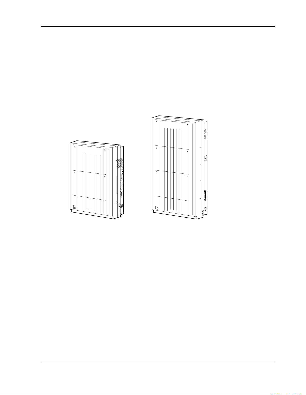
1.2.1 Basic System Construction
The KX-TD816 Digital Super Hybrid System has a basic capacity of four outside lines and
eight extensions, and the KX-TD1232 has eight outside lines and 16 extensions. They are
capable of supporting Panasonic digital and analog proprietary telephones, DSS Consoles and
single line devices such as single line telephones and fax machines.
To expand its capabilities, the system can be equipped with optional components or customer-
supplied peripherals such as external speakers and external music sources (e.g., radios).
D1232
DIGITAL SUPER HYBRID SYSTEM
Panasonic
Panasonic
D816
DIGITAL SUPER HYBRID SYSTEM
System Outline
22 Installation Manual
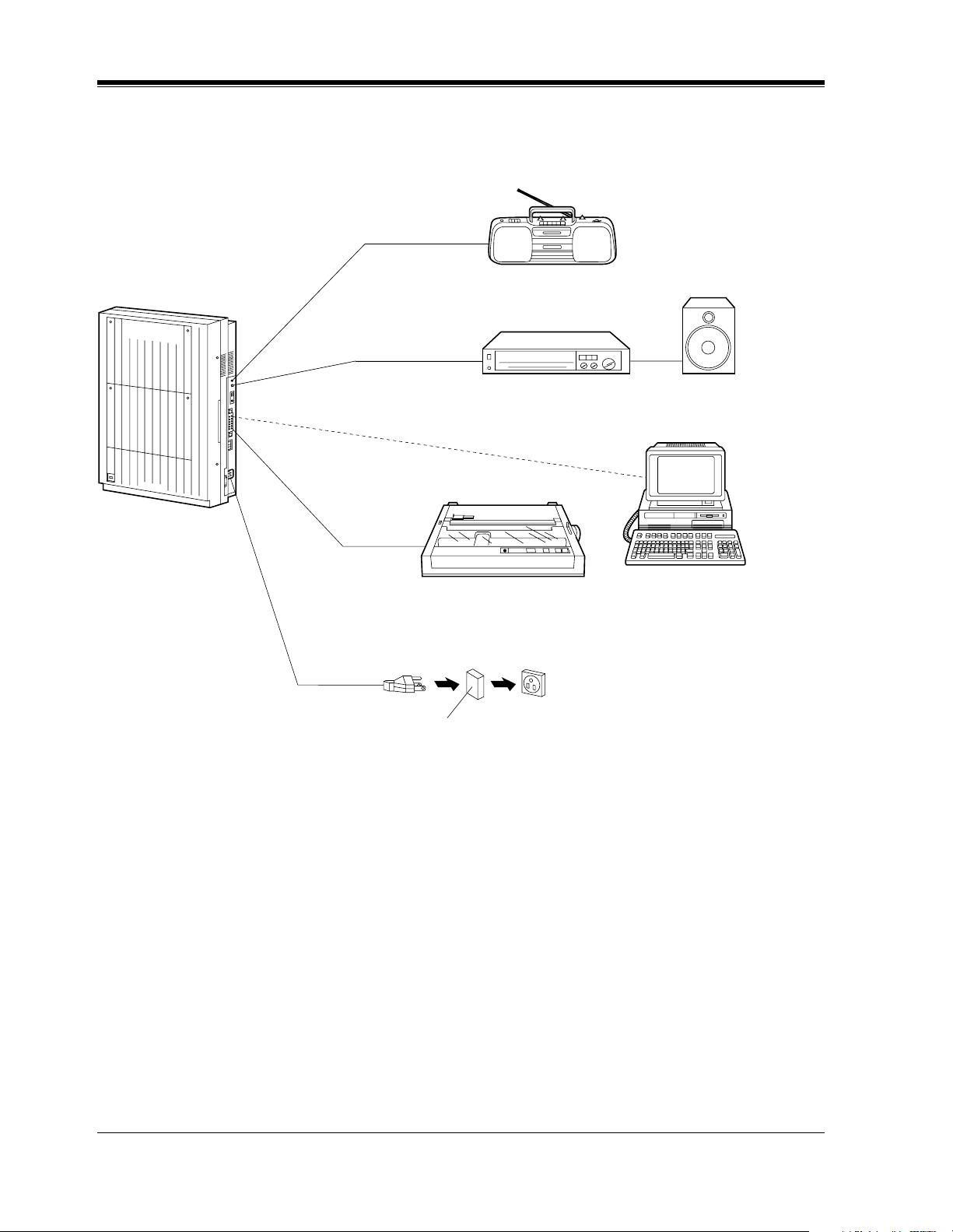
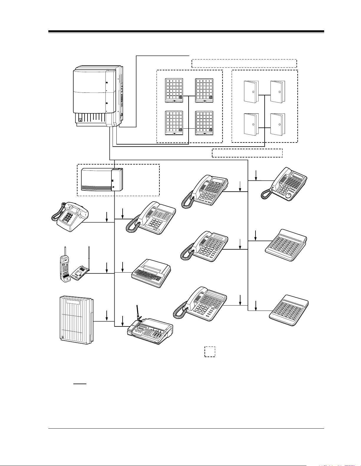
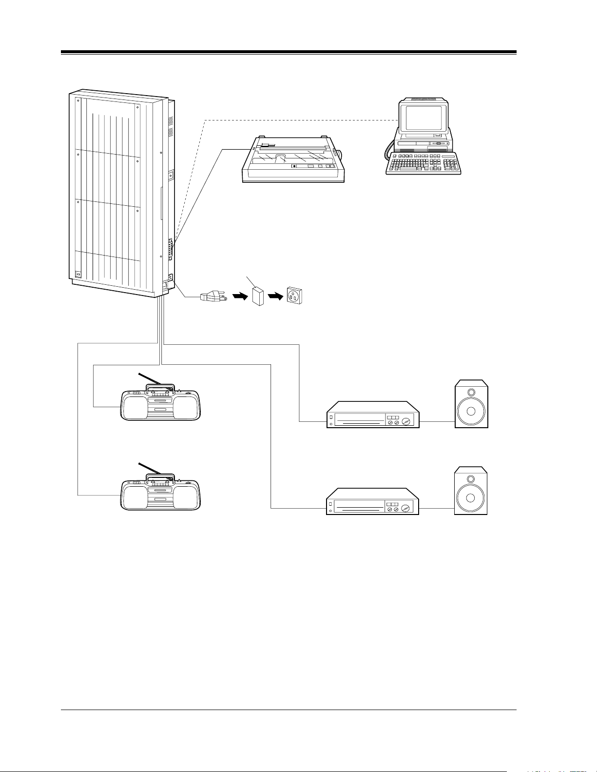
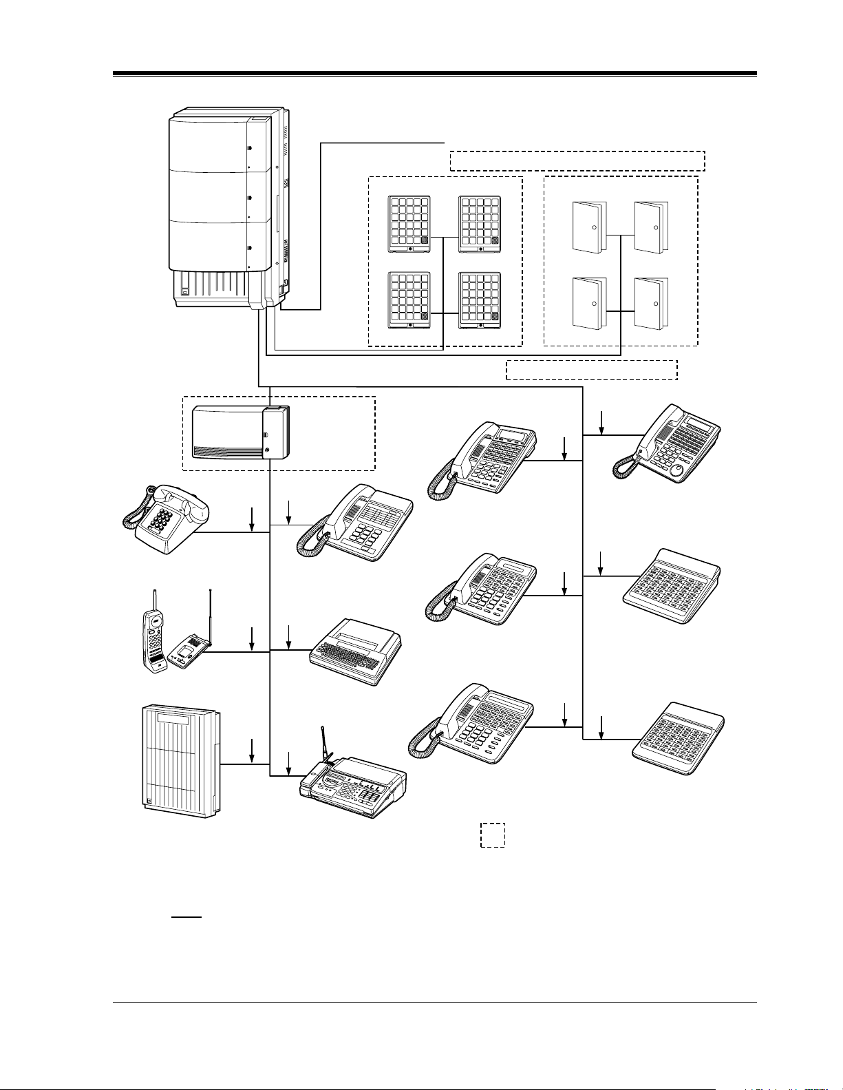
1.2.2 System Connection Diagram
KX-TD816
Panasonic
D816
DIGITAL SUPER HYBRID SYSTEM
Avoid using the same AC
outlet for office equipment
and the KX-TD816. Use a
dedicated AC outlet only.
External Music Source
Amplifier Speaker
Printer for SMDR or Personal Computer for System Programming
120 VAC, 60 Hz
AC Surge Protector
System Outline
Installation Manual 23
Note
• It is recommended that extension of jack 1 is a display proprietary telephone.
• Parallel connection of telephones is possible. Refer to the Parallel Telephone Connection in
2.3.3 Telephone Connection.
D816
DEGITAL SUPER HYBRID SYSTEM
Panasonic
KX-T7400 series digital
proprietary telephones
Digital DSS consoles
(KX-T7440 / KX-T7441
/ KX-T7240)
KX-T7200 series digital
proprietary telephones
KX-T7051 / KX-T7052
single line telephones
(two pair)
(one pair)
Data Terminal
Single Line Telephone
(Lightning Protectors)
to outside lines 1 through 4 (initial)
to outside lines 5 through 8 (additional)
8 Outside Lines
16 Extensions (8 extensions – initial, 8 extensions – additional)
Cordless Phone
(one pair)
(one pair)
KX-T7040 DSS console
(one pair)
(two
pair)
(one
pair)
(one
pair)
(one
pair)
(one
pair)
KX-T7000 series analog
proprietary telephones
(two
pair)
(two
pair)
KX-T7130 analog
proprietary telephone
Telephone Answering
Machine with Facsimile
Voice Processing System
SLT Message
Waiting Lamp
Adaptor Unit
KX-TD194
Panasonic
Panasonic
: needs Optional Cards or Adaptor.
Panasonic
Panasonic
Doorphone 1
Doorphone KX-T30865
Doorphone 2
Panasonic
Panasonic
Doorphone 3 Doorphone 4
Door Opener 1 Door Opener 2
Door Opener 3 Door Opener 4
System Outline
24 Installation Manual
KX-TD1232
D1232
DIGITAL SUPER HYBRID SYSTEM
Panasonic
Printer for SMDR or Personal Computer for System Programming
AC Surge Protector
120 VAC, 60 Hz
Avoid using the same AC
outlet for office equipment
and the KX-TD1232. Use a
dedicated AC outlet only.
External Music Source 1
External Music Source 2
Amplifier Speaker 1
Amplifier Speaker 2
System Outline
Installation Manual 25
Note
• It is recommended that extension of jack 1 is a display proprietary telephone.
• Parallel connection of telephones is possible. Refer to the Parallel Telephone Connection in
2.3.3 Telephone Connection.
Panasonic
Panasonic
Doorphone 1
Doorphone KX-T30865
Doorphone 2
Panasonic
Panasonic
Doorphone 3 Doorphone 4
Door Opener 1 Door Opener 2
Door Opener 3 Door Opener 4
: needs Optional Cards or Adaptor.
Panasonic
Panasonic
KX-T7400 series digital
proprietary telephones
Digital DSS consoles
(KX-T7440 / KX-T7441
/ KX-T7240)
KX-T7200 series digital
proprietary telephones
KX-T7051 / KX-T7052
single line telephones
(two pair)
(one pair)
Data Terminal
Single Line Telephone
(Lightning Protectors)
to outside lines 1 through 8 (initial)
to outside lines 9 through 12 (additional)
12 Outside Lines
32 Extensions (16 extensions – initial, 16 extensions – additional)
Cordless Phone
(one pair)
(one pair)
KX-T7040 DSS console
(one pair)
(two
pair)
(one
pair)
(one
pair)
(one
pair)
(one
pair)
KX-T7000 series analog
proprietary telephones
(two
pair)
(three
pair)
KX-T7130 analog
proprietary telephone
Telephone Answering
Machine with Facsimile
Voice Processing System
SLT Message
Waiting Lamp
Adaptor Unit
KX-TD194
D1232
DEGITAL SUPER HYBRID SYSTEM
Panasonic

System Outline
26 Installation Manual
1.3 Proprietary Telephones
1.3.1 Proprietary Telephones
The following Panasonic proprietary telephones are available with this system.
Note
Flexible CO : Flexible CO button (programmable)
PF : Programmable Feature button
Proprietary
Telephone
Description
KX-T7420 Digital, speakerphone, 12 Flexible CO
KX-T7425 Digital, speakerphone, 24 Flexible CO
KX-T7431 Digital, 1-line display, speakerphone, 12 Flexible CO
KX-T7433 Digital, 3-line display, speakerphone, 24 Flexible CO
KX-T7436 Digital, 6-line display, speakerphone, 24 Flexible CO
KX-T7320 Speakerphone, 12 Flexible CO
KX-T7335 1-line backlit display, speakerphone, 12 Flexible CO
KX-T7350 Monitor, 12 Flexible CO
KX-T7220 Digital, speakerphone, 24 Flexible CO
KX-T7230 Digital, 2-line display, speakerphone, 24 Flexible CO
KX-T7235 Digital, 6-line display, speakerphone, 12 Flexible CO
KX-T7250 Digital, monitor, 6 Flexible CO
KX-T7130 1-line display, speakerphone, 12 Flexible CO, 12 PF
KX-T7135 1-line backlit display, speakerphone, 12 Flexible CO, 12 PF
KX-T7020 Speakerphone, 12 Flexible CO, 4 PF
KX-T7030 1-line display, speakerphone, 12 Flexible CO, 4 PF
KX-T7050 Monitor, 12 Flexible CO, 4 PF
KX-T7055 Monitor, 3 Flexible CO, 3 PF

System Outline
Installation Manual 27
1.4 Options
1.4.1 Options
Model No. Model Name Description
Max.
Quantity
on
KX-
TD816
Max. Quantity on
KX-TD1232
Single
System
System
Connection
KX-TD170 8-Station Line Unit Adds 8 extension lines. 1 2 4
KX-TD171 8-Station Line Unit
with SLT CID
Adds 8 extension lines
which contain single
line telephones CID.
12 4
KX-TD180 4-CO Line Unit Adds 4 outside lines. 1 1 2
KX-TD185 4-DID Line Unit Adds 4 DID lines. 1 1 2
KX-TD187 T1 Unit Adds 1 T1 line. — 1 1
KX-TD382 2-ISDN Unit Adds 2 ISDN U-point
lines.
11 2
KX-TD384 4-ISDN Unit Adds 4 ISDN U-point
lines.
11 2
KX-TD386 6-ISDN Unit Adds 6 ISDN U-point
lines.
11 2
KX-TD284 4-ISDN Unit Adds 4 ISDN S / T-
point lines.
11 2
KX-TD290 Primary Rate
Interface ISDN
Expansion Unit
Adds 1 PRI ISDN line. — 1 1
KX-TD191 DISA Card Supports the Direct
Inward System Access
(DISA) feature and
records outgoing
messages.
—1 2
KX-TD192 System Inter
Connection Card
Connects two Digital
Super Hybrid Systems.
—— 2
KX-TD193 Caller ID Card Supports the Caller ID
Service of the central
office.
23 6

System Outline
28 Installation Manual
KX-TD194 SLT Message
Waiting Lamp
Adaptor Unit
Supports the Message
Waiting feature for a
single line telephone
with a message waiting
lamp. One unit supoorts
16 extensions.
12 4
KX-TD196 Remote Card Supports the
programming and
maintenance of the
system from a remote
location.
—1 2
KX-TD197 High Speed Remote
Card
Supports the
programming and
maintenance of the
system from a remote
location.
—1 2
KX-TD198 High Speed Remote
Unit
Supports the
programming and
maintenance of the
system from a remote
location.
1— —
KX-TD112 PLL Card Synchronizes the
system clock with the
clock of the ISDN
network.
11 1
(Master Only)
KX-TD160 Doorphone Card Supports 2 doorphones
and 2 door openers.
11 2
KX-TD161 Doorphone Card Supports 4 doorphones
and 4 door openers.
11 2
KX-T7440 /
KX-T7441 /
KX-T7240 /
KX-T7040 /
DSS Console Provides easy and quick
access to extensions
and features. This must
be used with a
proprietary telephone.
44 8
KX-T30865 Doorphone Used for a doorphone
call.
22 4
Model No. Model Name Description
Max.
Quantity
on
KX-
TD816
Max. Quantity on
KX-TD1232
Single
System
System
Connection

System Outline
Installation Manual 29
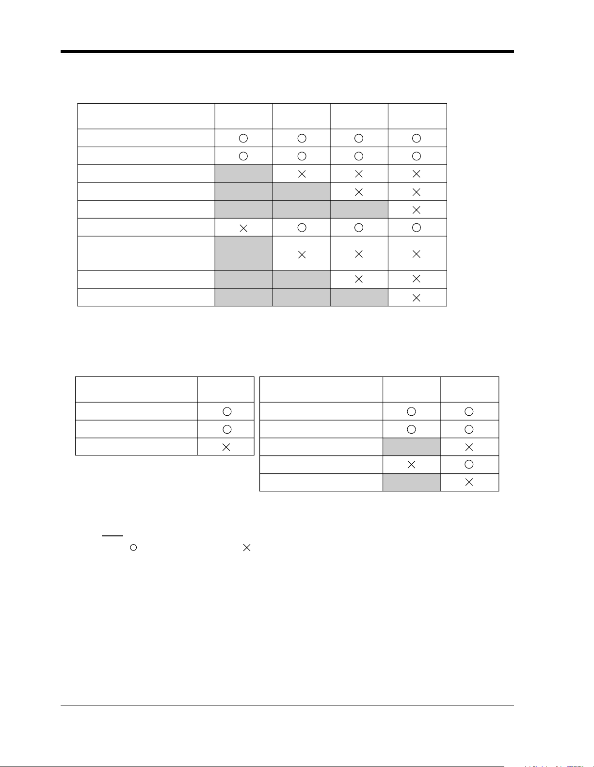
1.4.2 Expansion Unit Combination
KX-TD816
KX-TD1232 Master System
Basic (no unit connected)
+ KX-TD17x
+ KX-TD180 / KX-TD185
+ KX-TD284
+ KX-TD38x
KX-TD38xKX-TD284
KX-TD180
/
KX-TD185
KX-TD17x
Basic (no unit connected)
+ KX-TD17x
+ KX-TD180 / KX-TD185
+ KX-TD187
+ KX-TD284
+ KX-TD38x
+ KX-TD290
+ KX-TD17x + KX-TD17x
+ KX-TD17x + KX-TD180 /
KX-TD185
+ KX-TD17x + KX-TD187
+ KX-TD17x + KX-TD284
+ KX-TD17x + KX-TD38x
+ KX-TD17x + KX-TD290
KX-TD284KX-TD187KX-TD17x KX-TD38x KX-TD290
KX-TD180 /
KX-TD185
System Outline
30 Installation Manual
KX-TD1232 Slave System (KX-TD187 or KX-TD290 is not connected to the master
system)
KX-TD1232 Slave System (KX-TD187 or KX-TD290 is connected to the master system)
Note
• : Combination possible; : Combination not possible;
Shaded part: These combinations appear elsewhere in the table.
x: Any number (e.g., KX-TD17x can be KX-TD170 or KX-TD171)
• The KX-TD187 and KX-TD290 can only be connected to the master system.
• When the KX-TD187 or KX-TD290 is connected to the master system, Outside Line and
Basic Rate Interface (BRI) in the slave system do not work.
• * When KX-TD290 is connected to the master system, KX-TD284 is only used for ISDN
extension ports in the slave system. When KX-TD187 is connected to the master system,
KX-TD284 is not available to be connected to the slave system.
Basic (no unit connected)
+ KX-TD17x
+ KX-TD180 / KX-TD185
+ KX-TD284
+ KX-TD38x
+ KX-TD17x + KX-TD17x
+ KX-TD17x + KX-TD180 /
KX-TD185
+ KX-TD17x + KX-TD284
+ KX-TD17x + KX-TD38x
KX-TD38xKX-TD284KX-TD17x
KX-TD180
/
KX-TD185
Basic (no unit connected)
+ KX-TD17x
+ KX-TD17x + KX-TD17x
KX-TD17x
Basic (no unit connected)
+ KX-TD17x
+ KX-TD284
+ KX-TD17x + KX-TD17x
+ KX-TD17x + KX-TD284
KX-TD17x KX-TD284
*
<KX-TD290><KX-TD187>
 Loading...