


 Loading...
Advanced Hybrid System
Installation Manual
KX-TES824
Model KX-TEM824
Thank you for purchasing a Panasonic Advanced Hybrid System.
Please read this manual carefully before using this product and save this manual for future use.
KX-TES824/KX-TEM824: Version 2.0

System Components
System Components Table
|
|
|
Model |
|
|
|
Description |
|
|
|
|
|
|
|
|
|
|
Main Unit |
|
KX-TES824 |
|
Advanced Hybrid System: 3 to 8 Outside (CO) Lines, 8 to 24 |
||||
|
|
|
|
|
Extensions |
|
|
|
|
|
|
KX-TEM824 |
|
Advanced Hybrid System: 6 to 8 Outside (CO) Lines, 16 to |
|||
|
|
|
|
|
24 Extensions |
|
|
|
|
|
|
|
|
|
|
|
|
Optional Service Cards |
|
KX-TE82460 |
|
2-Port Doorphone Card |
|
|||
|
|
|
KX-TE82461 |
|
4-Port Doorphone Card |
|
||
|
|
|
KX-TE82474 |
|
8-Port SLT Extension Card |
|
||
|
|
|
KX-TE82480 |
|
2-Port Analogue CO Line and 8-Port SLT Extension Card |
|||
|
|
|
KX-TE82483 |
|
3-Port Analogue CO Line and 8-Port Hybrid Extension Card |
|||
|
|
|
KX-TE82491 |
|
Message Expansion Card for DISA/UCD OGMs |
|||
|
|
|
KX-TE82492 |
|
2-Channel Voice Message Card |
|
||
|
|
|
KX-TE82493 |
|
3-Port Caller ID Card |
|
|
|
|
|
|
|
|
|
|
|
|
Proprietary Equipment |
|
KX-T30865 |
|
Doorphone |
|
|
||
|
|
|
KX-A227 |
|
Backup Battery Cable |
|
|
|
|
|
|
|
|
|
|
|
|
Expandability of Outside (CO) Lines and Extensions |
|
|
||||||
|
|
|
|
|
|
|
|
|
|
|
KX-TE82483 |
|
KX-TE82480 |
|
KX-TE82474 |
|
|
|
Outside (CO) Line: 3 |
Outside (CO) Line: 2 |
|
Outside (CO) Line: 0 |
Expanded |
|||
|
|
System |
||||||
|
|
|
|
|
|
|
|
|
|
Extension: 8 |
Extension: 8 |
|
Extension: 8 |
|
|||
|
|
|
|
|
|
|
|
|
KX-TES824 |
|
|
– |
|
– |
|
0 |
3 |
Outside (CO) Line: 3 |
|
|
– |
|
– |
|
8 |
16 |
Extension: 8 |
|
|
|
|
|
|
|
|
|
|
– |
2 |
|
– |
5 |
||
|
|
|
|
|||||
|
|
|
– |
8 |
|
– |
16 |
|
|
|
|
|
|
|
|
|
|
|
|
3 |
|
– |
|
– |
6 |
|
|
|
8 |
|
– |
|
– |
16 |
|
|
|
|
|
|
|
|
|
|
|
|
3 |
|
– |
|
0 |
6 |
|
|
|
8 |
|
– |
|
8 |
24 |
|
|
|
|
|
|
|
|
||
|
|
3 |
2 |
|
– |
8 |
||
|
|
8 |
8 |
|
– |
24 |
||
|
|
|
|
|
|
|
|
|
2 Installation Manual

Expandability of Outside (CO) Lines and Extensions
|
KX-TE82483 |
KX-TE82480 |
KX-TE82474 |
|
|
|
Outside (CO) Line: 3 |
Outside (CO) Line: 2 |
Outside (CO) Line: 0 |
Expanded |
|
|
System |
||||
|
|
|
|
||
|
Extension: 8 |
Extension: 8 |
Extension: 8 |
|
|
|
|
|
|
|
|
KX-TEM824 |
– |
– |
0 |
6 |
|
Outside (CO) Line: 6 |
– |
– |
8 |
24 |
|
Extension: 16 |
|
|
|
|
|
– |
2 |
– |
8 |
||
|
|||||
|
– |
8 |
– |
24 |
|
|
|
|
|
|
Abbreviations in this manual
Proprietary Telephone: PT
Single Line Telephone: SLT
Direct Station Selection: DSS
Compatible Proprietary Telephones
•KX-T7700, KX-T7300, and KX-T7000 series PTs
•KX-T7710 SLT
•KX-T7740, KX-T7340, and KX-T7040 DSS Consoles
For the equipment that can be connected to the PBX, refer to "1.2.2 System Connection Diagram".
Notice
Certain models may not be available in your country/area.
Certain optional service cards, PTs, and features may not be available in your country/area. Consult your certified Panasonic dealer for more information.
Important Notice
Prior to connection of this product, please verify that the intended operating environment is supported.
Satisfactory performance cannot be guaranteed for the following:
–interoperability and compatibility with all devices and systems connected to this product
–proper operation and compatibility with services provided by telecommunications companies over connected networks
Installation Manual |
3 |
|
|

Important Safety Instructions
When using your telephone equipment, basic safety precautions should always be followed to reduce the risk of fire, electric shock and injury to persons, including the following:
1.Read and understand all instructions.
2.Follow all warnings and instructions marked on the product.
3.Unplug the product from the wall outlet before cleaning. Do not use liquid cleaners or aerosol cleaners. Clean with a damp cloth.
4.Do not use this product near water, for example, near a bathtub, wash bowl, kitchen sink, or laundry tub, in a wet basement, or near a swimming pool.
5.Do not place the product on an unstable surface, as a fall may cause serious internal damage.
6.Slots and openings in the front, back and bottom of the cabinet are provided for ventilation; to protect it from overheating, these openings must not be blocked or covered. The openings should never be blocked by placing the product on a bed, sofa, rug, or other similar surface while in use. The product should never be placed near or over a radiator or other heat source. This product should not be placed in a sealed environment unless proper ventilation is provided.
7.The product should only be connected to the type of electrical power supply specified on the product label. If you are not sure of the type of power supply to your home, consult your dealer or local power company.
8.For safety purposes this unit is equipped with an earthed plug. If you do not have an earthed outlet, please have one installed. Do not bypass this safety feature by tampering with the plug.
9.Do not allow anything to rest on the power cord. Do not locate this product where the power cord may be stepped on or tripped on.
10.To reduce the risk of fire or electric shock, do not overload wall outlets and extension cords.
11.Do not insert objects of any kind into this product through its slots and openings, as they may touch dangerous voltage points or short out parts that could result in a risk of fire or electric shock. Never spill liquid of any kind on or in the product.
12.To reduce the risk of electric shock, do not disassemble this product. Only qualified personnel should service this product. Opening or removing covers may expose you to dangerous voltages or other risks. Incorrect reassembly can cause electric shock.
13.Unplug this product from the wall outlet and have it serviced by qualified service personnel in the following cases:
a)When the power supply cord or plug is damaged or frayed.
b)If liquid has been spilled into the product.
c)If the product has been exposed to rain or water.
d)If the product does not operate according to the operating instructions. Adjust only the controls that are explained in the operating instructions. Improper adjustment of other controls may result in damage and may require service by a qualified technician to restore the product to normal operation.
e)If the product has been dropped or the cabinet has been damaged.
f)If product performance deteriorates.
14.Avoid using wired telephones during an electrical storm. There is a remote risk of electric shock from lightning.
15.Do not use a telephone in the vicinity of a gas leak to report the leak.
SAVE THESE INSTRUCTIONS
4 Installation Manual

Precautions
•Keep the unit away from heating appliances and devices that generate electrical noise such as fluorescent lamps, motors and televisions. These noise sources can interfere with the performance of the PBX.
•This unit should be kept free of dust, moisture, high temperature (more than 40 ˚C ) and vibration, and should not be exposed to direct sunlight.
•If you are having problems making calls to outside destinations, follow this procedure to test the outside (CO) lines:
1.Disconnect the PBX from all outside (CO) lines.
2.Connect known working single line telephones (SLTs) to those outside (CO) lines.
3.Make a call to an external destination using those SLTs.
If a call cannot be carried out correctly, there may be a problem with the outside (CO) line that the SLT is connected to. Contact your telephone company.
If all SLTs operate properly, there may be a problem with your PBX. Do not reconnect the PBX to the outside (CO) lines until it has been serviced by an authorised Panasonic Factory Service Centre.
•Wipe the unit with a soft cloth. Do not clean the unit with abrasive powders or with chemical agents such as benzene or thinner.
Information on Disposal for Users of Waste Electrical & Electronic Equipment (private households)
•This symbol on the products and/or accompanying documents means that used electrical and electronic products should not be mixed with general household waste. For proper treatment, recovery and recycling, please take these products to designated collection points, where they will be accepted on a free of charge basis. Alternatively, in some countries you may be able to return your products to your local retailer upon the purchase of an equivalent new product. Disposing of this product correctly will help to save valuable resources and prevent any potential negative effects on human health and the environment which could otherwise arise from inappropriate waste handling. Please contact your local authority for further details of your nearest designated collection point. Penalties may be applicable for incorrect disposal of this waste, in accordance with national legislation.
For business users in the European Union
•If you wish to discard electrical and electronic equipment, please contact your dealer or supplier for further information.
Information on Disposal in other Countries outside the European Union
•This symbol is only valid in the European Union. If you wish to discard this product, please contact your local authorities or dealer and ask for the correct method of disposal.
|
|
|
|
|
|
Installation Manual |
|
5 |
|
|
|
|
|
|
|
||
|
|
|
|
|
|
|
||
|
|
|
|
|
|
|
||
|
|
|
|
|
|
|
||
|
|
|
|
|
|
|
||
|
|
|
|
|
|
|
||
|
|
|
|
|
|
|
||
|
|
|
|
|
|
|
|
|

For users in Finland, Norway and Sweden only
•This unit may only be installed in a room or space with restricted access, and equipotential bonding must be applied. For information on earthing, refer to "2.2.5 Connecting Frame Earth".
For users in New Zealand only
•This equipment shall not be set to make automatic calls to the Telecom '111' Emergency Service.
•The grant of a Telepermit for any item of terminal equipment indicates only that Telecom has accepted that the item complies with minimum conditions for connection to its network. It indicates no endorsement of the product by Telecom, nor does it provide any sort of warranty. Above all, it provides no assurance that any item will work correctly in all respects with another item of Telepermitted equipment of a different make or model, nor does it imply that any product is compatible with all of Telecom's network services.
•This equipment is not capable, under all operating conditions, of correct operation at the higher speeds for which it is designed. Telecom will accept no responsibility should difficulties arise in such circumstances.
•Some parameters required for compliance with Telecom's Telepermit requirements are dependent on the equipment (PBX) associated with this modem. In order to operate within the limits for compliance with Telecom's Specifications, the associated PBX equipment shall be set to ensure that modem calls are answered between 3 and 30 seconds of receipt of ringing.
•IMPORTANT NOTICE
Under power failure conditions, the connected telephones may not operate. Please ensure that a separate telephone, not dependent on local power, is available for emergency use.
•APPLICABLE ONLY TO TELECOM CUSTOMERS WHO HAVE AUTOMATIC ACCESS TO OTHER CARRIERS FOR TOLL CALLS
When calling back a number from the Caller ID list, all numbers prefixed with "0 + AREA CODE" will be automatically forwarded to your toll carrier. This includes numbers in your local calling area. The zero + area code should either be removed when calling back local numbers, or check with your toll carrier that a charge will not be levied.
•All persons using this device for recording telephone conversations shall comply with New Zealand law. This requires that at least one party to the conversation is to be aware that it is being recorded. In addition, the principles enumerated in the Privacy Act 1993 shall be complied with in respect to the nature of the personal information collected, the purpose for its collection, how it is used, and what is disclosed to any other party.
For users in Australia only
•No External TRC Terminal is provided due to an Internal Link between PE and TRC.
For users in Taiwan only
•Lithium batteries can be found in the circuit boards of the main board and optional cards of the PBX.
Notes
•When disposing of any of the above products, all batteries must be removed. Follow the applicable laws, regulations, and guidelines in your country/area regarding disposal of batteries.
•When replacing a battery, use only the same battery type, or an equivalent recommended by the battery manufacturer.
Notice
Regarding removing or replacing a battery in the circuit board, consult your dealer.
6 Installation Manual

WARNING
•THIS UNIT MAY ONLY BE INSTALLED AND SERVICED BY QUALIFIED SERVICE PERSONNEL.
•IF DAMAGE TO THE UNIT EXPOSES ANY INTERNAL PARTS, DISCONNECT THE POWER SUPPLY CORD IMMEDIATELY AND RETURN THE UNIT TO YOUR DEALER.
•UNPLUG THIS UNIT FROM THE AC OUTLET IF IT EMITS SMOKE, AN ABNORMAL SMELL OR MAKES UNUSUAL NOISE. THESE CONDITIONS CAN CAUSE FIRE OR ELECTRIC SHOCK. CONFIRM THAT SMOKE HAS STOPPED AND CONTACT AN AUTHORISED PANASONIC FACTORY SERVICE CENTRE.
•WHEN RELOCATING THE EQUIPMENT, FIRST DISCONNECT THE TELECOM CONNECTION BEFORE DISCONNECTING THE POWER CONNECTION. WHEN THE UNIT IS INSTALLED IN THE NEW LOCATION, RECONNECT THE POWER FIRST, AND THEN RECONNECT THE TELECOM CONNECTION.
•TO PREVENT POSSIBLE FIRE OR ELECTRIC SHOCK, DO NOT EXPOSE THIS PRODUCT TO RAIN OR MOISTURE.
•THE POWER SUPPLY CORD IS USED AS THE MAIN DISCONNECT DEVICE. ENSURE THAT THE AC OUTLET IS LOCATED NEAR THE EQUIPMENT AND IS EASILY ACCESSIBLE.
CAUTION
DANGER OF EXPLOSION EXISTS IF A BATTERY IS INCORRECTLY REPLACED. REPLACE ONLY WITH THE SAME OR EQUIVALENT TYPE RECOMMENDED BY THE BATTERY MANUFACTURER. DISPOSE OF USED BATTERIES ACCORDING TO THE MANUFACTURER'S INSTRUCTIONS.
Installation Manual |
7 |
|
|

For Future Reference
Please print, record, and retain the following information for future reference.
Note
The serial number of this product can be found on the label affixed to the unit. You should record the model number and the serial number of this unit as a permanent record of your purchase to aid in identification in the event of theft.
MODEL NO.
SERIAL NO.
DATE OF PURCHASE
NAME OF DEALER
DEALER'S ADDRESS
DEALER'S TEL. NO.
The KX-TES824E, the KX-TES824NE, the KX-TES824GR, the KX-TES824CE/ KX-TEM824CE, and the KX-TES824PD/KX-TEM824PD are designed to interwork with the Analogue Public Switched Telephone Network (PSTN) of European countries.
Panasonic Communications Co., Ltd./Panasonic Communications Company (U.K.) Ltd. declares that this equipment is in compliance with the essential requirements and other relevant provisions of Radio & Telecommunications Terminal Equipment (R&TTE) Directive 1999/5/EC.
Declarations of Conformity for the relevant Panasonic products described in this manual are available for download by visiting:
http://www.doc.panasonic.de
Contact:
Panasonic Services Europe
a Division of Panasonic Marketing Europe GmbH
Panasonic Testing Centre
Winsbergring 15, 22525 Hamburg, Germany
8 Installation Manual

Introduction
About the Installation Manual
This Installation Manual is designed to serve as an overall technical reference for Panasonic Advanced Hybrid System, KX-TES824 and KX-TEM824. It explains how to install the hardware and programme this PBX using KX-TE Maintenance Console.
The Installation Manual is divided into the following sections:
Section 1 System Outline
Provides general information on the PBX, including the system capacity and specifications.
Section 2 Installation
Provides detailed instructions for installing the PBX, optional service cards, and peripheral equipment.
Section 3 Guide for KX-TE Maintenance Console
Explains how to install and use KX-TE Maintenance Console, a PC-based programming utility.
Section 4 Troubleshooting
Provides information on troubleshooting and restarting the PBX.
About the Other Manuals
The following manuals are also available:
Feature Guide
Explains what the PBX can do, as well as how to obtain the most of its many features and facilities.
User Manual
Describes how users can access commonly used features and functions with proprietary telephones (PTs), single line telephones (SLTs), and Direct Station Selection (DSS) Consoles.
Trademarks
•Microsoft and Windows are either registered trademarks or trademarks of Microsoft Corporation in the United States and/or other countries.
•Intel and Celeron are trademarks or registered trademarks of Intel Corporation or its subsidiaries in the United States and other countries.
•All other trademarks identified herein are the property of their respective owners.
•Screen shots reprinted with permission from Microsoft Corporation.
Installation Manual |
9 |
|
|

Precautions for Users in the United Kingdom
FOR YOUR SAFETY, PLEASE READ THE FOLLOWING TEXT CAREFULLY.
This appliance is supplied with a moulded three-pin mains plug for your safety and convenience. A 5 amp fuse is fitted in this plug. Should the fuse need to be replaced, please ensure that the replacement fuse has a rating of 5 amps and that it is approved by ASTA or BSI to BS1362.
Check for the ASTA mark  or the BSI mark
  on the body of the fuse.
If the plug contains a removable fuse cover, you must ensure that it is refitted when the fuse is replaced. If you lose the fuse cover, the plug must not be used until a replacement cover is obtained. A replacement fuse cover can be purchased from your local Panasonic dealer.
IF THE FITTED MOULDED PLUG IS UNSUITABLE FOR THE AC OUTLET IN YOUR PREMISES, THEN THE FUSE SHOULD BE REMOVED AND THE PLUG CUT OFF AND DISPOSED OF SAFELY. THERE IS A DANGER OF SEVERE ELECTRICAL SHOCK IF THE CUT-OFF PLUG IS INSERTED INTO ANY 13 AMP OUTLET.
If a new plug is to be fitted, please observe the wiring code as shown below. If in any doubt, please consult a qualified electrician.
WARNING
THIS APPLIANCE MUST BE EARTHED.
IMPORTANT: The wires in the mains lead are coloured as follows:
Green-and-yellow: Earth
Blue: Neutral
Brown: Live
As the colours of the wires in the mains lead of this apparatus may not correspond with the coloured markings identifying the terminals in your plug, proceed as follows.
The wire that is coloured GREEN-AND-YELLOW must be connected to the terminal in the plug that
is marked with the letter E or by the safety earth symbol  or coloured GREEN or GREEN-AND- YELLOW.
The wire that is coloured BLUE must be connected to the terminal that is marked with the letter N or coloured BLACK.
The wire that is coloured BROWN must be connected to the terminal that is marked with the letter L or coloured RED.
10 Installation Manual
How to replace the fuse: Open the fuse compartment with a screwdriver and replace the fuse and fuse cover.
The equipment must be connected to direct extension lines, and a payphone should not be connected as an extension.
999 and 112 can be dialled on the apparatus after accessing the Exchange line for the purpose of making outgoing calls to the BT emergency services.
During dialling, this apparatus may tinkle the bells of other telephones using the same line. This is not a fault and we advise you not to call Fault Repair Service.
Installation Manual |
11 |
|
|

Table of Contents
1 System Outline ..................................................................................... |
15 |
|
1.1 |
System Highlights........................................................................................................... |
16 |
1.1.1 |
System Highlights ............................................................................................................. |
16 |
1.2 |
Basic System Construction ........................................................................................... |
17 |
1.2.1 |
Main Unit ........................................................................................................................... |
17 |
1.2.2 |
System Connection Diagram ............................................................................................ |
18 |
1.3 |
Specifications.................................................................................................................. |
19 |
1.3.1 |
General Description .......................................................................................................... |
19 |
1.3.2 |
Characteristics .................................................................................................................. |
20 |
1.3.3 |
System Capacity ............................................................................................................... |
21 |
2 Installation............................................................................................. |
23 |
|
2.1 |
Before Installing .............................................................................................................. |
24 |
2.1.1 |
Before Installing ................................................................................................................ |
24 |
2.2 |
Installing the Advanced Hybrid System........................................................................ |
26 |
2.2.1 |
Unpacking ......................................................................................................................... |
26 |
2.2.2 |
Names and Locations ....................................................................................................... |
27 |
2.2.3 |
Opening/Closing Covers ................................................................................................... |
28 |
2.2.4 |
Securing Cords ................................................................................................................. |
30 |
2.2.5 |
Connecting Frame Earth ................................................................................................... |
32 |
2.2.6 |
Connecting Backup Batteries............................................................................................ |
33 |
2.2.7 |
Wall Mounting ................................................................................................................... |
35 |
2.2.8 |
Installing Surge Protector.................................................................................................. |
38 |
2.3 |
Installing Optional Service Cards.................................................................................. |
41 |
2.3.1 |
Location of Optional Service Cards .................................................................................. |
41 |
2.3.2 |
3-Port Analogue CO Line and 8-Port Hybrid Extension Card (KX-TE82483) ................... |
42 |
2.3.3 |
2-Port Analogue CO Line and 8-Port SLT Extension Card (KX-TE82480) ....................... |
44 |
2.3.4 |
8-Port SLT Extension Card (KX-TE82474)........................................................................ |
49 |
2.3.5 |
3-Port Caller ID Card (KX-TE82493)................................................................................. |
52 |
2.3.6 |
2-Port Doorphone Card (KX-TE82460)............................................................................. |
53 |
2.3.7 |
4-Port Doorphone Card (KX-TE82461)............................................................................. |
54 |
2.3.8 |
Message Expansion Card for DISA/UCD OGMs (KX-TE82491) ...................................... |
55 |
2.3.9 |
2-Channel Voice Message Card (KX-TE82492) ............................................................... |
57 |
2.4 |
Connecting Outside (CO) Lines..................................................................................... |
58 |
2.4.1 |
Connecting Outside (CO) Lines ........................................................................................ |
58 |
2.5 |
Connecting Extensions .................................................................................................. |
59 |
2.5.1 |
Connecting Extensions ..................................................................................................... |
59 |
2.5.2 |
Connecting Extensions in Parallel..................................................................................... |
61 |
2.6 |
Connecting Doorphones and Door Openers................................................................ |
62 |
2.6.1 |
Connecting Doorphones and Door Openers..................................................................... |
62 |
2.7 |
Connecting Doorbell or Door Chime............................................................................. |
68 |
2.7.1 |
Connecting Doorbell or Door Chime ................................................................................. |
68 |
2.8 |
Connecting Peripherals.................................................................................................. |
70 |
2.8.1 |
Connecting Peripherals..................................................................................................... |
70 |
2.9 |
Power Failure Connections ............................................................................................ |
74 |
2.9.1 |
Power Failure Connections ............................................................................................... |
74 |
2.10 |
Starting the Advanced Hybrid System.......................................................................... |
75 |
12 Installation Manual

2.10.1 Starting the Advanced Hybrid System.............................................................................. |
75 |
3 Guide for KX-TE Maintenance Console .............................................. |
77 |
|
3.1 |
Installing KX-TE Maintenance Console ........................................................................ |
78 |
3.1.1 |
Installing KX-TE Maintenance Console on a PC.............................................................. |
78 |
3.2 |
Connection...................................................................................................................... |
80 |
3.2.1 |
Connection ....................................................................................................................... |
80 |
3.2.2 |
Starting KX-TE Maintenance Console for the first time.................................................... |
83 |
3.2.3 |
Accessing PBX via Internal Modem ................................................................................. |
84 |
4 Troubleshooting .................................................................................... |
87 |
|
4.1 |
Troubleshooting ............................................................................................................. |
88 |
4.1.1 |
Installation ........................................................................................................................ |
88 |
4.1.2 |
Connection ....................................................................................................................... |
89 |
4.1.3 |
Operation.......................................................................................................................... |
90 |
4.1.4 |
System Restart................................................................................................................. |
91 |
4.1.5 |
System Reset with System Data Clear ............................................................................ |
92 |
5 Appendix................................................................................................ |
93 |
|
5.1 |
Revision History ............................................................................................................. |
94 |
5.1.1 |
Version 2.0........................................................................................................................ |
94 |
Index |
............................................................................................................ |
95 |
Installation Manual |
13 |
|
|

14 Installation Manual

Section 1
System Outline
This section provides general information on the PBX, including the system capacity and specifications.
Installation Manual |
15 |
|
|

1.1 System Highlights
1.1System Highlights
1.1.1System Highlights
Built-in Voice Message (BV) (Optional voice message card required)
Built-in Voice Message (BV) allows a caller to leave a voice message in a user's personal message area or the PBX's common message area.
Fixed Line SMS Terminal Support (Optional Caller ID card required)
The PBX can relay incoming calls from a Short Message Service (SMS) centre to specific single line telephones (SLTs) that support SMS. Fixed Line SMS is a service that allows text messages to be sent and received via Public Switched Telephone Network (PSTN) access. We recommend using SMS-enabled Panasonic SLTs.
Caller ID Display on SLT (Optional Caller ID card required)
The PBX can receive Caller ID information (telephone numbers and callers' names) from calls received on outside (CO) lines. This information can be shown on the displays of SLTs that support Caller ID as well as proprietary telephones (PTs) when receiving calls.
3-level Automated Attendant (AA)
3-level Automated Attendant (AA) service allows a caller to dial a single-digit number (Direct Inward System Access [DISA] AA number) following the guidance of 3-level DISA outgoing messages (OGMs), and be connected to the desired party automatically.
Call Charge Calculation
The PBX can automatically calculate the approximate cost of calls and limit telephone usage to a preprogrammed budget on each extension. This feature allows users to calculate the cost of a call based on time, the leading digits of a phone number and/or the outside (CO) line carrying the call.
Station Message Detail Recording (SMDR)
The PBX (with an optional message expansion card) can automatically log up to 10 000 incoming/ outgoing outside (CO) line calls and 10 000 outgoing outside (CO) line calls for each extension. It is possible to log the Date, Time, Dial number, Duration and Charge of each call. The call logs can be output via the Serial Interface (RS-232C) port to a PC, printer, etc.
PC Programming
System programming settings can be accessed using a PC and the Panasonic KX-TE Maintenance Console software as well as by using a PT.
The PBX software can be upgraded via the Serial Interface (RS-232C) port or USB port, using the KX-TE Maintenance Console software.
Quick Setup
Basic PBX parameters such as Automatic Configuration for Outside (CO) Line Type, Country Setting can be programmed the first time the PBX is accessed with a PC using the KX-TE Maintenance Console software.
Advanced Hybrid System
This PBX supports the connection of PTs, Direct Station Selection (DSS) Consoles and single line devices such as SLTs, fax machines, wireless telephones and data terminals.
16 Installation Manual

1.2 Basic System Construction
1.2Basic System Construction
1.2.1Main Unit
The KX-TES824 has a basic capacity of 3 outside (CO) lines and 8 extensions, and the KX-TEM824 has a basic capacity of 6 outside (CO) lines and 16 extensions. It is capable of supporting Panasonic proprietary telephones (PTs), and single line devices such as single line telephones (SLTs), fax machines and data terminals.
To expand its capabilities, the PBX can be equipped with optional components or user-supplied peripherals, such as door openers, external speakers, and an external audio source such as a radio or CD player.
Installation Manual |
17 |
|
|

1.2 Basic System Construction
1.2.2System Connection Diagram
Outside (CO) Line
Remote PC
Doorphone
Batteries |
|
|
PC |
Printer |
PC |
|
SLT |
Door Opener/Doorbell/
Door Chime
External audio source (radio, CD player, etc.)
Paging system (loudspeaker, amplifier and speaker, etc.)
PT
FAX/Telephone
Answering Machine
DSS Console
Wireless Phone
Voice Processing
System
•Connect a display-equipped proprietary telephone (PT) to extension jack 01, as this extension is automatically designated as the manager extension.
•A PT and a single line telephone (SLT) can be connected in parallel to a Hybrid Port. (→ 2.5.2 Connecting Extensions in Parallel)
18 Installation Manual

1.3 Specifications
1.3Specifications
1.3.1General Description
Control Bus |
|
Original bus (16-bit, 24 MHz) |
|
|
|
|
|
||
Switching |
|
Space Division CMOS Crosspoint Switch |
||
|
|
|
||
Power Input |
|
100 V AC to 240 V AC, 1.5 A to 0.75 A, 50 Hz/60 Hz |
||
|
|
|
|
|
External Battery |
|
+24 V DC (+12 V DC × 2) |
|
|
|
|
|||
Maximum Power Failure Tolerance |
300 ms (without using backup batteries) |
|||
|
|
|
||
Memory Backup Duration |
7 years |
|
||
|
|
|
|
|
Dialling |
Outside (CO) Line |
Pulse (10 pps, 20 pps) or Tone (DTMF) |
||
|
|
|
||
|
Extension |
Pulse (10 pps, 20 pps) or Tone (DTMF) |
||
|
|
|
|
|
Intercom Path |
|
4 |
|
|
|
|
|
|
|
Mode Conversion |
|
Pulse-DTMF |
|
|
|
|
|
|
|
Ring Frequency |
|
20 Hz/25 Hz (selectable) |
|
|
|
|
|
|
|
Operating |
Temperature |
0 ˚C to 40 ˚C |
|
|
Environment |
|
|
||
|
|
|
|
|
Humidity |
10 % to 90 % (non-condensing) |
|
||
|
|
|||
|
|
|
|
|
Conference Call Outside (CO) Line |
2 |
|
|
|
|
|
|
|
|
Music on Hold (MOH) |
|
1 port |
|
|
|
|
Selectable MOH: Internal/External/Tone |
||
|
|
|
|
|
Paging |
Internal |
1 |
|
|
|
|
|
|
|
|
External |
1 port |
|
|
|
|
|
|
|
Serial Interface Port |
RS-232C |
1 |
|
|
|
|
|
|
|
|
USB 1.1 |
1 |
|
|
|
|
|
|
|
Extension Connection Cable |
SLT |
|
1-pair wire (T, R) |
|
|
|
|
|
|
|
|
PT |
|
2-pair wire (T, R, H, L) |
|
|
|
|
|
|
|
DSS Console |
|
1-pair wire (H, L) |
|
|
|
|
|
Dimensions |
|
368 mm (W) × 284 mm (H) × 102 mm (D) |
||
|
|
|
||
Weight (when fully expanded) |
Approx. 3.5 kg |
|
||
|
|
|
|
|
Installation Manual |
19 |
|
|

1.3 Specifications
1.3.2Characteristics
Terminal Equipment Loop Limit |
PT |
40 Ω |
|
|
|
|
SLT |
600 Ω including set |
|
|
|
|
Doorphone |
20 Ω |
|
|
|
Minimum Leakage Resistance |
15 000 Ω minimum |
|
|
|
|
Maximum Number of Extension |
1 PT or SLT in standard connection |
|
Instruments per Line |
1 PT and 1 SLT in parallel connection |
|
|
|
|
Ring Voltage |
75 Vrms at 20 Hz/25 Hz depending on the ringing load |
|
|
|
|
Outside (CO) Line Loop Limit |
1600 Ω maximum |
|
|
|
|
Hookswitch Flash/Recall Timing |
24 ms–2032 ms |
|
Range |
|
|
|
|
|
Door Opener Current Limit |
30 V DC/30 V AC, 3 A maximum |
|
|
|
|
Paging Terminal Impedance |
600 Ω |
|
|
|
|
MOH Terminal Impedance |
10 000 Ω |
|
|
|
|
20 Installation Manual
1.3 Specifications
1.3.3System Capacity
System Capacity
|
|
KX-TES824 |
KX-TEM824 |
|
|
|
|
Basic System |
Outside (CO) lines |
3 |
6 |
|
|
|
|
|
Extensions |
8 |
16 |
|
|
|
|
Fully Expanded System |
Outside (CO) lines |
8 |
8 |
|
|
|
|
|
Extensions |
24 |
24 |
|
|
|
|
Maximum Cards and Terminal Equipment
Item |
KX-TES824 |
KX-TEM824 |
|
|
|
PT |
16 |
16 |
|
|
|
SLT |
24 |
24 |
|
|
|
3-Port Analogue CO Line and 8-Port Hybrid Extension Card |
1 |
— |
|
|
|
2-Port Analogue CO Line and 8-Port SLT Extension Card |
1 |
1 |
|
|
|
8-Port SLT Extension Card |
1 |
1 |
|
|
|
Message Expansion Card for DISA/UCD OGMs |
1 |
1 |
|
|
|
2-Port Doorphone Card |
1 |
1 |
|
|
|
4-Port Doorphone Card |
1 |
1 |
|
|
|
3-Port Caller ID Card |
3 |
3 |
|
|
|
2-Channel Voice Message Card |
1 |
1 |
|
|
|
Doorphone |
4 |
4 |
|
|
|
Door Opener |
4 |
4 |
|
|
|
Pager |
1 |
1 |
|
|
|
Music on Hold (MOH) |
1 |
1 |
|
|
|
DSS Console |
2 |
2 |
|
|
|
System Data
Item |
Max. Quantity |
|
|
Operator |
1 |
|
|
System Speed Dialling |
100 |
|
|
One-touch Dialling |
24 per extension (PT) |
|
|
Personal Speed Dialling |
10 per extension |
|
|
Call Park Area |
10 |
|
|
Absent Message |
6 |
|
|
Installation Manual |
21 |
|
|

1.3 Specifications
Item |
Max. Quantity |
|
|
Toll Restriction (TRS) COS |
5 |
|
|
Extension Group |
8 |
|
|
Message Waiting |
8 per extension |
|
|
Message for Built-in Voice Message |
125 messages (total 60 minutes) |
|
|
22 Installation Manual

Section 2
Installation
This section provides detailed instructions for installing the PBX, optional service cards, and peripheral equipment.
Installation Manual |
23 |
|
|

2.1 Before Installing
2.1Before Installing
2.1.1Before Installing
Please read the following notes concerning installation and connection before installing the PBX and terminal equipment.
Be sure to comply with all applicable laws, regulations, and guidelines.
Safety Installation Instructions
When installing telephone wiring, basic safety precautions should always be followed to reduce the risk of fire, electric shock and injury to persons, including the following:
1.Never install telephone wiring during a lightning storm.
2.Never install telephone jacks in wet locations unless the jack is specifically designed for wet locations.
3.Never touch uninsulated telephone wires or terminals unless the telephone line has been disconnected at the network interface.
4.Use caution when installing or modifying telephone lines.
Installation Precautions
This PBX is designed for wall mounting only, and should be installed in a location where it is accessible for inspections and maintenance.
To prevent malfunction, noise, or discolouration, avoid installing the PBX in the following locations:
1.In direct sunlight and hot, cold, or humid places. (Temperature range: 0 ˚C to 40 ˚C )
2.Areas where sulfuric gases may be present, such as near thermal springs.
3.Areas where shocks or vibrations are frequent or strong.
4.High-dust areas, or places the PBX may come into contact with water or oil.
5.Near devices that generate high frequencies, such as sewing machines or electric welders.
6.On or near computers, telexes, or other office equipment, as well as microwave ovens or air conditioners. (It is preferable not to install the PBX in the same room as the above equipment.)
7.Within 1.8 m of radios and televisions. (Both the PBX and Panasonic proprietary telephones [PTs] should be at least 1.8 m away from such devices.)
8.Locations where other objects will obstruct the area around the PBX. Be especially careful to leave at least 20 cm of space above and 10 cm to the sides of the PBX for ventilation.
Wiring Precautions
Be sure to follow these instructions when wiring the unit:
1.Do not run unshielded telephone cables near AC power cables, computer cables, AC power sources, etc. When running cables near other noise-generating devices or cables, use shielded telephone cables or shield the telephone cables with metal tubing.
2.If cables are run on the floor, use protectors to prevent the cables from being stepped on. Avoid running cables under carpets.
3.Avoid using the same AC outlet for computers, telexes, and other office equipment, as noise generated by such equipment may hamper system performance or interrupt the system.
24 Installation Manual
2.1 Before Installing
4.Use 2-pair telephone cables when connecting Panasonic PTs.
Use 1-pair telephone cables when connecting single line telephones (SLTs), data terminals, answering machines, computers, voice processing systems, etc.
5.Unplug the PBX from its power source when wiring, and plug the PBX back in only after all wiring is completed.
6.Mis-wiring may cause the PBX to operate improperly. Refer to Section 2, "Installation" when wiring the PBX.
7.If an extension does not operate properly, disconnect the telephone from the extension line and connect it again, or turn off the PBX using the power switch then turn it on again.
8.For safety purposes this unit is equipped with an earthed plug. If you do not have an earthed outlet, please have one installed. Do not bypass this safety feature by tampering with the plug.
9.Use twisted pair cable for outside (CO) line connection.
10.Outside (CO) lines should be installed with surge protectors. For details, refer to "2.4.1 Connecting Outside (CO) Lines", "2.2.8 Installing Surge Protector".
WARNING
Static-sensitive devices are used in this PBX. To protect printed circuit boards from static electricity, do not touch the connectors indicated below. To discharge static electricity from your body, touch ground or wear an earthing strap.
Side View
Warning: Static-sensitive connectors
Installation Manual |
25 |
|
|

2.2 Installing the Advanced Hybrid System
2.2Installing the Advanced Hybrid System
2.2.1 |
Unpacking |
|
|
The following items are included upon shipment. |
|
|
|
|
|
Main Unit |
1 |
|
|
|
|
AC Cord* |
1* |
|
|
|
|
CD-ROM, Documentation |
1 set |
|
|
|
|
Screw (Wall Mounting) |
3 |
|
|
|
|
Washer (Wall Mounting) |
3 |
|
|
|
|
Pager Connector |
1 |
|
|
|
|
Audio Source Connector |
1 |
|
|
|
|
Strap |
1 |
|
|
|
|
Rivet |
1 |
|
|
|
* The type of the AC cord may vary depending on the country/area of use.
More than one type of AC cord may be included for countries/areas in Central and South America.
26 Installation Manual
2.2 Installing the Advanced Hybrid System
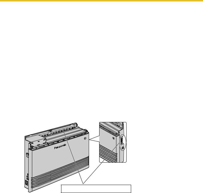
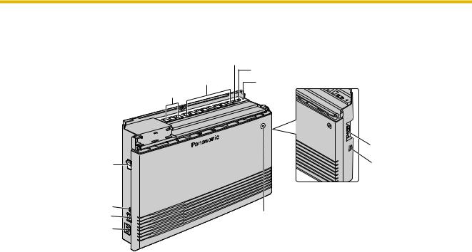
2.2.2Names and Locations
MOH Jack
Extension Modular Jacks
Outside (CO) Line Modular Jacks
Pager Jack |
Strap Hole |
|
RS-232C Port |
Power Switch |
USB Port |
|
Side View |
Battery Interface |
|
Protective Earth Terminal |
Run Indicator |
AC Inlet |
|
Installation Manual |
27 |
|
|
2.2 Installing the Advanced Hybrid System
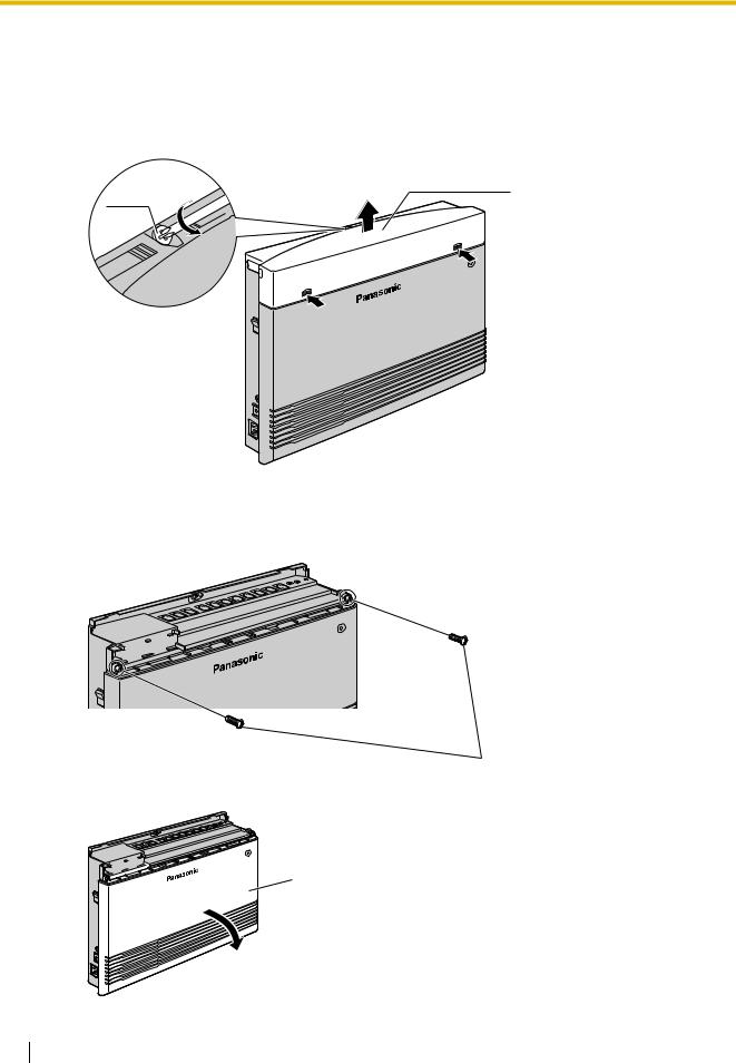
2.2.3Opening/Closing Covers
Opening Covers
1.Loosen the top cover screw.
2.Remove the top front cover.
Top front cover
Screw
Note
The screw cannot be removed from the cover.
3.Remove the 2 bottom-cover screws.
Screws
4.Open the bottom front cover.
Bottom front cover
28 Installation Manual
2.2 Installing the Advanced Hybrid System
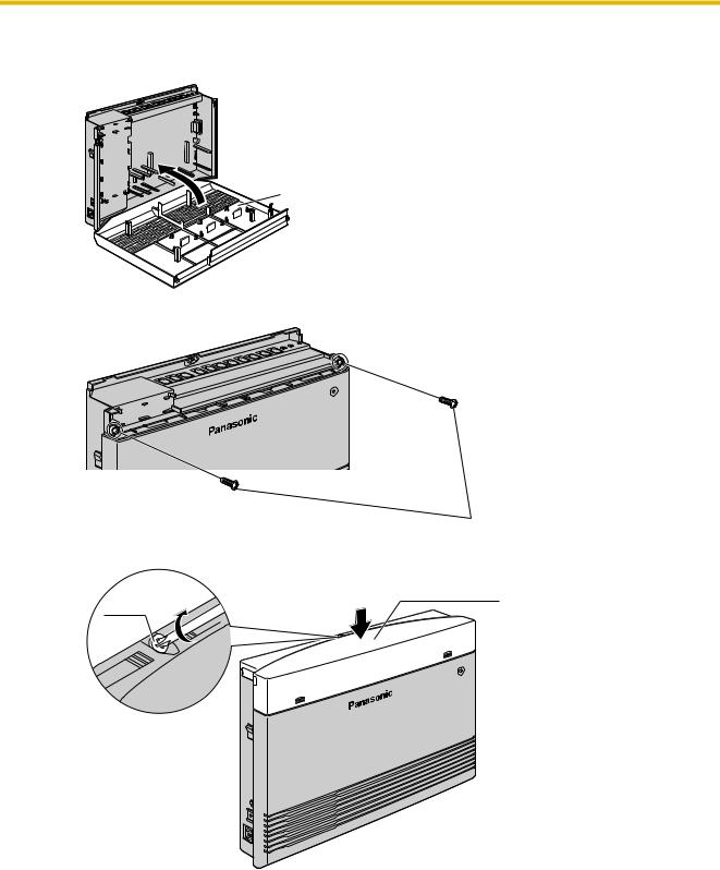
Closing Covers
1.Replace the bottom front cover.
Bottom front cover
2.Attach the 2 bottom-cover screws.
Screws
3.Replace the top front cover and tighten the screw.
Top front cover
Screw
Note
For safety reasons, keep the front covers closed while the PBX is in operation.
CAUTION
Tighten the above screw firmly to prevent the main unit from falling when the PBX is carried.
Installation Manual |
29 |
|
|
2.2 Installing the Advanced Hybrid System
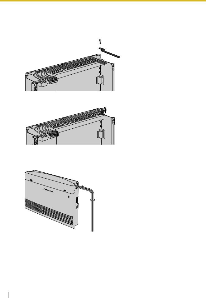
2.2.4Securing Cords
1.Insert the rivet into the hole in the strap.
2.Insert the rivet and strap into the hole on the PBX.
Rivet 

3.Wrap the strap around all of the cords.
4.Close the covers. (→ 2.2.3 Opening/Closing Covers)
5.Tie together all of the connected cords and secure them to the wall so that they cannot be pulled out of the PBX.
30 Installation Manual
Loading...