


KX-TEA308
Table of contents
 Loading...
Thank you for purchasing a Panasonic Advanced Hybrid System.
Please read this manual carefully before using this product and save this manual for future use.
KX-TEA308
Model
KX-TEB308
Advanced Hybrid System
Getting Started
2 Getting Started
System Components
System Components Table
Model Description
Main Unit KX-TEA308 Advanced Hybrid System: 3 Outside (CO) Lines, 8 Hybrid
Extensions
KX-TEB308 Advanced Hybrid System: 3 Outside (CO) Lines, 4 Hybrid
and 4 SLT Extensions
*1
*1
Taiwan: 4 PT Extensions
For supported extension types, refer to "2.3 Connecting Extensions".
Optional Service Cards KX-TE82460 2-Port Doorphone Card
KX-TE82492 2-Channel Voice Message Card (for KX-TEA308 only)
KX-TE82493 3-Port Caller ID Card
Proprietary Equipment KX-T30865 Doorphone
KX-A227 Backup Battery Cable
Notice
Certain models may not be available in your country/area.

Getting Started 3
Important Safety Instructions
When using your telephone equipment, basic safety precautions should always be followed to reduce
the risk of fire, electric shock and injury to persons, including the following:
1. Read and understand all instructions.
2. Follow all warnings and instructions marked on the product.
3. Unplug the product from the wall outlet before cleaning. Do not use liquid cleaners or aerosol
cleaners. Clean with a damp cloth.
4. Do not use this product near water, for example, near a bathtub, wash bowl, kitchen sink, or
laundry tub, in a wet basement, or near a swimming pool.
5. Do not place the product on an unstable surface, as a fall may cause serious internal damage.
6. Slots and openings in the front, back and bottom of the cabinet are provided for ventilation; to
protect it from overheating, these openings must not be blocked or covered. The openings should
never be blocked by placing the product on a bed, sofa, rug, or other similar surface while in use.
The product should never be placed near or over a radiator or other heat source. This product
should not be placed in a sealed environment unless proper ventilation is provided.
7. The product should only be connected to the type of electrical power supply specified on the
product label. If you are not sure of the type of power supply to your home, consult your dealer
or local power company.
8. For safety purposes this unit is equipped with an earthed plug. If you do not have an earthed
outlet, please have one installed. Do not bypass this safety feature by tampering with the plug.
9. Do not allow anything to rest on the power cord. Do not locate this product where the power cord
may be stepped on or tripped on.
10. To reduce the risk of fire or electric shock, do not overload wall outlets and extension cords.
11. Do not insert objects of any kind into this product through its slots and openings, as they may
touch dangerous voltage points or short out parts that could result in a risk of fire or electric
shock. Never spill liquid of any kind on or in the product.
12. To reduce the risk of electric shock, do not disassemble this product. Only qualified personnel
should service this product. Opening or removing covers may expose you to dangerous voltages
or other risks. Incorrect reassembly can cause electric shock.
13. Unplug this product from the wall outlet and have it serviced by qualified service personnel in the
following cases:
a) When the power supply cord or plug is damaged or frayed.
b) If liquid has been spilled into the product.
c) If the product has been exposed to rain or water.
d) If the product does not operate according to the operating instructions. Adjust only the
controls that are explained in the operating instructions. Improper adjustment of other
controls may result in damage and may require service by a qualified technician to restore
the product to normal operation.
e) If the product has been dropped or the cabinet has been damaged.
f) If product performance deteriorates.
14. Avoid using wired telephones during an electrical storm. There is a remote risk of electric shock
from lightning.
15. Do not use a telephone in the vicinity of a gas leak to report the leak.

4 Getting Started
16. Keep the unit away from heating appliances and devices that generate electrical noise such as
fluorescent lamps, motors and televisions. These noise sources can interfere with the
performance of the PBX.
17. This unit should be kept free of dust, moisture, high temperature (more than 40 ) and
vibration, and should not be exposed to direct sunlight.
18. If you are having problems making calls to outside destinations, follow this procedure to test the
outside (CO) lines:
1. Disconnect the PBX from all outside (CO) lines.
2. Connect known working single line telephones (SLTs) to those outside (CO) lines.
3. Make a call to an external destination using those SLTs.
If a call cannot be carried out correctly, there may be a problem with the outside (CO) line that
the SLT is connected to. Contact your telephone company.
If all SLTs operate properly, there may be a problem with your PBX. Do not reconnect the PBX
to the outside (CO) lines until it has been serviced by an authorised Panasonic Factory Service
Centre.
19. Wipe the unit with a soft cloth. Do not clean the unit with abrasive powders or with chemical
agents such as benzene or thinner.
For users in New Zealand only
• This equipment shall not be set to make automatic calls to the Telecom '111' Emergency Service.
• The grant of a Telepermit for any item of terminal equipment indicates only that Telecom has
accepted that the item complies with minimum conditions for connection to its network. It
indicates no endorsement of the product by Telecom, nor does it provide any sort of warranty.
Above all, it provides no assurance that any item will work correctly in all respects with another
item of Telepermitted equipment of a different make or model, nor does it imply that any product
is compatible with all of Telecom's network services.
• This equipment is not capable, under all operating conditions, of correct operation at the higher
speeds for which it is designed. Telecom will accept no responsibility should difficulties arise in
such circumstances.
• Some parameters required for compliance with Telecom's Telepermit requirements are
dependent on the equipment (PBX) associated with this modem. In order to operate within the
limits for compliance with Telecom's Specifications, the associated PBX equipment shall be set
to ensure that modem calls are answered between 3 and 30 seconds of receipt of ringing.
• IMPORTANT NOTICE
Under power failure conditions, the connected telephones may not operate. Please ensure that
a separate telephone, not dependent on local power, is available for emergency use.
For users in Australia only
• No External TRC Terminal is provided due to an Internal Link between PE and TRC.
For users in Taiwan only
• Lithium batteries can be found in the circuit boards of the main board and optional cards of the
PBX.
Notes
• When disposing of any of the above products, all batteries must be removed. Follow the
applicable laws, regulations, and guidelines in your country/area regarding disposal of
batteries.
• When replacing a battery, use only the same battery type, or an equivalent recommended
by the battery manufacturer.
˚C

Getting Started 5
Notice
Regarding removing or replacing a battery in the circuit board, consult your dealer.
For users in Finland, Norway and Sweden only
• This unit may only be installed in a room or space with restricted access, and equipotential
bonding must be applied. For information on earthing, refer to "
2.7 Connecting Frame Earth".
WARNING
• THIS UNIT MAY ONLY BE INSTALLED AND SERVICED BY QUALIFIED
SERVICE PERSONNEL.
• IF DAMAGE TO THE UNIT EXPOSES ANY INTERNAL PARTS, DISCONNECT
THE POWER SUPPLY CORD IMMEDIATELY AND RETURN THE UNIT TO YOUR
DEALER.
• UNPLUG THIS UNIT FROM THE AC OUTLET IF IT EMITS SMOKE, AN
ABNORMAL SMELL OR MAKES UNUSUAL NOISE. THESE CONDITIONS CAN
CAUSE FIRE OR ELECTRIC SHOCK. CONFIRM THAT SMOKE HAS STOPPED
AND CONTACT AN AUTHORISED PANASONIC FACTORY SERVICE CENTRE.
• WHEN RELOCATING THE EQUIPMENT, FIRST DISCONNECT THE TELECOM
CONNECTION BEFORE DISCONNECTING THE POWER CONNECTION. WHEN
THE UNIT IS INSTALLED IN THE NEW LOCATION, RECONNECT THE POWER
FIRST, AND THEN RECONNECT THE TELECOM CONNECTION.
• TO PREVENT POSSIBLE FIRE OR ELECTRIC SHOCK, DO NOT EXPOSE THIS
PRODUCT TO RAIN OR MOISTURE.
• THE POWER SUPPLY CORD IS USED AS THE MAIN DISCONNECT DEVICE.
ENSURE THAT THE AC OUTLET IS LOCATED NEAR THE EQUIPMENT AND IS
EASILY ACCESSIBLE.
CAUTION
DANGER OF EXPLOSION EXISTS IF A BATTERY IS INCORRECTLY REPLACED. REPLACE
ONLY WITH THE SAME OR EQUIVALENT TYPE RECOMMENDED BY THE BATTERY
MANUFACTURER. DISPOSE OF USED BATTERIES ACCORDING TO THE
MANUFACTURER'S INSTRUCTIONS.
SAVE THESE INSTRUCTIONS

6 Getting Started
Precautions for Users in the United Kingdom
FOR YOUR SAFETY, PLEASE READ THE FOLLOWING TEXT CAREFULLY.
This appliance is supplied with a moulded three-pin mains plug for your safety and convenience. A 5
amp fuse is fitted in this plug. Should the fuse need to be replaced, please ensure that the
replacement fuse has a rating of 5 amps and that it is approved by ASTA or BSI to BS1362.
Check for the ASTA mark or the BSI mark on the body of the fuse.
If the plug contains a removable fuse cover, you must ensure that it is refitted when the fuse is
replaced. If you lose the fuse cover, the plug must not be used until a replacement cover is obtained.
A replacement fuse cover can be purchased from your local Panasonic dealer.
IF THE FITTED MOULDED PLUG IS UNSUITABLE FOR THE AC OUTLET IN YOUR PREMISES,
THEN THE FUSE SHOULD BE REMOVED AND THE PLUG CUT OFF AND DISPOSED OF
SAFELY. THERE IS A DANGER OF SEVERE ELECTRICAL SHOCK IF THE CUT-OFF PLUG IS
INSERTED INTO ANY 13 AMP OUTLET.
If a new plug is to be fitted, please observe the wiring code as shown below. If in any doubt, please
consult a qualified electrician.
WARNING
THIS APPLIANCE MUST BE EARTHED.
IMPORTANT: The wires in the mains lead are coloured as follows:
Green-and-yellow: Earth
Blue: Neutral
Brown: Live
As the colours of the wires in the mains lead of this apparatus may not correspond with the coloured
markings identifying the terminals in your plug, proceed as follows.
The wire that is coloured GREEN-AND-YELLOW must be connected to the terminal in the plug that
is marked with the letter E or by the safety earth symbol
or coloured GREEN or GREEN-AND-
YELLOW.
The wire that is coloured BLUE must be connected to the terminal that is marked with the letter N or
coloured BLACK.
The wire that is coloured BROWN must be connected to the terminal that is marked with the letter L
or coloured RED.

Getting Started 7
How to replace the fuse: Open the fuse compartment with a screwdriver and replace the fuse and
fuse cover.
The equipment must be connected to direct extension lines, and a payphone should not be connected
as an extension.
999 and 112 can be dialled on the apparatus after accessing the Exchange line for the purpose of
making outgoing calls to the BT emergency services.
During dialling, this apparatus may tinkle the bells of other telephones using the same line. This is not
a fault and we advise you not to call Fault Repair Service.

8 Getting Started
Table of Contents
1 Before Installation .................................................................................. 9
1.1 Unpacking..........................................................................................................................9
1.2 System Connection Diagram .........................................................................................10
2 Installation............................................................................................. 11
2.1 Opening Covers ..............................................................................................................11
2.2 Connecting Outside (CO) Lines.....................................................................................11
2.3 Connecting Extensions ..................................................................................................12
2.4 Securing the Cables........................................................................................................13
2.5 Closing Covers................................................................................................................ 14
2.6 Wall Mounting..................................................................................................................15
2.6.1 Mounting on a Wooden Wall .............................................................................................15
2.6.2 Mounting on a Concrete or Mortar Wall ............................................................................16
2.7 Connecting Frame Earth ................................................................................................17
3 Starting the Advanced Hybrid System ............................................... 19
3.1 Starting the Advanced Hybrid System..........................................................................19
4 PC Programming .................................................................................. 21
4.1 PC Programming.............................................................................................................21
5 PT Programming................................................................................... 22
5.1 Programming Instructions .............................................................................................22
5.2 Programming Procedures..............................................................................................23
5.2.1 Basic Features .................................................................................................................. 26
5.2.2 Toll Restriction (TRS) Features .........................................................................................30
Getting Started 9
1 Before Installation
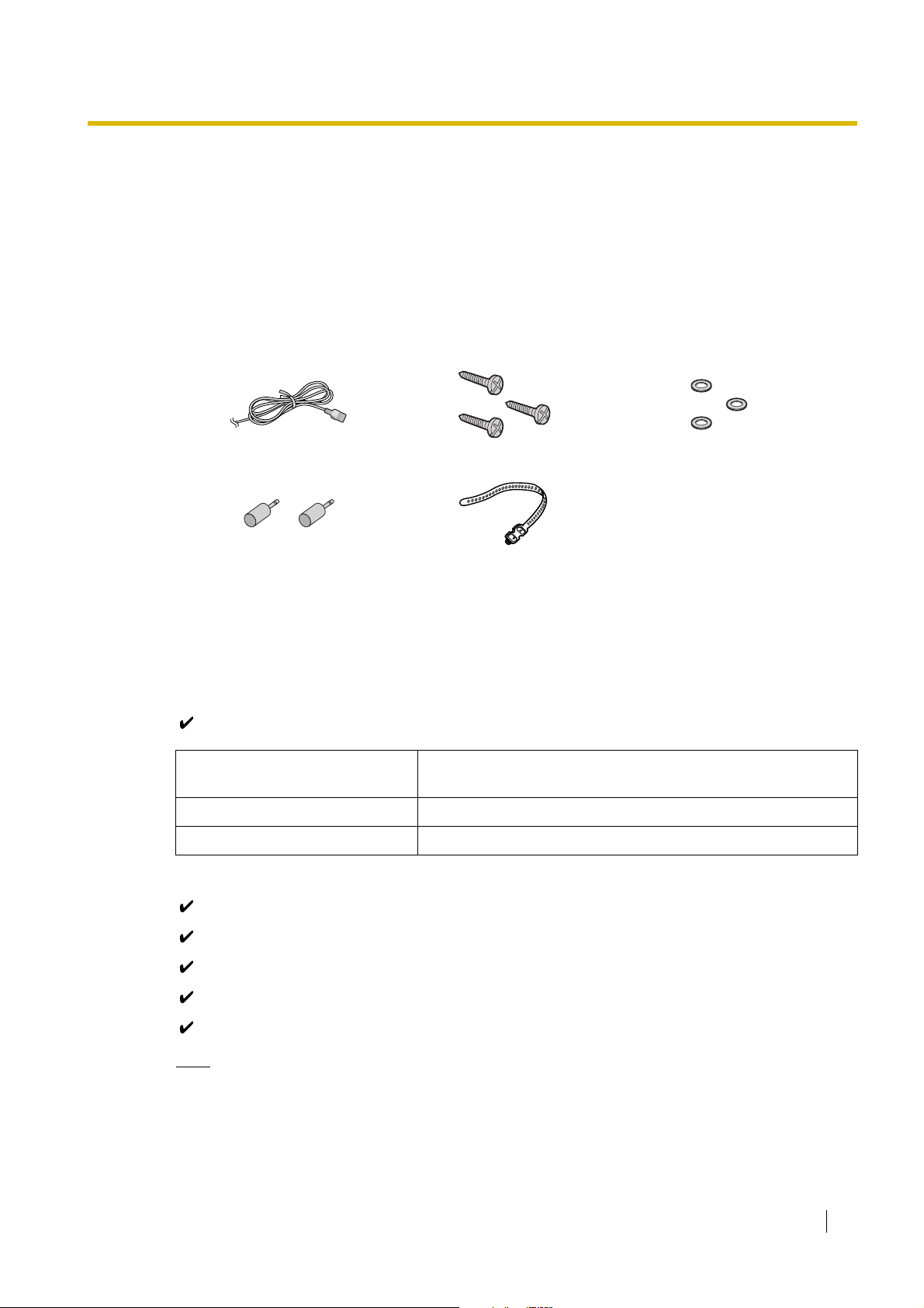
1.1 Unpacking
Check the package contents.
Main Unit × 1
CD-ROM (including manuals, etc.) × 1
Necessary tools (not supplied):
Telephone cable for extension connection:
The maximum length of the cable may vary depending on the type of the cables.
2-conductor connectors for outside (CO) line connections
4-conductor connectors for extension connections
Hammer × 1
KX-T7730 or KX-T7735 × 1
Screwdriver × 1
Note
Use a twisted pair cable for 2- or 4-conductor connector.
*AC Cord × 1 Screw × 3 Washer × 3
Mini Plug (for pager and music
source) × 2
Strap × 1
* The type of the AC cord may vary depending on the country/area of use.
More than one type of AC cord may be included for countries/areas in Central and South America.
Diameter of cable
(ø 0.4 mm to ø 0.6 mm)
Maximum length of cable
ø 0.5 mm 1128 m for SLT
ø 0.5 mm 229 m for PT and DSS Console
10 Getting Started
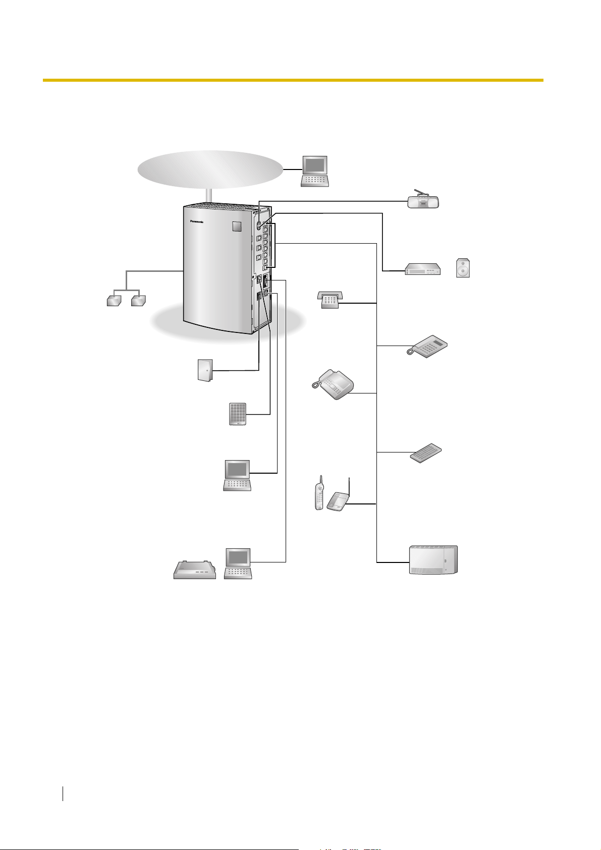
1.2 System Connection Diagram
• Connect a display-equipped proprietary telephone (PT) to extension jack 01, as this extension is
automatically designated as the manager extension.
• For supported extension types, refer to "2.3 Connecting Extensions".
Batteries
Voice Processing
System
Remote PC
SLT
Fax/Telephone
Answering Machine
PT
DSS Console
Wireless Phone
Outside (CO) Line
PC
Printer
External audio source
(radio, CD player, etc.)
Door Opener/
Doorbell/Door Chime
Doorphone
PC
Paging system
(loudspeaker, amplifier
and speaker, etc.)
Getting Started 11
2 Installation
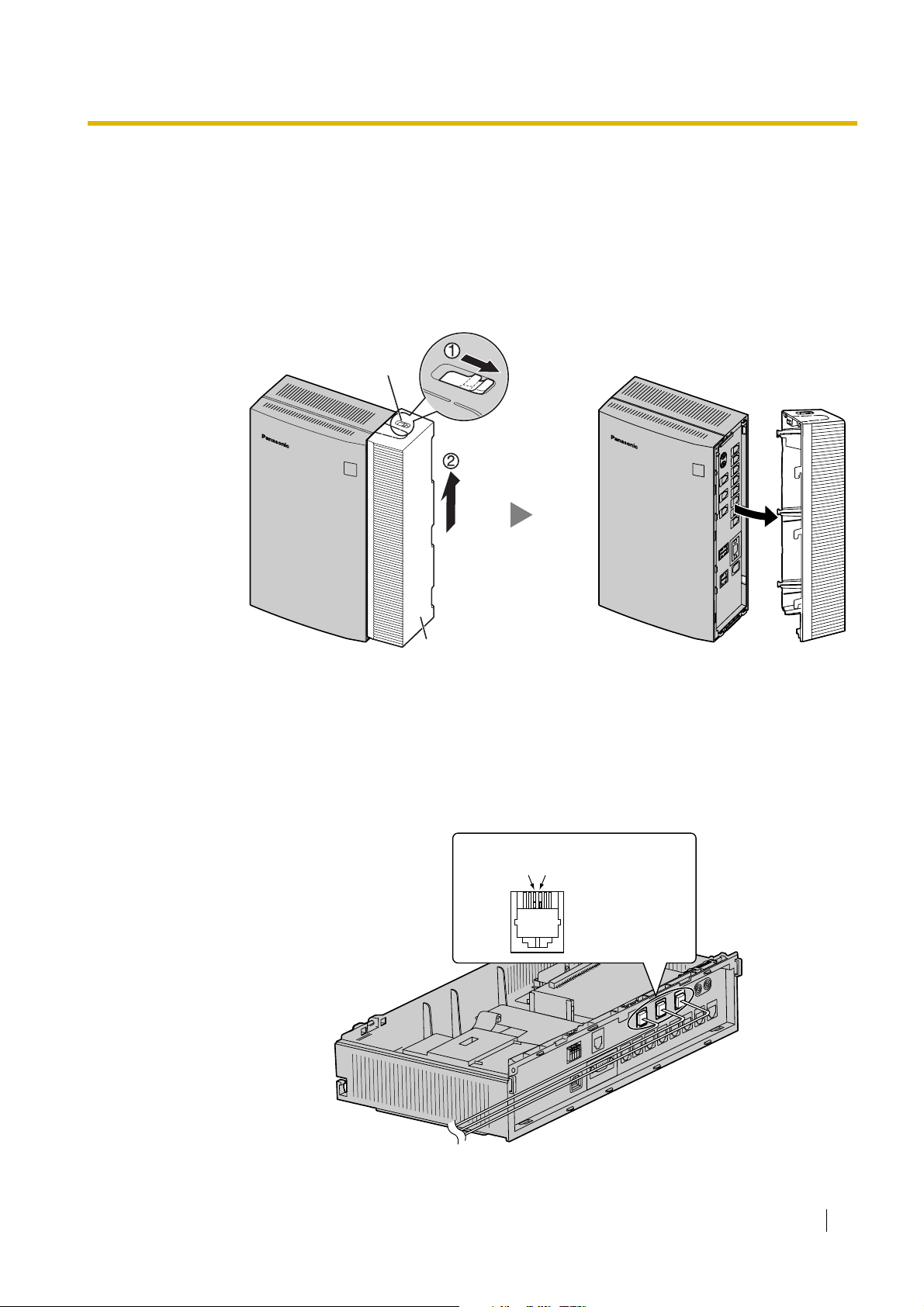
2.1 Opening Covers
1. Pull the slide button to the right and, holding it, slide the cable cover upwards. Then turn the cable
cover slightly to remove it.
2.2 Connecting Outside (CO) Lines
1. Insert the modular plugs of the telephone line cords (2-conductor wiring) into the outside (CO)
line jacks.
2. Connect the line cords to the terminal board or the modular jacks from the telephone company.
Slide Button
Cable Cover
To Terminal Board or Modular Jacks
from the Telephone Company
TR
T: Tip
R: Ring
TEL Jack for Outside(CO)Line
Loading...